LDK1020581500 Series Outdoor Mesh Access Point
Cisco Systems Inc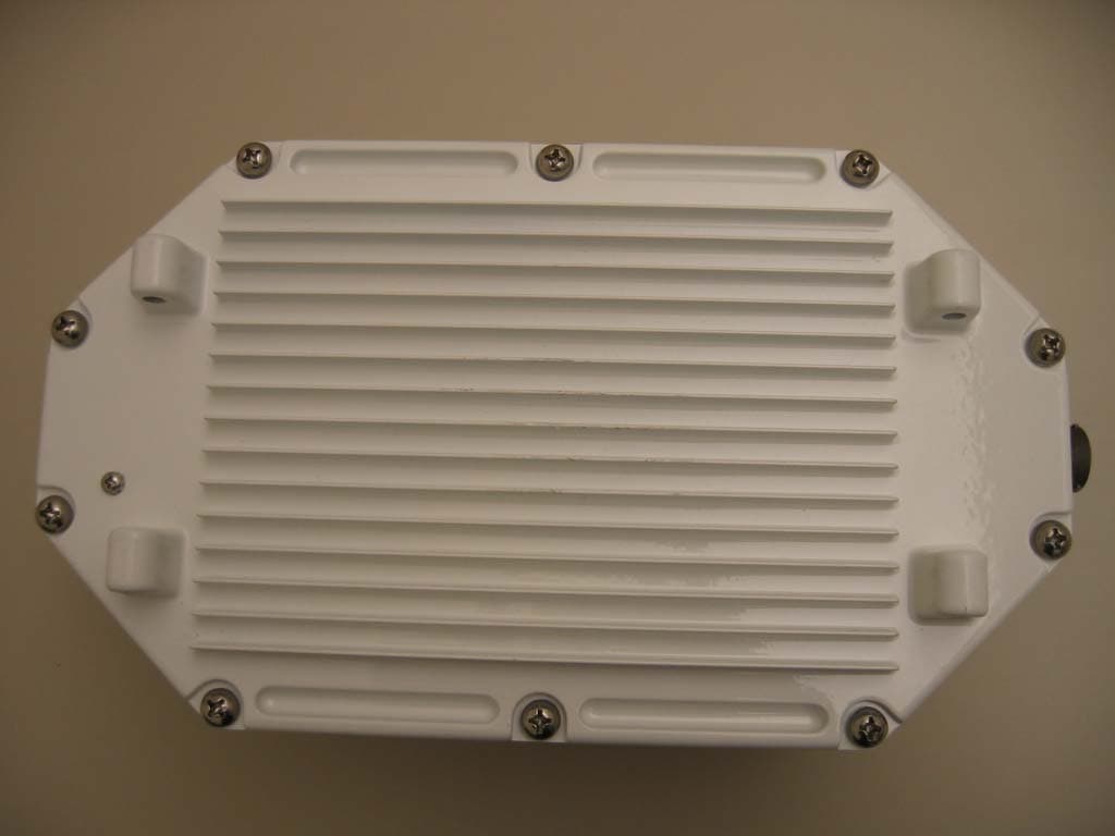
Click to zoom
Application Details
- Equipment Class
- DTS - Digital Transmission System
- Date of Grant
- Oct 23, 2005
- Application Purpose
- Original Equipment
- Date of Application
- Oct 23, 2005
- Equipment Note
- 1500 Series Outdoor Mesh Access Point
- Frequency Range
- 5745.00000000 - 5805.00000000
- Company
- Cisco Systems Inc
- Country
- United States
Documents & Files
Document Text
Text extracted from the exhibit documents filed with the FCC. Open a document above to read the original.
Users Manual
Corporate Headquarters Cisco Systems, Inc. 170 West Tasman Drive San Jose, CA 95134-1706 USA http://www.cisco.com Tel: 408 526-4000 800 553-NETS (6387) Fax: 408 526-4100 PRELIMINARY Quick Start Guide: Cisco Aironet 1500 Series Lightweight Outdoor Mesh Access Point August 25, 2005 Text Part Number: 78-17229-01 THE SPECIFICATIONS AND INFORMATION REGARDING THE PRODUCTS IN THIS MANUAL ARE SUBJECT TO CHANGE WITHOUT NOTICE. ALL STATEMENTS, INFORMATION, AND RECOMMENDATIONS IN THIS MANUAL ARE BELIEVED TO BE ACCURATE BUT ARE PRESENTED WITHOUT WARRANTY OF ANY KIND, EXPRESS OR IMPLIED. USERS MUST TAKE FULL RESPONSIBILITY FOR THEIR APPLICATION OF ANY PRODUCTS. THE SOFTWARE LICENSE AND LIMITED WARRANTY FOR THE ACCOMPANYING PRODUCT ARE SET FORTH IN THE INFORMATION PACKET THAT SHIPPED WITH THE PRODUCT AND ARE INCORPORATED HEREIN BY THIS REFERENCE. IF YOU ARE UNABLE TO LOCATE THE SOFTWARE LICENSE OR LIMITED WARRANTY, CONTACT YOUR CISCO REPRESENTATIVE FOR A COPY. The following information is for FCC compliance of Class A devices: This equipment has been tested and found to comply with the limits for a Class A digital device, pursuant to part 15 of the FCC rules. These limits are designed to provide reasonable protection against harmful interference when the equipment is operated in a commercial environment. This equipment generates, uses, and can radiate radio-frequency energy and, if not installed and used in accordance with the instruction manual, may cause harmful interference to radio communications. Operation of this equipment in a residential area is likely to cause harmful interference, in which case users will be required to correct the interference at their own expense. The following information is for FCC compliance of Class B devices: The equipment described in this manual generates and may radiate radio-frequency energy. If it is not installed in accordance with Cisco’s installation instructions, it may cause interference with radio and television reception. This equipment has been tested and found to comply with the limits for a Class B digital device in accordance with the specifications in part 15 of the FCC rules. These specifications are designed to provide reasonable protection against such interference in a residential installation. However, there is no guarantee that interference will not occur in a particular installation. Modifying the equipment without Cisco’s written authorization may result in the equipment no longer complying with FCC requirements for Class A or Class B digital devices. In that event, your right to use the equipment may be limited by FCC regulations, and you may be required to correct any interference to radio or television communications at your own expense. You can determine whether your equipment is causing interference by turning it off. If the interference stops, it was probably caused by the Cisco equipment or one of its peripheral devices. If the equipment causes interference to radio or television reception, try to correct the interference by using one or more of the following measures: • Turn the television or radio antenna until the interference stops. • Move the equipment to one side or the other of the television or radio. • Move the equipment farther away from the television or radio. • Plug the equipment into an outlet that is on a different circuit from the television or radio. (That is, make certain the equipment and the television or radio are on circuits controlled by different circuit breakers or fuses.) Modifications to this product not authorized by Cisco Systems, Inc. could void the FCC approval and negate your authority to operate the product. The Cisco implementation of TCP header compression is an adaptation of a program developed by the University of California, Berkeley (UCB) as part of UCB’s public domain version of the UNIX operating system. All rights reserved. Copyright © 1981, Regents of the University of California. NOTWITHSTANDING ANY OTHER WARRANTY HEREIN, ALL DOCUMENT FILES AND SOFTWARE OF THESE SUPPLIERS ARE PROVIDED “AS IS” WITH ALL FAULTS. CISCO AND THE ABOVE-NAMED SUPPLIERS DISCLAIM ALL WARRANTIES, EXPRESSED OR IMPLIED, INCLUDING, WITHOUT LIMITATION, THOSE OF MERCHANTABILITY, FITNESS FOR A PARTICULAR PURPOSE AND NONINFRINGEMENT OR ARISING FROM A COURSE OF DEALING, USAGE, OR TRADE PRACTICE. IN NO EVENT SHALL CISCO OR ITS SUPPLIERS BE LIABLE FOR ANY INDIRECT, SPECIAL, CONSEQUENTIAL, OR INCIDENTAL DAMAGES, INCLUDING, WITHOUT LIMITATION, LOST PROFITS OR LOSS OR DAMAGE TO DATA ARISING OUT OF THE USE OR INABILITY TO USE THIS MANUAL, EVEN IF CISCO OR ITS SUPPLIERS HAVE BEEN ADVISED OF THE POSSIBILITY OF SUCH DAMAGES. Quick Start Guide: Cisco Aironet 1500 Series Lightweight Outdoor Mesh Access Point ©2005 Cisco Systems, Inc. All rights reserved. CCIP, CCSP, the Cisco Arrow logo, the Cisco Powered Network mark, Cisco Unity, Follow Me Browsing, FormShare, and StackWise are trademarks of Cisco Systems, Inc.; Changing the Way We Work, Live, Play, and Learn, and iQuick Study are service marks of Cisco Systems, Inc.; and Aironet, ASIST, BPX, Catalyst, CCDA, CCDP, CCIE, CCNA, C CNP, Cisco, the Cisco Certified Internetwork Expert logo, Cisco IOS, the Cisco IOS logo, Cisco Press, Cisco Systems, Cisco Systems Capital, the Cisco Systems logo, Empowering the Internet Generation, Enterprise/Solver, EtherChannel, EtherSwitch, Fast Step, GigaStack, Internet Quotient, IOS, IP/TV, iQ Expertise, the iQ logo, iQ Net Readiness Scorecard, LightStream, MGX, MICA, the Networkers logo, Networking Academy, Network Registrar, Pa cke t, PIX, Post-Routing, Pre-Routing, RateMUX, Registrar, S criptShare, SlideCast, SMARTnet, StrataView Plus, Stratm, SwitchProbe, TeleRouter, The Fastest Way to Increase Your Internet Quotient, TransPath, and VCO are registered trademarks of Cisco Systems, Inc. and/or its affiliates in the United States and certain other countries. All other trademarks mentioned in this document or Website are the property of their respective own…
Text truncated - open the document above for the full version.
Cover Letter(s)
Jim Nicholson EMC Compliance Engineer Cisco Systems, Inc. 4125 Highlander Parkway Richfield, OH 44286 Phone: (330) 523-2094 Fax: (330) 523-2002 E-Mail: [email protected] July 18, 2005 Compliance Certification Services Certification Division 561F Monterey Road Morgan Hill, CA 95037 To whom it may concern: We, the undersigned, hereby authorize the Testing Division of Compliance Engineering Services, Inc., d.b.a. Compliance Certification Services and hereafter referred to as CCS, to act on our behalf in all manners relating to application for equipment authorization, including signing of all documents relating to these matters. Any and all acts carried out by CCS on our behalf shall have the same effect as acts of our own. We, the undersigned, hereby certify that we are not subject to a denial of federal benefits, that includes FCC benefits, pursuant to Section 5301 of the Anti-Drug Abuse Act of 1988, 21 U.S.C. 853(a). In authorizing CCS Testing Division as our agent, we still recognize that we are responsible to: a) comply with the relevant provisions of the certification program; b) make all necessary arrangements for the conduct of the evaluation, including provision for examining documentation and access to all areas, records (including internal audit reports) and personnel for the purposes of evaluation (e.g. testing, inspection, assessment, surveillance, reassessment) and resolution of complaints; c) make claims regarding certification only in respect of the scope for which certification has been granted; d) do not use our product certification in such a manner as to bring the Certification Division into disrepute and not make any statement regarding our product certification which the Certification Division may consider misleading or unauthorized; Jim Nicholson EMC Compliance Engineer Cisco Systems, Inc. 4125 Highlander Parkway Richfield, OH 44286 Phone: (330) 523-2094 Fax: (330) 523-2002 E-Mail: [email protected] e) upon suspension or cancellation of certification, discontinue use of all advertising matter that contains any reference thereto and return any certification documents as required by the Certification Division; f) use certification only to indicate the products are certified as being in conformity with specified standards; g) endeavor to ensure that no certificate or report nor any part thereof is used in a misleading manner; h) ensure that any reference to our product certification in communication media such as documents, brochures or advertising, complies with the requirements of the Certification Division; i) keep a record of all complaints made known to the us relating to the product’s compliance with requirements of the relevant standard and to make these records available to the Certification Division when requested; j) take appropriate action with respect to such complaints and any deficiencies found in products or services that affect compliance with the requirements for certification; k) document the actions taken. This authorization is valid until further written notice from the applicant. Best Regards, Jim Nicholson EMC Compliance Engineer
Cover Letter(s)
Cisco Systems, Inc. 4125 Highlander Parkway Richfield, Ohio 44286 Phone: 330 523-2094 Fax: 330 523-2002 http://www.cisco.com Phone: (330) 523-2094 Fax: (330) 523-2002 E-Mail: [email protected] August 29, 2005 Federal Communications Commission 7435 Oakland Mills Road Columbia MD 21046 Subject: Request for Confidentiality FCC ID: LDK102058 To Whom It May Concern: Pursuant to the provisions of Sections 0.457 and 0.459 of the Commission’s rules (47 CFR §§ 0.457, 0.459), we are requesting the Commission to withhold the following attachments as confidential documents from public disclosure indefinitely. Schematic Diagram Block Diagram Theory of Operation/Hardware Functional Specification Tune-up Procedure The above mentioned documents contain detailed system and equipment descriptions that are considered as proprietary information. Public disclosure of the above documents might be harmful to our company and would give competitors an unfair advantage in the market. Best Regards, Jim Nicholson EMC Compliance Engineer
Cover Letter(s)
Chris Harvey From: EASTECH [[email protected]] Sent: Wednesday, September 21, 2005 6:54 PM To: Mike Kuo Cc: Chris Harvey -TCB Subject: RE: Part 90 Subpart Y questions Page 1 of 3Message 9/22/2005 Mike: Sorry for the delay in response. Here is a summary of our answers: Question #1: In section 90.210 Mask L, it refer to Authorized Bandwidth. Does authorized bandwidth equal to 99% Bandwidth based upon the measurement ? or is it based upon the channel bandwidth as indicated in section 90.1215 ? Answer 1: Authorized Bandwidth is the channel bandwidth listed in 90.1215. Question #2: In section 90.1215 power limit which is based upon the channel bandwidth ( 1,5,10,15 and 20 MHz), if the 26dB bandwidth or 99% bandwidth is grater than channel bandwidth, is this device complied with technical requirement? for example, carrier frequency is 4980 MHz, the measured 26dB or 99% bandwidth is 25 MHz. Does it comply ? Answer 2: No. The measured bandwidth may not exceed the authorized channel bandwidth. Question #3: Necessary bandwidth for emission designator purpose. Shall necessary bandwidth base upon channel bandwidth or based upon 99% Bandwidth measurement ? Answer 3: Necessary bandwidth is based upon 99% bandwidth measurement and is used for the emission designator Further you asked if the access point that you describe will be a composite device and does not need to be an SDR. This is based on your description and assumption that there are no configuration options for non-US operation. We are also assuming that these devices are not portable and based on our guidance in the past TCBs may review them. Please let us know if there are any other questions. Rashmi Doshi, PhD Chief, FCC Laboratories -----Original Message----- From: Mike Kuo [mailto:[email protected]] Sent: Wednesday, September 14, 2005 3:27 PM To: EASTECH Cc: Chris Harvey -TCB Subject: Part 90 Subpart Y questions § 90.209 Bandwidth limitations. (a) Each authorization issued to a station licensed under this part will show an emission designator representing the class of emission authorized. The designator will be prefixed by a specified necessary bandwidth. This number does not necessarily indicate the bandwidth occupied by the emission at any instant. In those cases where §2.202 of this chapter does not provide a formula for the computation of necessary bandwidth, the occupied bandwidth, as defined in part 2 of this chapter, may be used in lieu of the necessary bandwidth. § 2.202 Bandwidths. (a) Occupied bandwidth. The frequency bandwidth such that, below its lower and above its upper frequency limits, the mean powers radiated are each equal to 0.5 percent of the total mean power radiated by a given emission. In some cases, for example multichannel frequency-division systems, the percentage of 0.5 percent may lead to certain difficulties in the practical application of the definitions of occupied and necessary bandwidth; in such cases a different percentage may prove useful. § 90.7 Definitions. Authorized bandwidth. The frequency band, specified in kilohertz and centered on the carrier frequency containing those frequencies upon which a total of 99 percent of the radiated power appears, extended to include any discrete frequency upon which the power is at least 0.25 percent of the total radiated power. FCC Part 90 Subpart Y Section 90.210 Emission Mask Emission Mask L: (l) Emission Mask L. For low power transmitters (20 dBm or less) operating in the 4940–4990 MHz frequency band, the power spectral density of the emissions must be attenuated below the output power of the transmitter as follows: (1) On any frequency removed from the assigned frequency between 0–45% of the authorized bandwidth (BW): 0 dB. (2) On any frequency removed from the assigned frequency between 45–50% of the authorized bandwidth: 219 log (% of (BW)/45) dB. (3) On any frequency removed from the assigned frequency between 50–55% of the authorized bandwidth: 10 + 242 log (% of (BW)/50) dB. (4) On any frequency removed from the assigned frequency between 55–100% of the authorized bandwidth: 20 + 31 log (% of (BW)/55) dB attenuation. (5) On any frequency removed from the assigned frequency between 100–150% of the authorized bandwidth: 28 + 68 log (% of (BW)/100) dB attenuation. (6) On any frequency removed from the assigned frequency above 150% of the authorized bandwidth: 50 dB. (7) The zero dB reference is measured relative to the highest average power of the fundamental emission measured across the designated channel bandwidth using a resolution bandwidth of at least one percent of the occupied bandwidth of the fundamental emission and a video bandwidth of 30 kHz. The power spectral density is the power measured within the resolution bandwidth of the measurement device divided by the resolution bandwidth of the measurement device. Emission levels are also based on the use of measurement instrumentation employing a resolution bandwidth of at least one percent of the occupied bandwidth. With above definition in mind, I would like to post the following questions which are related to Part 90 Subpart Y. Question #1: In section 90.210 Mask L, it refer to Authorized Bandwidth. Does authorized bandwidth equal to 99% Bandwidth based upon the measurement ? or is it based upon the channel bandwidth as indicated in section Page 2 of 3Message 9/22/2005 90.1215 ? Question #2: In section 90.1215 power limit which is based upon the channel bandwidth ( 1,5,10,15 and 20 MHz), if the 26dB bandwidth or 99% bandwidth is grater than channel bandwidth, is this device complied with technical requirement? for example, carrier frequency is 4980 MHz, the measured 26dB or 99% bandwidth is 25 MHz. Does it comply ? Question #3: Necessary bandwidth for emission designator purpose. Shall necessary bandwidth base upon channel bandwidth or based upon 99% Bandwidth measurement ? Currently, we have received two applications which are very similar to each other. Both EUT( Access Point ) are equipped with A…
Text truncated - open the document above for the full version.
Cover Letter(s)
Chris Harvey From: Jim Nicholson (jimnicho) [[email protected]] Sent: Tuesday, September 27, 2005 5:57 PM To: Compliance Certification Services Cc: Mike Kuo; Barbara Judge; Michael Heckrotte Subject: RE: Cisco Systems, Inc., FCC ID: LDK102058, Assessment NO.: AN05T5119, Notice#1 Page 1 of 2 9/28/2005 See my responses below. Jim -----Original Message----- From: Compliance Certification Services [mailto:[email protected]] Sent: Friday, September 23, 2005 11:17 AM To: Jim Nicholson [[email protected]] Cc: [email protected] Subject: Cisco Systems, Inc., FCC ID: LDK102058, Assessment NO.: AN05T5119, Notice#1 Jim, I have begun the review of the above referenced Pt. 15 and Pt. 90 applications and have found that the following items need to be addressed before the application review can be completed. 1. The test reports do not indicate that testing was performed in accordance with ANSIC63.4:2003 nor do they adequately document the test procedures used for the compliance measurements. Please submit the test procedures used for compliance tests that are referenced in Appendix C. In the future please include these test procedures in the test report documentation. It can not be determined from the information provided if the EUT complies with many of the FCC requirements (i.e. Peak Power Output using RBW > emission bandwidth).[JN] The test procedures pertinent to this report are attached. If at all possible, can we avoid posting these on the FCC site? 2. Please ensure that plots in the test report have the measurement parameters (RBW, VBW, sweep time, detector mode, etc.) included as part of the plot (i.e. the Conducted Spurious emissions plots). [JN] The requested parameters are included in the test procedures attached. 3. The Conducted Spurious Emissions limit of -30dBc has been used in this report, which implies (per FCC 15.247(d)) that the Peak Transmit Power was measured with an RMS Average Detector. Please clarify this in the test report.[JN] The Peak Transmit Power was measured as indicated in the attached test procedure. 4. MPE is calculated with separate operation and the Operational Description indicates that the unit apparently operates simultaneous with 802.11b/g (2.4GHz) and 802.11a (5.7GHz). The MPE exhibit needs to be recalculated for simultaneous transmission in accordance with OET 65.[JN] I’ve attached an updated test report which includes this calculation for 2.4/5GHz and 2.4/4.9GHz collocation. note: This approval request is for a composite FCC 15.247 and FCC Pt. 90 Subpart Y device, submitted under 2 applications. Questions pertaining to the FCC 90-Y portion of this application are under separate cover. best regards, Chris Harvey [email protected] The items indicated above must be submitted before processing can continue on the above referenced application. Failure to provide the requested information within 30 days of the original e-mail date may result in application dismissal and forfeiture of the filing fee. Also, please note that partial responses increase processing time and should not be submitted. Any questions about the content of this correspondence should be directed to the e-mail address listed below the name of the sender. Page 2 of 2 9/28/2005
ID Label/Location Info
PROPOSED FCC ID LABEL AND LOCATION CISCO SYSTEMS, INC. This device complies with Part 15 of the FCC Rules. Operation is subject to the following two conditions: (1) this device may not cause harmful interference, and (2) this device must accept any interference received, including interference that may cause undesired operation. FCC ID: LDK102058 FCC ID LABEL LOCATION
Parts List/Tune Up Info
Cisco Systems, Inc. All contents are Copyright © 2003 Cisco Systems, Inc. All rights reserved. Important Notices and Privacy Statement. Page 1 of 4 Data Sheet CiscoAironet 5 GHz Bridge Antennas and Accessories—Complete the Wireless Solution Cisco offers a complete range of antennas for 5 GHz bridging applications that enable a customized wireless solution for almost any installation. Cisco Aironet Bridge Antennas and Accessories Every wireless bridge deployment is different. When engineering a building-to-building solution, varying distances, configurations, and installation requirements create the need for a flexible solution. Cisco ® is committed to providing not only the best wireless bridges in the industry—it is also committed to providing a complete solution for any wireless bridge deployment. Figure 1 With Cisco Aironet Bridge Antennas, the Right Mounting Hardware, and Qualified Installation, Wireless Links Over Great Distances and Obstacles are Possible With the Cisco FCC-approved directional 1 and omni-directional 2 antennas, mounting hardware, and other accessories, installers can customize a wireless solution that meets the requirements of even the most challenging applications (Figure 1). Cisco Aironet ® bridges can be ordered with standard antennas that provide sufficient range 3 for many applications. To extend the transmission range for more specialized applications, a variety of optional, higher-gain 4 antennas are provided that are compatible with the bridge (Table 1). 1. An antenna that concentrates transmission power into a direction that increases coverage distance at the expense of coverage angle. Directional antenna types include patch and parabolic dish antennas. A patch antenna is a type of flat antenna that radiates a hemispherical coverage area. A parabolic dish antenna is a concave or dish-shaped object, often referred to as a dish antenna. Parabolic dish antennas tend to provide the greatest gain and the narrowest beam width making them ideal for point-to-point transmission over the longest distances. 2. An antenna that provides a 360-degree transmission pattern. These types of antennas are used when coverage in all directions is required. 3. A linear measure of the distance between a transmitter and receiver. 4. An antenna that concentrates its signal energy by reducing the angle of coverage. Antenna gain does not amplify the transmitted power of a radio, but simply focuses energy in a given direction. Therefore, as antenna gain increases, the angle of coverage decreases. Cisco Systems, Inc. All contents are Copyright © 2003 Cisco Systems, Inc. All rights reserved. Important Notices and Privacy Statement. Page 2 of 4 Bridge Antennas Cisco Aironet bridge antennas allow for extraordinary transmission distances between two or more buildings. Available in directional configurations for point-to-point transmission and sector or omni-directional configurations for point-to-multipoint implementations, Cisco has a bridge antenna for every application (Table 1). The antennas are available with different gain and range capabilities, beam widths, 5 and form factors. Table 1Cisco Aironet Bridge Antenna Features FeatureAIR-ANT58G9VOA-NAIR-ANT58G10SSA-NAIR-ANT58G28SDA-N Description• Omni-directional • Mast mount • Sector antenna • Mast mount • Dish antenna • Mast mount Application• Outdoor short-range point-to-multipoint applications • Outdoor medium-range point-to-point and point-to-multipoint applications • Outdoor long-range directional connections Gain (including supplied jumper cable)• 9.0 dBi• 9.5 dBi• 28.0 dBi Polarization• Vertical• Vertical or horizontal • Field configurable • Vertical or horizontal • Field configurable Elevation adjustment• None• None• +/- 12.5 degrees Approximate range at 9 Mbps 6 • 8 miles (13 km) (with 22.5 dBi captive antenna on the remote site) • 8 miles (13 km) (with 22.5 dBi captive antenna on the remote site) • 23 miles (37 km) (with 28 dBi antennas on each end) Approximate range at 54 Mbps 6 • 2 miles (3 km) (with 22.5 dBi captive antenna on the remote site) • 2 miles (3 km) (with 22.5 dBi captive antenna on the remote site) • 12 miles (19 km) (with 28 dBi antennas on each end) Beam width• 360 H, 6 V• 60 H, 60 V• 5.7 H, 6 V Supplied jumper cable length• 4.9 ft. (1.5 m)• 4.9 ft. (1.5 m)• 4.9 ft. (1.5 m) Dimensions• Length: 18 in. (46 cm) • Diameter: 1 in. (2.5 cm) • Length: 2.5 in. (6.4 cm) • Width: 2.5 in. (6.4 cm) • Depth: 1.75 in. (4.5 cm) • Diameter: 29 in. (74 cm) • Depth: 14.5 in. (36.8 cm) Weight• 2.0 lb. (0.9 kg)• 1.25 lb. (0.6 kg)• 9.5 lb. (4.3 kg) 5. The angle of signal coverage provided by an antenna; it may be decreased by a directional antenna to increase gain. 6. The distances referenced here are approximations and should be used for estimation purposes only. Cisco Systems, Inc. All contents are Copyright © 2003 Cisco Systems, Inc. All rights reserved. Important Notices and Privacy Statement. Page 3 of 4 Power Injector Cables Typical installations will place the outdoor unit on an external mast with the power injector unit placed indoors. These cables come with a pair of F-type connectors on each end. To allow flexibility in the distance between the units, a variety of cables are available (Figure 2 and Table 2). Figure 2 Cisco Aironet Power Injector Cables Accessories To complete an installation, Cisco provides a variety of accessories that offer increased functionality, safety, and convenience (Figure 3 and Table 3). Figure 3 Cisco Aironet Bridge Accessories Table 2Cisco Aironet Power Injector Cable Features FeatureAIR-CAB020DRG6-F=AIR-CAB050DRG6-F=AIR-CAB100DRG6-F Cable length20 ft. (6m)50 ft. (15m)100 ft. (30m) Corporate Headquarters Cisco Systems, Inc. 170 West Tasman Drive San Jose, CA 95134-1706 USA www.cisco.com Tel: 408 526-4000 800 553-NETS (6387) Fax: 408 526-4100 European Headquarters Cisco Systems International BV Haarlerbergpark Haarlerbergweg 13-19 1101 CH Amsterdam The Netherlands www-europe.cisco.com Tel: 31…
Text truncated - open the document above for the full version.
Parts List/Tune Up Info
Measured Antenna Patterns for AIR-ANT2455V-N 2.4 GHz Direct Mount Omni Basic Specs (1) 2:1 VSWR Bandwidth: 2400 MHz – 2500 MHz (2) Peak Gain = 5.5 dBi (3) Azimuth Plane 3-dB Beamwidth = Omnidirectional (4) Elevation Plane 3-dB Beamwidth = 25 degrees (5) Azimuth Plane Ripple = < 1 dB (6) First Sidelobe Level = -8 dBc 45 90 135 180 225 270 315 -35 -30 -25 -20 -15 -10 -5 0 45 90 135 180 225 270 315 -35 -30 -25 -20 -15 -10 -5 0
Parts List/Tune Up Info
Measured Antenna Patterns for AIR-ANT5175V-N 5 GHz Direct Mount Omni Basic Specs (1) 2:1 VSWR Bandwidth: 4900 MHz – 5850 MHz (2) Peak Gain, 4.9 GHz band = 6.5 dBi (3) Peak Gain, 5.4 GHz – 5.85 GHz = 7.5 dBi (4) Azimuth Plane 3-dB Beamwidth = Omnidirectional (5) Elevation Plane 3-dB Beamwidth = 16 degrees (6) Azimuth Plane Ripple = 1.5 dB (7) First Sidelobe Level = -10 dBc 45 90 135 180 225 270 315 -35 -30 -25 -20 -15 -10 -5 0 45 90 135 180 225 270 315 -35 -30 -25 -20 -15 -10 -5 0
Parts List/Tune Up Info
Measured Antenna Patterns for Cushcraft S2406BP 2.4 GHz 8 dBi Omni Basic Specs (1) 2:1 VSWR Bandwidth: 2400 MHz – 2500 MHz (2) Peak Gain = 8 dBi (3) Azimuth Plane 3-dB Beamwidth = Omnidirectional (4) Elevation Plane 3-dB Beamwidth = 12 degrees (5) Azimuth Plane Ripple = 1 dB (6) First Sidelobe Level = -10 dBc 0 350 340 330 320 310 300 290 280 270 260 250 240 230 220 210 200 190 180 170 160 150 140 130 120 110 100 90 80 70 60 50 40 30 20 10 -30-20-100 dB H Plane 2. 45 GHz 0 350 340 330 320 310 300 290 280 270 260 250 240 230 220 210 200 190 180 170 160 150 140 130 120 110 100 90 80 70 60 50 40 30 20 10 -30-20-100 dB E Plane 2. 45 GHz
Parts List/Tune Up Info
Measured Antenna Patterns for Cushcraft S49014WP 5 GHz 14 dBi Patch Basic Specs (1) 2:1 VSWR Bandwidth: 4900 MHz – 5850 MHz (2) Peak Gain = 14 dBi (3) Azimuth Plane 3-dB Beamwidth = 30 degrees (4) Elevation Plane 3-dB Beamwidth = 26 degrees (5) First Sidelobe Level = -10 dBc (6) F/B Ratio > 20 dB Azim uth Plane Pattern Cushcraft S49014WP 14 dBi Panel 45 90 135 180 225 270 315 -35 -30 -25 -20 -15 -10 -5 0 Elevation Plane Pattern Cushcraft S49014WP 14 dBi Panel 45 90 135 180 225 270 315 -35 -30 -25 -20 -15 -10 -5 0
Parts List/Tune Up Info
Measured Antenna Patterns for Cushcraft S54717P 5 GHz 17 dBi Patch Basic Specs (1) 2:1 VSWR Bandwidth: 5400 MHz – 5850 MHz (2) Peak Gain = 17 dBi (3) Azimuth Plane 3-dB Beamwidth = 17 degrees (4) Elevation Plane 3-dB Beamwidth = 17 degrees (5) First Sidelobe Level = -10 dBc (6) F/B Ratio > 25 dB Azim uth Plane Pattern Cushcraft S54717P 17 dBi Panel 45 90 135 180 225 270 315 -35 -30 -25 -20 -15 -10 -5 0 Elevation Plane Pattern Cushcraft S54717P 17 dBi Panel 45 90 135 180 225 270 315 -35 -30 -25 -20 -15 -10 -5 0
Parts List/Tune Up Info
Measured Antenna Patterns for Maxrad MP49020 5 GHz 20 dBi Patch Basic Specs (1) 2:1 VSWR Bandwidth: 4900 MHz – 5850 MHz (2) Peak Gain = 20 dBi (3) Azimuth Plane 3-dB Beamwidth = 10 degrees (4) Elevation Plane 3-dB Beamwidth = 10 degrees (5) First Sidelobe Level = -12 dBc (6) F/B Ratio > 30 dB Azim uth Plane Pattern Maxrad MP49020 20 dBi Panel 45 90 135 180 225 270 315 -35 -30 -25 -20 -15 -10 -5 0 Elevation Plane Pattern Maxrad MP49020 20 dBi Panel 45 90 135 180 225 270 315 -35 -30 -25 -20 -15 -10 -5 0
Test Report
EMC Test Report No: EDCS - 467105 FCC ID: LDK102058, Canada: 2461B-102058 Page No: 1 of 77 This document is uncontrolled. Please refer to the electronic copy within EDCS for the most up to date version. Cisco Systems, Inc. Company Confidential Test Report: EDCS - 467105 For AIR-LAP1510AG-A-K9 (United States) and AIR-LAP1510AG-N-K9 (Canada, Australia, New Zealand, Mexico, and Taiwan) Cisco Aironet 1500 Series Outdoor Mesh Access Points Against the following Specifications : CFR47 Parts 15.247, RSS-210, LP0002, AS/NZS 4268:2003 Cisco Systems EMC Laboratory 170 West Tasman Drive San Jose, CA 95134 Certificate Number : 1178-01 Author: James Nicholson Approved By: Title: EMC Test Report No: EDCS - 467105 FCC ID: LDK102058, Canada: 2461B-102058 Page No: 2 of 77 This document is uncontrolled. Please refer to the electronic copy within EDCS for the most up to date version. Cisco Systems, Inc. Company Confidential This test report has been electronically authorized and archived using the CISCO Engineering Document Control system. SECTION 1: OVERVIEW..............................................................................................…
Text truncated - open the document above for the full version.
Contact Information
Applicant
Samuel Kim(Manager, Engineering)
Test Firm
Cisco Systems, Inc.Daisy Poon
Technical Specifications
| # | Rule Parts | Frequency Range | Power Output |
|---|---|---|---|
| 2 | 15C | 5.75 GHz - 5.80 GHz | 545.00 mW |
Other Applications from Cisco Systems Inc

LDKJ98213058
May 25, 2026Wireless Phone
Equipment Class
DSS - Part 15 Spread Spectrum TransmitterLDKIW9165E
Aug 20, 2024Wi-Fi 6E Outdoor Access Point
Equipment Class
6SD - 15E 6 GHz Standard Power Access PointLDKIW9165DH
Aug 05, 2024Wi-Fi 6E Outdoor Access Point
Equipment Class
6SD - 15E 6 GHz Standard Power Access PointLDKUSBC2857
Jul 22, 2024Cisco Headset USB-C Adapter
Equipment Class
DSS - Part 15 Spread Spectrum TransmitterLDKESPRD2922
May 09, 2024UC Phone
Equipment Class
NII - Unlicensed National Information Infrastructure TX