LDK102060802.11g Radio Module
Cisco Systems Inc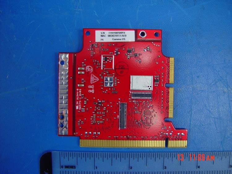
Click to zoom
Application Details
- Equipment Class
- DTS - Digital Transmission System
- Date of Grant
- Aug 06, 2006
- Application Purpose
- Original Equipment
- Date of Application
- Aug 06, 2006
- Equipment Note
- 802.11g Radio Module
- Frequency Range
- 2412.00000000 - 2462.00000000
- Company
- Cisco Systems Inc
- Country
- United States
Documents & Files
Document Text
Text extracted from the exhibit documents filed with the FCC. Open a document above to read the original.
Users Manual
CISCO CONFIDENTIAL - Draft 1 Corporate Headquarters Cisco Systems, Inc. 170 West Tasman Drive San Jose, CA 95134-1706 USA http://www.cisco.com Tel: 408 526-4000 800 553-NETS (6387) Fax: 408 526-4100 Cisco Aironet 1250AG Series Access Point Hardware Installation Guide June 2006 Text Part Number: OL-8247-01 CISCO CONFIDENTIAL - Draft 1 THE SPECIFICATIONS AND INFORMATION REGARDING THE PRODUCTS IN THIS MANUAL ARE SUBJECT TO CHANGE WITHOUT NOTICE. ALL STATEMENTS, INFORMATION, AND RECOMMENDATIONS IN THIS MANUAL ARE BELIEVED TO BE ACCURATE BUT ARE PRESENTED WITHOUT WARRANTY OF ANY KIND, EXPRESS OR IMPLIED. USERS MUST TAKE FULL RESPONSIBILITY FOR THEIR APPLICATION OF ANY PRODUCTS. THE SOFTWARE LICENSE AND LIMITED WARRANTY FOR THE ACCOMPANYING PRODUCT ARE SET FORTH IN THE INFORMATION PACKET THAT SHIPPED WITH THE PRODUCT AND ARE INCORPORATED HEREIN BY THIS REFERENCE. IF YOU ARE UNABLE TO LOCATE THE SOFTWARE LICENSE OR LIMITED WARRANTY, CONTACT YOUR CISCO REPRESENTATIVE FOR A COPY. The following information is for FCC compliance of Class A devices: This equipment has been tested and found to comply with the limits for a Class A digital device, pursuant to part 15 of the FCC rules. These limits are designed to provide reasonable protection against harmful interference when the equipment is operated in a commercial environment. This equipment generates, uses, and can radiate radio-frequency energy and, if not installed and used in accordance with the instruction manual, may cause harmful interference to radio communications. Operation of this equipment in a residential area is likely to cause harmful interference, in which case users will be required to correct the interference at their own expense. The following information is for FCC compliance of Class B devices: The equipment described in this manual generates and may radiate radio-frequency energy. If it is not installed in accordance with Cisco’s installation instructions, it may cause interference with radio and television reception. This equipment has been tested and found to comply with the limits for a Class B digital device in accordance with the specifications in part 15 of the FCC rules. These specifications are designed to provide reasonable protection against such interference in a residential installation. However, there is no guarantee that interference will not occur in a particular installation. Modifying the equipment without Cisco’s written authorization may result in the equipment no longer complying with FCC requirements for Class A or Class B digital devices. In that event, your right to use the equipment may be limited by FCC regulations, and you may be required to correct any interference to radio or television communications at your own expense. You can determine whether your equipment is causing interference by turning it off. If the interference stops, it was probably caused by the Cisco equipment or one of its peripheral devices. If the equipment causes interference to radio or television reception, try to correct the interference by using one or more of the following measures: • Turn the television or radio antenna until the interference stops. • Move the equipment to one side or the other of the television or radio. • Move the equipment farther away from the television or radio. • Plug the equipment into an outlet that is on a different circuit from the television or radio. (That is, make certain the equipment and the television or radio are on circuits controlled by different circuit breakers or fuses.) Modifications to this product not authorized by Cisco Systems, Inc. could void the FCC approval and negate your authority to operate the product. The Cisco implementation of TCP header compression is an adaptation of a program developed by the University of California, Berkeley (UCB) as part of UCB’s public domain version of the UNIX operating system. All rights reserved. Copyright © 1981, Regents of the University of California. NOTWITHSTANDING ANY OTHER WARRANTY HEREIN, ALL DOCUMENT FILES AND SOFTWARE OF THESE SUPPLIERS ARE PROVIDED “AS IS” WITH ALL FAULTS. CISCO AND THE ABOVE-NAMED SUPPLIERS DISCLAIM ALL WARRANTIES, EXPRESSED OR IMPLIED, INCLUDING, WITHOUT LIMITATION, THOSE OF MERCHANTABILITY, FITNESS FOR A PARTICULAR PURPOSE AND NONINFRINGEMENT OR ARISING FROM A COURSE OF DEALING, USAGE, OR TRADE PRACTICE. IN NO EVENT SHALL CISCO OR ITS SUPPLIERS BE LIABLE FOR ANY INDIRECT, SPECIAL, CONSEQUENTIAL, OR INCIDENTAL DAMAGES, INCLUDING, WITHOUT LIMITATION, LOST PROFITS OR LOSS OR DAMAGE TO DATA ARISING OUT OF THE USE OR INABILITY TO USE THIS MANUAL, EVEN IF CISCO OR ITS SUPPLIERS HAVE BEEN ADVISED OF THE POSSIBILITY OF SUCH DAMAGES. Cisco Aironet 1250AG Series Access Point Hardware Installation Guide © 2006 Cisco Systems, Inc. All rights reserved. CCSP, CCVP, the Cisco Square Bridge logo, Follow Me Browsing, and StackWise are trademarks of Cisco Systems, Inc.; Changing the Way We Work, Live, Play, and Learn, and iQuick Study are service marks of Cisco Systems, Inc.; and Access Registrar, Aironet, BPX, Catalyst, CCDA, CCDP, CCIE, CCIP, CCNA, CCNP, Cisco, the Cisco Certified Internetwork Expert logo, Cisco IOS, Cisco Press, Cisco Systems, Cisco Systems Capital, the Cisco Systems logo, Cisco Unity, Enterprise/Solver, EtherChannel, EtherFast, EtherSwitch, Fast Step, FormShare, GigaDrive, GigaStack, HomeLink, Internet Quotient, IOS, IP/TV, iQ Expertise, the iQ logo, iQ Net Readiness Scorecard, LightStream, Linksys, MeetingPlace, MGX, the Networkers logo, Networking Academy, Network Registrar, Packet, PIX, Post-Routing, Pre-Routing, ProConnect, RateMUX, ScriptShare, SlideCast, SMARTnet, The Fastest Way to Increase Your Internet Quotient, and TransPath are registered trademarks of Cisco Systems, Inc. and/or its affiliates in the United States and certain other countries. All other trademarks mentioned in this document or Website are the property of their respective owners. The use of the word partner does not imply a partnershi…
Text truncated - open the document above for the full version.
Cover Letter(s)
Jim Nicholson EMC Compliance Engineer Cisco Systems, Inc. 4125 Highlander Parkway Richfield, OH 44286 Phone: (330) 523-2094 Fax: (330) 523-2002 E-Mail: [email protected] July 18, 2005 Compliance Certification Services Certification Division 561F Monterey Road Morgan Hill, CA 95037 To whom it may concern: We, the undersigned, hereby authorize the Testing Division of Compliance Engineering Services, Inc., d.b.a. Compliance Certification Services and hereafter referred to as CCS, to act on our behalf in all manners relating to application for equipment authorization, including signing of all documents relating to these matters. Any and all acts carried out by CCS on our behalf shall have the same effect as acts of our own. We, the undersigned, hereby certify that we are not subject to a denial of federal benefits, that includes FCC benefits, pursuant to Section 5301 of the Anti-Drug Abuse Act of 1988, 21 U.S.C. 853(a). In authorizing CCS Testing Division as our agent, we still recognize that we are responsible to: a) comply with the relevant provisions of the certification program; b) make all necessary arrangements for the conduct of the evaluation, including provision for examining documentation and access to all areas, records (including internal audit reports) and personnel for the purposes of evaluation (e.g. testing, inspection, assessment, surveillance, reassessment) and resolution of complaints; c) make claims regarding certification only in respect of the scope for which certification has been granted; d) do not use our product certification in such a manner as to bring the Certification Division into disrepute and not make any statement regarding our product certification which the Certification Division may consider misleading or unauthorized; Jim Nicholson EMC Compliance Engineer Cisco Systems, Inc. 4125 Highlander Parkway Richfield, OH 44286 Phone: (330) 523-2094 Fax: (330) 523-2002 E-Mail: [email protected] e) upon suspension or cancellation of certification, discontinue use of all advertising matter that contains any reference thereto and return any certification documents as required by the Certification Division; f) use certification only to indicate the products are certified as being in conformity with specified standards; g) endeavor to ensure that no certificate or report nor any part thereof is used in a misleading manner; h) ensure that any reference to our product certification in communication media such as documents, brochures or advertising, complies with the requirements of the Certification Division; i) keep a record of all complaints made known to the us relating to the product’s compliance with requirements of the relevant standard and to make these records available to the Certification Division when requested; j) take appropriate action with respect to such complaints and any deficiencies found in products or services that affect compliance with the requirements for certification; k) document the actions taken. This authorization is valid until further written notice from the applicant. Best Regards, Jim Nicholson EMC Compliance Engineer
Cover Letter(s)
Cisco Systems, Inc. 4125 Highlander Parkway Richfield, Ohio 44286 Phone: 330 523-2094 Fax: 330 523-2002 http://www.cisco.com Phone: (330) 523-2094 Fax: (330) 523-2002 E-Mail: [email protected] April 11, 2006 Federal Communications Commission 7435 Oakland Mills Road Columbia MD 21046 Subject: Request for Confidentiality FCC ID: LDK102060 To Whom It May Concern: Pursuant to the provisions of Sections 0.457 and 0.459 of the Commission’s rules (47 CFR §§ 0.457, 0.459), we are requesting the Commission to withhold the following attachments as confidential documents from public disclosure indefinitely. Schematic Diagram Block Diagram Theory of Operation Best Regards, Jim Nicholson EMC Compliance Engineer
Cover Letter(s)
Jim Nicholson EMC Compliance Engineer Cisco Systems, Inc. 4125 Highlander Parkway Richfield, OH 44286 Phone: (330) 523-2094 Fax: (330) 523-2002 E-Mail: [email protected] April 11, 2006 Federal Communications Commission Equipment Authorization branch 7435 Oakland Mills Road Columbia, MD 21046 Re: FCC ID LDK102060: Request for Modular Transmitter Approval To Whom It May Concern: Cisco Systems, Inc. hereby requests Modular Transmitter Approval for the above listed FCC submittal. In support of this request, please note the declarations listed below. 1. The modular transmitter has its own RF shielding and does not rely upon the shielding provided by the device into which it is installed in order to comply with Part 15 limits. 2. The modular transmitter has buffered modulation/data inputs and will comply with Part 15 requirements under conditions of excessive data rates or over-modulation. 3. The modular transmitter has its own power supply regulation, and will comply with Part 15 requirements regardless of the design of the power supplying circuitry in the device into which the module is installed. 4. The modular transmitter complies with the antenna requirements of Section 15.203 and 15.204(c). The modular transmitter employs a “unique” antenna coupler, and all antennas used with the module are being approved with the module. 5. The modular transmitter was tested in a stand-alone configuration, and is capable of complying with Part 15 emission limits regardless of the device into which it is eventually installed. 6. The modular transmitter will be labeled with its own FCC ID number, and the outside of the device into which the module is installed will also display a label referring to the enclosed module. 7. The modular transmitter complies with the rules and operating requirements defined by Part 15.247. 8. The modular transmitter complies with all applicable RF exposure requirements. Best Regards, Jim Nicholson EMC Compliance Engineer Cisco Systems, Inc.
Cover Letter(s)
1 Chris Harvey From: Claire Hoque [[email protected]] Sent: Monday, June 05, 2006 1:20 PM To: Chris Harvey; Chris Harvey -TCB Cc: Michael Heckrotte; Chi Tsou; Christine Vu Subject: answer: 06U10240 TCB questions for Cisco Systems, Inc., FCC ID: LDK102060, Assessment NO.: AN06T5744, Notice#1 Attachments: Antenna Data Sheets.pdf; AIR-RM1251G Photos(revised).pdf; LDK102060 Modular Transmitter Approval Request(revised).pdf; AIR-RM1251G-A-K9 _FCC_Test_Report(revised).pdf; AIR-RM1251G Radio Theory of Operation(revised).pdf; ant2410y.pdf; ant2460.pdf Antenna Data Sheets.pdf (838 K... AIR-RM1251G Photos(revised).pd.. LDK102060 Modular Transmitter ... AIR-RM1251G-A-K9 _FCC_Test_Repo... AIR-RM1251G Radio Theory of Op.. ant2410y.pdf (401 KB) ant2460.pdf (290 KB) Hi Chris, Pls see answer below(embedded in your questions), thanks. Claire -----Original Message----- From: Chris Harvey Sent: Thursday, June 01, 2006 1:03 PM To: [email protected] Cc: Chris Harvey Subject: Cisco Systems, Inc., FCC ID: LDK102060, Assessment NO.: AN06T5744, Notice#1 Michael, You are listed as the authorized technical contact for the above referenced TCB application which has been reviewed. The following items need to be addressed before the review can be completed: 1. The Theory of Operation exhibit has descriptions of an AIR-RM1251AG 5GHz operation which does not apply to this EUT. The Photo exhibit has photographs of the AIR-RM1251G board. Please remove this 5GHz information from this Theory of Operation and Photo exhibits. <answer> pls see revised theory of op. and photos attached. 2. The Modular Approval request letter indicates that this device complies with the requirements of 15.407, but this device should comply with the requirements of 15.247. Please correct the letter. <answer> pls see revised modular approval request letter attached. 3. The Antenna Data Sheets exhibit includes specifications for the AIR-ANT1949 13.5dBi Yagi, the AIR-ANT3195 3dBi Patch, the AIR-ANT3338 21dBi Parabolic Dish, the AIR-ANT3351 3.5dBi Omni, the AIR-ANT4121 12dBi Omni, which are not included in the test report antenna descriptions for this device. Additionally, the test report mentions the AIR-ANT2460P-R 6dBi Patch and the AIR-ANT2410Y-R antennas for which specifications have not been provided in the Antenna Data Sheets exhibit. Please revise the Antenna Data Sheets exhibit accordingly. <answer> pls see revised antenna data sheets attached. 4. The test setup photos show what appears to be up to 4 antennas, however the module only contains 2 antenna connectors (for diversity). Please 2 explain. <answer> Two of the antennas are for the module in this approval, two are for the collocated 5GHz module. 5. The test report MPE section mentions compliance with 15.407, which should reflect 15.247. Additionally, there is mention of collocation with a 5260MHz radio, but the calculations for the MPE Power Density have not been provided. Please correct and expand this MPE information as well as include the FCC ID of that collocated transmitter in this portion of the report. <answer> pls see revised report attached. 6. Page 9 of 99 of the test report which mentions 5725-5850MHz band should be corrected to reflect the 2400 - 2438.5 MHz band for this device. <answer> pls see revised report attached. The items indicated above must be submitted before processing can continue on the above referenced application. Failure to provide the requested information within 30 days of the original e-mail date may result in application dismissal and forfeiture of the filing fee. Also, please note that partial responses increase processing time and should not be submitted. Any questions about the content of this correspondence should be directed to the e-mail address listed below the name of the sender. Best regards, Chris Harvey [email protected]
External Photos
AIR-AP1250 Access Point and Radio Module Photos AIR-RM1251G Top with Shields Removed AIR-RM1251G Bottom with Shields Removed AIR-RM1251G Top with Shields AIR-RM1251G Bottom with Shields Disassembled radio module Module assembly less covers Module Assembly (showing regulatory label location) Module Assembly (End View) Radio modules installed in AIR-AP1250 Access Point Radio Module prior to installation in AIR-AP1250 Access Point
ID Label/Location Info
PROPOSED FCC ID/ IC LABEL AND LOCATION CISCO SYSTEMS, INC This device complies with Part 15 of the FCC Rules. Operation is subject to the following two conditions: (1) this device may not cause harmful interference, and (2) this device must accept any interference received, including interference that may cause undesired operation. FCC ID: LDK102060 IC: 2461B-102060 FCC ID /IC LABEL LOCATION PROPOSED FCC ID LABEL FOR HOST DEVICE CISCO SYSTEMS, INC This device contains FCC ID: LDK102060
Internal Photos
AIR-AP1250 Access Point and Radio Module Photos AIR-RM1251G Top with Shields Removed AIR-RM1251G Bottom with Shields Removed AIR-RM1251G Top with Shields AIR-RM1251G Bottom with Shields Disassembled radio module Module assembly less covers Module Assembly (showing regulatory label location) Module Assembly (End View) Radio modules installed in AIR-AP1250 Access Point Radio Module prior to installation in AIR-AP1250 Access Point
Parts List/Tune Up Info
Corporate Headquarters: © 2006 Cisco Systems, Inc. All rights reserved. Cisco Systems, Inc., 170 West Tasman Drive, San Jose, CA 95134-1706 USA Cisco Aironet 10-dBi Yagi Antenna (AIR-ANT2410Y-R) This document describes the AIR-ANT2410Y-R 10-dBi Yagi antenna and provides instructions for mounting it. The antenna operates in the 2.4- to 2.48-GHz frequency range and is designed for use as an access point or bridge antenna. The antenna is an enclosed 6-element, vertically polarized directional Yagi and is designed to be mounted indoors or outdoors on a mast or flat vertical surface. The following information is provided in this document. •Technical Specifications, page 2 •Safety Precautions, page 3 •Installation Notes, page 4 •Obtaining Documentation, page 10 •Documentation Feedback, page 11 •Cisco Product Security Overview, page 11 •Obtaining Technical Assistance, page 12 •Obtaining Additional Publications and Information, page 14 •Translated Safety Warnings, page 15 2 Cisco Aironet 10-dBi Yagi Antenna (AIR-ANT2410Y-R) 78-16122-01 Technical Specifications Antenna typeYagi Operating frequency range 2400 – 2485 MHz Nominal input impedence50Ω VSWR< 1.5:1 (VSWR) Gain10 dBi PolarizationVertical or horizontal, linear Horizontal plane 3 dB beamwidth 55 Vertical plane 3 dB beamwidth 55 Front-to-back ratio23 dB Maximum side lobe levelLess than –16 dB Dimensions6.75 in. L x 3 in. OD (17.14 cm x 76 cm) Diameter3 in. (7.6 cm) Cable length and type3 ft. (0.91 m) low loss RG-58 Connector typeRP-TNC Mounting optionsMast or wall mount Operating temperature140 F to –40 F (60 C to –40 C) Wind rating125 MPH (201.2 KMPH) Azimuth Radiation PatternElevation Radiation Pattern 3 Cisco Aironet 10-dBi Yagi Antenna (AIR-ANT2410Y-R) 78-16122-01 System Requirements This antenna is designed for use with Cisco Aironet access points and bridges but can be used with any 2.4-GHz Cisco Aironet radio device that uses an RP-TNC connector. Safety Precautions Each year hundreds of people are killed or injured when attempting to install an antenna. In many of these cases, the victim was aware of the danger of electrocution, but did not take adequate steps to avoid the hazard. For your safety, and to help you achieve a good installation, please read and follow these safety precautions.They may save your life! 1.If you are installing an antenna for the first time, for your own safety as well as others, seek professional assistance. Your Cisco sales representative can explain which mounting method to use for the size and type antenna you are about to install. 2.Select your installation site with safety, as well as performance in mind. Remember: electric power lines and phone lines look alike. For your safety, assume that any overhead line can kill you. 3.Call your electric power company. Tell them your plans and ask them to come look at your proposed installation. This is a small inconvenience considering your life is at stake. 4.Plan your installation carefully and completely before you begin. Successful raising of a mast or tower is largely a matter of coordination. Each person should be assigned to a specific task, and should know what to do and when to do it. One person should be in charge of the operation to issue instructions and watch for signs of trouble. 5.When installing your antenna, remember: a.Do not use a metal ladder. b.Do not work on a wet or windy day. c.Do dress properly—shoes with rubber soles and heels, rubber gloves, long sleeved shirt or jacket. 6.If the assembly starts to drop, get away from it and let it fall. Remember, the antenna, mast, cable, and metal guy wires are all excellent conductors of electrical current. Even the slightest touch of any of these parts to a power line complete an electrical path through the antenna and the installer:you! 7.If any part of the antenna system should come in contact with a power line,don’t touch it or try to remove it yourself. Call your local power company. They will remove it safely. 8.If an accident should occur with the power lines call for qualified emergency help immediately. WarningIn order to comply with FCC radio frequency (RF) exposure limits, antennas should be located at a minimum of 7.9 inches (20 cm) or more from the body of all persons.Statement 332 4 Cisco Aironet 10-dBi Yagi Antenna (AIR-ANT2410Y-R) 78-16122-01 Installation Notes General Installation Instructions for Mast-Mounted Antennas The following instructions are common to most mast-mounted installations. Step 1Assemble your new antenna on the ground at the installation site. Step 2Attach the antenna to the mast and connect its coaxial cable while you are on the ground. Step 3If you lose control of the mast while raising it, make sure that it does not fall in the wrong direction. Use a durable non-conductive rope secured at each 2-foot level as the mast is raised. Have an assistant tend the rope, ready to pull the mast clear of any hazards (such as power lines) if it begins to fall. Step 4Use the mounting bracket and hardware provided with the antenna. Step 5If the installation will use guy wires: a.Install guy anchor bolts. b.Estimate the length of guy wire and cut it before raising the mast. c.Attach guy wires to a mast using guy rings. Step 6Carefully connect the antenna and mast assembly to its mounting bracket and tighten the clamp bolts. a.For a guyed installation, you must have at least one assistant to hold the mast upright while you attach and tighten the guy wires to the anchor bolts. Step 7Attach the provided self-adhering DANGER label at eye level on the mast. Step 8Install ground rods to remove any static electricity buildup and connect a ground wire to the mast and ground rod. Use ground rods designed for that purpose, not a spare piece of pipe. Grounding the Antenna Follow these steps to ground the antenna in accordance with national electrical code instructions. Step 1Use No. 10 AWG copper or No. 8 or larger copper-clad steel or bronze wire as ground wires for both mast and lead-in…
Text truncated - open the document above for the full version.
Parts List/Tune Up Info
Corporate Headquarters: © 2006 Cisco Systems, Inc. All rights reserved. Cisco Systems, Inc., 170 West Tasman Drive, San Jose, CA 95134-1706 USA Cisco Aironet 6-dBi Patch Antenna (AIR-ANT2460P) This document outlines the specifications, describes the AIR-ANT2460P 6-dBi patch antenna, and provides instructions for mounting it. The antenna operates in the 2.4-GHz frequency range and is designed for use in both indoor and outdoor environments. The following information is provided in this document. •Technical Specifications, page 2 •System Requirements, page 3 •Installation Guidelines, page 4 •Installing the Antenna, page 5 •Obtaining Documentation, page 7 •Documentation Feedback, page 8 •Cisco Product Security Overview, page 9 •Obtaining Technical Assistance, page 9 •Obtaining Additional Publications and Information, page 11 2 Cisco Aironet 6-dBi Patch Antenna (AIR-ANT2460P) 78-16940-01 Technical Specifications Technical Specifications Antenna typeSingle patch Operating frequency range2400 – 2484 MHz Nominal input impedance50Ω 2:1 VSWR bandwidth2400 – 2484 MHz Peak gain 6.0 dBi PolarizationLinear, vertical E-plane 3-dB beamwidth69 H-plane 3-dB beamwidth75 Front-to-back ratio 18 dB Cross-pol discrimination 15 dB Cable length and type36 in. (91.4 cm) Times AA-9303 or equivalent (plenum rated) Connector typeRP-TNC Length4 in. (10.1 cm) Width3.6 in. (9.1) cm) Height1 in. (2.5 cm) Weight Operating temperature range –22 F to 158 F (–30 C to 70 C) Storage temperature range–40 F to 185 F (–40 C – 85 C) EnvironmentIndoor/outdoor E-Plane PatternH-Plane Pattern 3 Cisco Aironet 6-dBi Patch Antenna (AIR-ANT2460P) 78-16940-01 System Requirements System Requirements This antenna is designed for use with Cisco Aironet access points and bridges but can be used with any 2.4-GHz Cisco Aironet radio device that utilizes an RP-TNC connector. Safety Precautions Translated versions of the following safety warnings are provided in theSafety Warnings for Cisco Aironet Antennas,which is available athttp://cisco.com. WarningThis warning symbol means danger. You are in a situation that could cause bodily injury. Before you work on any equipment, be aware of the hazards involved with electrical circuitry and be familiar with standard practices for preventing accidents. Use the statement number provided at the end of each warning to locate its translation in the translated safety warnings that accompanied this device. Statement 1071 SAVE THESE INSTRUCTIONS WarningIn order to comply with RF exposure limits established in the ANSI C95.1 standards, it is recommended when using a laptop with a PC card client adapter that the adapter’s integrated antenna is positioned more than 2 inches (5 cm) from your body or nearby persons during extended periods of transmitting or operating time. If the antenna is positioned less than 2 inches (5 cm) from the user, it is recommended that the user limit exposure time.Statement 254 WarningDo not work on the system or connect or disconnect cables during periods of lightning activity. Statement 1001 WarningDo not locate the antenna near overhead power lines or other electric light or power circuits, or where it can come into contact with such circuits. When installing the antenna, take extreme care not to come into contact with such circuits, because they may cause serious injury or death. For proper installation and grounding of the antenna, please refer to national and local codes (for example, U.S.:NFPA 70, National Electrical Code, Article 810, Canada: Canadian Electrical Code, Section 54).Statement 1052 Each year hundreds of people are killed or injured when attempting to install an antenna. In many of these cases, the victim was aware of the danger of electrocution, but did not take adequate steps to avoid the hazard. For your safety, and to help you achieve a good installation, please read and follow these safety precautions.They may save your life! 1.If you are installing an antenna for the first time, for your own safety as well as others, seek professional assistance. Your Cisco sales representative can explain which mounting method to use for the size and type antenna you are about to install. 2.Select your installation site with safety, as well as performance in mind. Remember: electric power lines and phone lines look alike. For your safety, assume that any overhead line can kill you. 4 Cisco Aironet 6-dBi Patch Antenna (AIR-ANT2460P) 78-16940-01 Installation Guidelines 3.Call your electric power company. Tell them your plans and ask them to come look at your proposed installation. This is a small inconvenience considering your life is at stake. 4.Plan your installation carefully and completely before you begin. Successful raising of a mast or tower is largely a matter of coordination. Each person should be assigned to a specific task, and should know what to do and when to do it. One person should be in charge of the operation to issue instructions and watch for signs of trouble. 5.When installing your antenna, remember: a.Do not use a metal ladder. b.Do not work on a wet or windy day. c.Do dress properly—shoes with rubber soles and heels, rubber gloves, long sleeved shirt or jacket. 6.If the assembly starts to drop, get away from it and let it fall. Remember, the antenna, mast, cable, and metal guy wires are all excellent conductors of electrical current. Even the slightest touch of any of these parts to a power line complete an electrical path through the antenna and the installer:you! 7.If any part of the antenna system should come in contact with a power line,don’t touch it or try to remove it yourself. Call your local power company. They will remove it safely. 8.If an accident should occur with the power lines call for qualified emergency help immediately. Installation Guidelines Because the antenna transmits and receives radio signals, they are susceptible to RF obstructions and common sources of interference that can reduce throughput and range of the device to which the…
Text truncated - open the document above for the full version.
Parts List/Tune Up Info
Engineering Data Sheet Part #: AIR-ANT1728 (Ceiling Mount) Part #: AIR-ANT3213 (Mast Mount) 5 dBi, Diversity Omni-directional Specifications: Frequency Range........................2.5 GHz VSWR............................................<2:1 Nominal Impedance...................50 ohms Gain..............................................5 dBi Nominal Coax..............................................6” Dual 50 Ohm Low LossRG58 Coax Termination......................TNC Reverse Polarity Plug Elevation Pattern Engineering Data Sheet Part #: AIR-ANT1729 6 dBi, Patch Antenna Specifications: Frequency Range.......................2.4 - 2.5 GHz VSWR............................................1.5:1 Gain..............................................6 dBi Front to back Ratio...................18dB Termination.................................Rev. TNC and RG-58 Height...........................................0.525” Width.............................................3.806” Le…
Text truncated - open the document above for the full version.
Contact Information
Applicant
Samuel Kim(Manager, Engineering)
Test Firm
Cisco Systems, Inc.Daisy Poon
Technical Specifications
| # | Rule Parts | Frequency Range | Power Output |
|---|---|---|---|
| 1 | 15C | 2.41 GHz - 2.46 GHz | 114.80 mW |
Other Applications from Cisco Systems Inc

LDKJ98213058
May 25, 2026Wireless Phone
Equipment Class
DSS - Part 15 Spread Spectrum TransmitterLDKIW9165E
Aug 20, 2024Wi-Fi 6E Outdoor Access Point
Equipment Class
6SD - 15E 6 GHz Standard Power Access PointLDKIW9165DH
Aug 05, 2024Wi-Fi 6E Outdoor Access Point
Equipment Class
6SD - 15E 6 GHz Standard Power Access PointLDKUSBC2857
Jul 22, 2024Cisco Headset USB-C Adapter
Equipment Class
DSS - Part 15 Spread Spectrum TransmitterLDKESPRD2922
May 09, 2024UC Phone
Equipment Class
NII - Unlicensed National Information Infrastructure TX