LDK1020622.4GHz 802.11b/g MIMO Radio Module
Cisco Systems Inc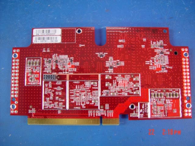
Click to zoom
Application Details
- Equipment Class
- DTS - Digital Transmission System
- Date of Grant
- Jul 31, 2007
- Application Purpose
- Original Equipment
- Date of Application
- Jul 30, 2007
- Equipment Note
- 2.4GHz 802.11b/g MIMO Radio Module
- Frequency Range
- 2412.00000000 - 2462.00000000
- Company
- Cisco Systems Inc
- Country
- United States
Documents & Files
Document Text
Text extracted from the exhibit documents filed with the FCC. Open a document above to read the original.
Users Manual
CISCO CONFIDENTIAL - Draft AA1 B-1 Cisco Aironet 1250 Series Access Point Hardware Installation Guide OL-8247-01 APPENDIX B Declarations of Conformity and Regulatory Information This appendix provides declarations of conformity and regulatory information for the Cisco Aironet 1250 Series Autonomous Access Point and the Cisco Aironet 1250 Series Lightweight Access Point. This appendix contains the following sections: •Manufacturers Federal Communication Commission Declaration of Conformity Statement, page B-2 •Department of Communications—Canada, page B-4 •European Community, Switzerland, Norway, Iceland, and Liechtenstein, page B-4 •Declaration of Conformity for RF Exposure, page B-7 •Guidelines for Operating Cisco Aironet Access Points in Japan, page B-8 •Administrative Rules for Cisco Aironet Access Points in Taiwan, page B-9 •Declaration of Conformity Statements, page B-11 •Declaration of Conformity Statements for European Union Countries, page B-11 CISCO CONFIDENTIAL - Draft AA1 B-2 Cisco Aironet 1250 Series Access Point Hardware Installation Guide OL-8247-01 Appendix B Declarations of Conformity and Regulatory Information Manufacturers Federal Communication Commission Declaration of Conformity Statement Manufacturers Federal Communication Commission Declaration of Conformity Statement Manufacturer: Cisco Systems, Inc. 170 West Tasman Drive San Jose, CA 95134-1706 USA This device complies with Part 15 rules. Operation is subject to the following two conditions: 1.This device may not cause harmful interference, and 2.This device must accept any interference received, including interference that may cause undesired operation. This equipment has been tested and found to comply with the limits of a Class B digital device, pursuant to Part 15 of the FCC Rules. These limits are designed to provide reasonable protection against harmful interference when the equipment is operated in a residential environment. This equipment generates, uses, and radiates radio frequency energy, and if not installed and used in accordance with the instructions, may cause harmful interference. However, there is no guarantee that interference will not occur. If this equipment does cause interference to radio or television reception, which can be determined by turning the equipment off and on, the user is encouraged to correct the interference by one of the following measures: •Reorient or relocate the receiving antenna. •Increase separation between the equipment and receiver. •Connect the equipment to an outlet on a circuit different from which the receiver is connected. •Consult the dealer or an experienced radio/TV technician. CautionThe Part 15 radio device operates on a non-interference basis with other devices operating at this frequency when using the integrated antennas. Any changes or modification to the product not expressly approved by Cisco could void the user’s authority to operate this device. ModelsCertification Numbers AIR-RM1252A-A-K9LDK102061 AIR-RM1252G-A-K9LDK102062 Tested To Comply With FCC Standard s FOR HOME OR OFFICE USE CISCO CONFIDENTIAL - Draft AA1 B-3 Cisco Aironet 1250 Series Access Point Hardware Installation Guide OL-8247-01 Appendix B Declarations of Conformity and Regulatory Information VCCI Statement for Japan CautionWithin the 5.15 to 5.25 GHz band (5 GHz radio channels 34 to 48) the UNII devices are restricted to indoor operations to reduce any potential for harmful interference to co-channel Mobile Satellite System (MSS) operations. VCCI Statement for Japan WarningThis is a Class B product based on the standard of the Voluntary Control Council for Interference from Information Technology Equipment (VCCI). If this is used near a radio or television receiver in a domestic environment, it may cause radio interference. Install and use the equipment according to the instruction manual. CISCO CONFIDENTIAL - Draft AA1 B-4 Cisco Aironet 1250 Series Access Point Hardware Installation Guide OL-8247-01 Appendix B Declarations of Conformity and Regulatory Information Department of Communications—Canada Department of Communications—Canada Canadian Compliance Statement This Class B Digital apparatus meets all the requirements of the Canadian Interference-Causing Equipment Regulations. Cet appareil numerique de la classe B respecte les exigences du Reglement sur le material broilleur du Canada. This device complies with Class B Limits of Industry Canada. Operation is subject to the following two conditions: 1.This device may not cause harmful interference, and 2.This device must accept any interference received, including interference that may cause undesired operation. Cisco Aironet 2.4-GHz Access Points are certified to the requirements of RSS-210 for 2.4-GHz spread spectrum devices, and Cisco Aironet 54-Mbps, 5-GHz Access Points are certified to the requirements of RSS-210 for 5-GHz spread spectrum devices.The use of this device in a system operating either partially or completely outdoors may require the user to obtain a license for the system according to the Canadian regulations. For further information, contact your local Industry Canada office. European Community, Switzerland, Norway, Iceland, and Liechtenstein Models: AIR-RM1252A-E-K9 AIR-RM1252G-E-K9 Certification Numbers 2461B-102061 2461B-102062 CISCO CONFIDENTIAL - Draft AA1 B-5 Cisco Aironet 1250 Series Access Point Hardware Installation Guide OL-8247-01 Appendix B Declarations of Conformity and Regulatory Information European Community, Switzerland, Norway, Iceland, and Liechtenstein Declaration of Conformity with Regard to the R&TTE Directive 1999/5/EC CISCO CONFIDENTIAL - Draft AA1 B-6 Cisco Aironet 1250 Series Access Point Hardware Installation Guide OL-8247-01 Appendix B Declarations of Conformity and Regulatory Information European Community, Switzerland, Norway, Iceland, and Liechtenstein This device complies with the EMC requirements (EN 60601-1-2) of the Medical Directive 93/42/EEC. For 2.4 GHz radios, the following st…
Text truncated - open the document above for the full version.
Cover Letter(s)
Jim Nicholson EMC Compliance Engineer Cisco Systems, Inc. 4125 Highlander Parkway Richfield, OH 44286 Phone: (330) 523-2094 Fax: (330) 523-2002 E-Mail: [email protected] July 18, 2005 Compliance Certification Services Certification Division 561F Monterey Road Morgan Hill, CA 95037 To whom it may concern: We, the undersigned, hereby authorize the Testing Division of Compliance Engineering Services, Inc., d.b.a. Compliance Certification Services and hereafter referred to as CCS, to act on our behalf in all manners relating to application for equipment authorization, including signing of all documents relating to these matters. Any and all acts carried out by CCS on our behalf shall have the same effect as acts of our own. We, the undersigned, hereby certify that we are not subject to a denial of federal benefits, that includes FCC benefits, pursuant to Section 5301 of the Anti-Drug Abuse Act of 1988, 21 U.S.C. 853(a). In authorizing CCS Testing Division as our agent, we still recognize that we are responsible to: a) comply with the relevant provisions of the certification program; b) make all necessary arrangements for the conduct of the evaluation, including provision for examining documentation and access to all areas, records (including internal audit reports) and personnel for the purposes of evaluation (e.g. testing, inspection, assessment, surveillance, reassessment) and resolution of complaints; c) make claims regarding certification only in respect of the scope for which certification has been granted; d) do not use our product certification in such a manner as to bring the Certification Division into disrepute and not make any statement regarding our product certification which the Certification Division may consider misleading or unauthorized; Jim Nicholson EMC Compliance Engineer Cisco Systems, Inc. 4125 Highlander Parkway Richfield, OH 44286 Phone: (330) 523-2094 Fax: (330) 523-2002 E-Mail: [email protected] e) upon suspension or cancellation of certification, discontinue use of all advertising matter that contains any reference thereto and return any certification documents as required by the Certification Division; f) use certification only to indicate the products are certified as being in conformity with specified standards; g) endeavor to ensure that no certificate or report nor any part thereof is used in a misleading manner; h) ensure that any reference to our product certification in communication media such as documents, brochures or advertising, complies with the requirements of the Certification Division; i) keep a record of all complaints made known to the us relating to the product’s compliance with requirements of the relevant standard and to make these records available to the Certification Division when requested; j) take appropriate action with respect to such complaints and any deficiencies found in products or services that affect compliance with the requirements for certification; k) document the actions taken. This authorization is valid until further written notice from the applicant. Best Regards, Jim Nicholson EMC Compliance Engineer
Cover Letter(s)
Jim Nicholson EMC Compliance Engineer Cisco Systems, Inc. 4125 Highlander Parkway Richfield, OH 44286 Phone: (330) 523-2094 Fax: (330) 523-2002 E-Mail: [email protected] February 20, 2007 Federal Communications Commission 7435 Oakland Mills Road Columbia MD 21046 Subject: Request for Confidentiality FCC ID: LDK102062 To Whom It May Concern: Pursuant to the provisions of Sections 0.457 and 0.459 of the Commission’s rules (47 CFR §§ 0.457, 0.459), we are requesting the Commission to withhold the following attachments as confidential documents from public disclosure indefinitely. Schematic Diagram Block Diagram Hardware Theory of Operation Best Regards, Jim Nicholson EMC Compliance Engineer
Cover Letter(s)
Jim Nicholson EMC Compliance Engineer Cisco Systems, Inc. 4125 Highlander Parkway Richfield, OH 44286 Phone: (330) 523-2094 Fax: (330) 523-2002 E-Mail: [email protected] February 20, 2007 Federal Communications Commission Equipment Authorization branch 7435 Oakland Mills Road Columbia, MD 21046 Re: FCC ID LDK102062: Request for Limited Modular Transmitter Approval To Whom It May Concern: Cisco Systems, Inc. hereby requests Modular Transmitter Approval for the above listed FCC submittal. In support of this request, please note the declarations listed below. 1. The modular transmitter has its own RF shielding and does not rely upon the shielding provided by the device into which it is installed in order to comply with Part 15 limits. 2. The modular transmitter has buffered modulation/data inputs and will comply with Part 15 requirements under conditions of excessive data rates or over-modulation. 3. The modular transmitter has its own power supply regulation, and will comply with Part 15 requirements regardless of the design of the power supplying circuitry in the device into which the module is installed. 4. The modular transmitter complies with the antenna requirements of Section 15.203 and 15.204(c). The modular transmitter employs a “unique” antenna coupler, and all antennas used with the module are being approved with the module. 5. The modular transmitter was tested in the access point in which it will solely operate. 6. The modular transmitter will be labeled with its own FCC ID number, and the outside of the device into which the module is installed will also display a label referring to the enclosed module. 7. The modular transmitter complies with the rules and operating requirements defined by Part 15.247. 8. The modular transmitter complies with all applicable RF exposure requirements. Best Regards, Jim Nicholson EMC Compliance Engineer Cisco Systems, Inc.
Cover Letter(s)
http://mail.google.com/mail/?ik=2a69a1bf8a&view=cv&search=inbox&th=112009712a95480c&ww=1131&lvp=0&cvp=5&qt=&zx=zc3j243gj4hd answer to FCC/IC questions: Cisco Systems, Inc., Certification No.: 2461B-102062 and LDK102062, Assessment NO.: AN07I1974 and AN07T6586 (07U10883) Inbox Reply from Claire Hoque <[email protected]> hide details 1:29 pm (1 hour ago) to Tim Dwyer - TCB <[email protected]>, "Timothy M. Dwyer" <[email protected]> cc Chi Tsou <[email protected]>, Christine Vu <[email protected]> date Apr 17, 2007 1:29 PM subject answer to FCC/IC questions: Cisco Systems, Inc., Certification No.: 2461B-102062 and LDK102062, Assessment NO.: AN07I1974 and AN07T6586 (07U10883) Hi Tim, Pls see answers below which apply to both FCC and IC. Grant defer-date is May 21. Thanks, Claire -----Original Message----- From: Timothy M. Dwyer Sent: Monday, March 12, 2007 9:46 AM To: Michael Heckrotte Cc: Timothy M. Dwyer Subject: Cisco Systems, Inc., Certification No.: 2461B-102062, Assessment NO.: AN07I1974, Notice#1 Hello Mike, Following are the items following review of the IC application. Please note that this list will be retransmitted as a second notice for the corresponding FCC application as it appears that the intent is to use the same report and other documentation for both applications. AN07I1974 Cisco 2461B-102062 Review Notes 1. Although the test report includes test parameters, it does not include reference to the specific standards and procedures employed. Please confirm that standards and procedures listed below were used in the testing of this product. Please either revise the test report or in this case it will be adequate to provide this confirmation via email. It is recommended that future test reports include specific references to the standards and procedures used. "Measurement of Digital Transmission Systems Operating under Section 15.247" FCC, March 23, 2005 ANSI C63.4-2003 <answer>Cisco confirms that the standards and procedures conform to the referenced document. 2. Page 23 of the test report includes reference to testing performed in the 5150-5725 MHz frequency range. This appears to be erroneous. Please revise the test report or provide additional explanation. <answer>revised test report is attached. 3. Page 8 of the test report refers to 5GHz average power that appears to be in error. Please revise. <answer>revised test report is attached. 4. Page 6 of the test report makes reference to Appendix E. The test report submitted has no Appendix E. Please revise the report. <answer>Cisco has removed the reference from the test report. 5. MIMO and Beamforming modes of operation are mentioned on page 5 of the test report. Please provide additional information in the test report, operational description or separate document relative to compliance with sections 15.247(c)(2)(i)-(iv) and the issues in the documents which can be accessed at the following URL's. http://www.fcc.gov/oet/ea/presentations/files/may05/Smart_Antenna_Systems_JD.pdf http://www.fcc.gov/oet/ea/presentations/files/oct04/Oct_04-Part_15_Updates-JD.pdf Specifically, provide information relative to the following: (a) number of beams formed <answer> When in beam forming mode, one beam is formed. (b) Confirm that the system uses Spatially Multiplexed MIMO technology only and not in combination with phased array or sectorized antennas. <answer> Most operating modes use only Spatially Multiplexed MIMO technology. Beam Forming is supported and covered in both the test report and theory of operation. (c) Confirm this is not a "Smart Antenna System" <answer> Beam Forming is supported and covered in both the test report and theory of operation. (d) Provide a block diagram and or description of how the test equipment was connected for output power, PPSD, and spurious measurements <answer> A photo of the conducted test setup is included in the test filing. It consists of the EUT connected to the spectrum analyzer through a combiner. http://mail.google.com/mail/?ik=2a69a1bf8a&view=cv&search=inbox&th=112009712a95480c&ww=1131&lvp=0&cvp=5&qt=&zx=zc3j243gj4hd (1 of 2)4/17/2007 3:01:46 PM http://mail.google.com/mail/?ik=2a69a1bf8a&view=cv&search=inbox&th=112009712a95480c&ww=1131&lvp=0&cvp=5&qt=&zx=zc3j243gj4hd (e) Whether simultaneous operation on multiple channels is possible and if so if this was investigated. <answer> Operation on only one channel at a time is possible. 6. The test setup photos show setups with co-located 2.4 and 5 GHz antennas. The EUT for radiated measurements has 6 rather than 3 antenna ports. No 5 GHz mode of operation information or 5 GHz measurement data (except spurious emissions) is included in the test report. Please provide additional information explaining the test modes and configuration. <answer>The 5 GHz radio shown in the test setup was submitted to the FCC in a separate filing(FCC ID: LDK102061). 7. The internal or external photos should show how and where connections are made to the antennas or antenna connectors. <answer> The antenna connections are clearly demonstrated in the Assembly Photos document included with the filing. 8. Please revise the user manual to include the following statements as required by IC RSS-GEN 7.1.4 and 7.1.5. "This device has been designed to operate with the antennas listed below, and having a maximum gain of [x] dB. Antennas not included in this list or having a gain greater than [x] dB are strictly prohibited for use with this device. The required antenna impedance is [y] ohms." "To reduce potential radio interference to other users, the antenna type and its gain should be so chosen that the equivalent isotropically radiated power (e.i.r.p.) is not more than that permitted for successful communication." <answer>Revised on page 5-2 of the attached manual. 9. The test report does not include receiver spurious emissions data as required by RSS-Gen Clause 4.8. Please revise the test report to include receiver measurements. <answer>Added to the attached …
Text truncated - open the document above for the full version.
External Photos
LDK102062 Label FCC label is on the back of the module PROPOSED FCC ID LABEL FOR HOST DEVICE CISCO SYSTEMS This device contains LDK102062
Parts List/Tune Up Info
3/25/2005 Coho 6 dBi Patch Technical Specification A printed version of this document is an uncontrolled copy. Cisco Systems, Inc. Page 1 of 7 Company Confidential Document Number: EDCS-399468 Revision: 2.0 Author: Steve Saliga Manager: Fred Anderson Coho 6 dBi Patch Antenna Specification (AIR-ANT2460P-R) Headline This document outlines the technical requirements for a 2.4 GHz, 6 dBi patch antenna that can be connected directly to a Cisco AP via an RP-TNC connector. This Cisco design is intended to replace an antenna that is procured from an outside supplier. 3/25/2005 Coho 6 dBi Patch Technical Specification A printed version of this document is an uncontrolled copy. Cisco Systems, Inc. Page 2 of 7 Company Confidential Approvals Name/Title Signature Date Fred Anderson Manager, RF Engineering Jim Mass Manager, Mechanical Engineering Jenny Adams Product Manager David Stiff Manager, Technical Marketing Jim Nicholson EMC Compliance Engineer Reviewers Name/Title Signature Date Mike Smedley Manager, WNBU NPI Manufacturing Tom Dirrig New Product Introduction Engineer Tony Winston Manager, Manufacturing Engineering Revision History Rev Date Author Comment 1.0 2/23/2005 Steve Saliga Initial Release, using simulated results for electrical specs 2.0 3/25/2005 Steve Saliga Updated the patterns and the electrical specs after prototyping. Also updated the physical size of the patch, the dielectric and the ground plane. 3/25/2005 Coho 6 dBi Patch Technical Specification A printed version of this document is an uncontrolled copy. Cisco Systems, Inc. Page 3 of 7 Company Confidential 1. Introduction This document describes the set of specifications for a single patch antenna to be used in the 2.4 GHz band. The basic features of this antenna are as follows: • Directional antenna for indoor/outdoor operation • RP-TNC Connector with 3-ft of plenum rated, cold temperature capable cable. • Operates over the entire 2.4 GHz band. • Peak gain is around 6 dBi In general, this antenna will be housed in a white polycarbonate radome very similar to the Coho AIR-ANT2485P-R. It will be built with 3 feet of off-white plenum rated cable and terminated in an RP-TNC. The specifications for this antenna will be presented sequentially with Electrical Specifications first, followed by Mechanical/Environmental Specifications and General Specifications. 2. Physical Appearance The actual antenna inside the radome is expected to be built on a fairly large ground plane of about 90 mm x 100 mm (3.5 in x 4.3 in). This large ground plane size allows for the use of a simple radome that fits over the ground plane rather than use two pieces of plastic to form the enclosure. This will lend itself to a (roughly) square radome that may look something like that shown in the preliminary drawing in Figure 2.1. Figure 2.1 Preliminary Industrial Design of the 6 dBi Patch Antenna 3/25/2005 Coho 6 dBi Patch Technical Specification A printed version of this document is an uncontrolled copy. Cisco Systems, Inc. Page 4 of 7 Company Confidential 3. 6 dBi Patch Antenna Specification This section contains both the electrical and mechanical specs for the Coho 6 dBi patch antenna. Basically, this is a single patch antenna built with a high density polyethylene dielectric over a ground plane. The antenna will have 3 feet of white/off-white plenum rated coaxial cable capable of operating down to -30 C. 3.1. Antenna Electrical Specifications and Patterns The electrical specifications for this antenna are summarized in Table 3.1.1 below. H- and E-plane patterns covering the whole band are shown in Figures 3.1.1.and 3.1.2. Note that the patterns include all cable loss as well as losses associated with a radome. 6 dBi Patch Antenna - Electrical Specifications Parameter Design Goal Minimum Acceptable Maximum Acceptable Notes 1 Antenna Type Single Patch Antenna 2 Operating Frequency Range 2400 MHz - 2484 MHz 3 Nominal Input Impedance 50 Ω 4 2:1 VSWR Bandwidth 2400 MHz – 2484 MHz 5 Peak Gain 6 dBi More like 6.5 dBi including Cable Loss 6 Polarization Linear, Vertical 7 E-Plane 3 dB Beamwidth 69 degrees 8 H-Plane 3-dB Beamwidth 75 degrees 9 F/B Ratio 18 dB 10 Cross-Pol Discrimination 15 dB Within the main beam. 11 Construction The antenna is a single patch built with a HDPE dielectric over a ground plane. The patch is about 40 mm W x 38.8 mm L and is formed from a single piece of brass. The feed is located 10.5 mm from the edge of the patch. The ground plane is 90 mm x 100 mm and is built from 2.6 mm thick aluminum. The dielectric is ¼” thick 12 Size 90 mm x 100 mm (3.5 in x 3.9 in) Table 3.1.1 Coho 6 dBi Patch Antenna, Electrical Specifications 3/25/2005 Coho 6 dBi Patch Technical Specification A printed version of this document is an uncontrolled copy. Cisco Systems, Inc. Page 5 of 7 Company Confidential Prototype H-Plane Patterns, AIR-ANT2460P-R 45 90 135 180 225 270 315 -25 -20 -15 -10 -5 0 5 10 Figure 3.1.1 AIR-ANT2460P-R, Prototype H-Plane Patterns Prototype E-Plane Patterns, AIR-ANT2460P-R 45 90 135 180 225 270 315 -25 -20 -15 -10 -5 0 5 10 Figure 3.1.2 AIR-ANT2460P-R, Prototype E-Plane Patterns 3/25/2005 Coho 6 dBi Patch Technical Specification A printed version of this document is an uncontrolled copy. Cisco Systems, Inc. Page 6 of 7 Company Confidential 3.2.Antenna Mechanical and Environmental Specifications The mechanical specifications will cover the physical appearance of the antenna as well as all mounting, cable and connectors. The mechanical and environmental specs are summarized in Table 3.2.1. 6 dBi Patch Antenna - Mechanical /Environmental Specifications Parameter Design Goal Minimum Acceptable Max Acceptable Notes 1 Radome Length 4.0 inches 2 Radome Width 3.6 inches 3 Radome Height < 1 inch 4 Radome Thickness 0.060 inches 5 Radome Material Lexan™ EXL 9330 6 Radome Color White GE Color #WH9B084 7 Antenna Dielectric 1/4” thick HDPE Color is opaque white 8 Cable Type Times AA-9303 or equivalent Plenum Rated, UV Stable, Cold Temperature Capable 9 …
Text truncated - open the document above for the full version.
Parts List/Tune Up Info
3/25/2005 Coho Diversity 6.5 dBi Patch Technical Specification A printed version of this document is an uncontrolled copy. Cisco Systems, Inc. Page 1 of 8 Company Confidential Document Number: EDCS-437825 Revision: 2.0 Author: Steve Saliga Manager: Fred Anderson Coho Diversity 6.5 dBi Patch Antenna Specification (AIR-ANT2465P-R) Headline This document outlines the technical requirements for a 2.4 GHz, diversity 6.5 dBi patch antenna that can be connected directly to a Cisco AP via an RP-TNC connector. 3/25/2005 Coho Diversity 6.5 dBi Patch Technical Specification A printed version of this document is an uncontrolled copy. Cisco Systems, Inc. Page 2 of 8 Company Confidential Approvals Name/Title Signature Date Fred Anderson Manager, RF Engineering Jim Mass Manager, Mechanical Engineering Jenny Adams Product Manager David Stiff Manager, Technical Marketing Jim Nicholson EMC Compliance Engineer Reviewers Name/Title Signature Date Mike Smedley Manager, WNBU NPI Manufacturing Tom Dirrig New Product Introduction Engineer Tony Winston Manager, Manufacturing Engineering Revision History Rev Date Author Comment 1.0 3/18/2005 Steve Saliga Initial Release, using simulated and prototype results for electrical specs 2.0 3/25/2005 Steve Saliga Updates the dimensions of the patch. 3/25/2005 Coho Diversity 6.5 dBi Patch Technical Specification A printed version of this document is an uncontrolled copy. Cisco Systems, Inc. Page 3 of 8 Company Confidential 1. Introduction This document describes the set of specifications for a diversity patch antenna to be used in the 2.4 GHz band. The basic features of this antenna are as follows: • Directional antenna for indoor/outdoor operation • RP-TNC Connector with 3-ft of plenum rated, cold temperature capable cable. • Operates over the entire 2.4 GHz band. • Peak gain is around 6.5 dBi In general, this antenna will be housed in a white polycarbonate radome very similar to the Coho AIR-ANT2485P-R except that there will be two cables. It will be built with 3 feet of off-white plenum rated cable and terminated in an RP-TNC. The specifications for this antenna will be presented sequentially with Electrical Specifications first, followed by Mechanical/Environmental Specifications and General Specifications. 2. Physical Appearance The actual antenna inside the radome is expected to be built on a fairly large ground plane of about 110 mm x 165 mm (3.94 in x 6.5 in). This large ground plane size allows for the placement of two patches over the same ground plane as well as the use of a simple radome that fits over the ground plane rather than use two pieces of plastic to form the enclosure. This will lend itself to a rectangular radome of about 110 mm x 165 mm x 25 mm. The actual antennas will be arranged on the ground plane as shown in Figure 2.1. The radome has not been designed at this time. Figure 2.1 Simulated Model of AIR-ANT2465P-R 3/25/2005 Coho Diversity 6.5 dBi Patch Technical Specification A printed version of this document is an uncontrolled copy. Cisco Systems, Inc. Page 4 of 8 Company Confidential 3. Diversity 6.5 dBi Patch Antenna Specification This section contains both the electrical and mechanical specs for the Coho diversity 6.5 dBi patch antenna. Basically, this package contains two patch antennas built with an air dielectric over a ground plane. The antenna will have 3 feet of white/off-white plenum rated coaxial cable capable of operating down to -30 C. 3.1. Antenna Electrical Specifications and Patterns The electrical specifications for this antenna are summarized in Table 3.1.1 below. H- and E-plane patterns are shown in Figures 3.1.1.and 3.1.2. Note that the patterns shown include all cable losses as well as the losses associated with a hand built radome. Diversity 6.5 dBi Patch Antenna - Electrical Specifications Parameter Design Goal Minimum Acceptable Maximum Acceptable Notes 1 Antenna Type Diversity Patch Antenna Two antennas in the same package 2 Operating Frequency Range 2400 MHz - 2484 MHz 3 Nominal Input Impedance 50 Ω 4 2:1 VSWR Bandwidth 2400 MHz – 2484 MHz 5 Peak Gain 6.5 dBi 6 Polarization Linear, Vertical 7 E-Plane 3 dB Beamwidth 65 degrees Based on Single Antenna 8 H-Plane 3-dB Beamwidth 75 degrees Based on single antenna 9 F/B Ratio 15 dB 10 Cross-Pol Discrimination 15 dB Within the main beam. 11 Construction There are two antennas housed in a single radome, each with its own feed cable. Each patch is built with an air dielectric over the ground plane. Each patch is 40 mm W x 51 mm L and is formed from a single piece of brass. The ground plane is 110 mm x 165 mm and is built from 2.6 mm thick aluminum. The patches are placed 7 mm above the ground plane. 12 Size 110 mm x 165 mm (4.3 in x 6.5 in) Table 3.1.1 Coho 6 dBi Patch Antenna, Electrical Specifications 3/25/2005 Coho Diversity 6.5 dBi Patch Technical Specification A printed version of this document is an uncontrolled copy. Cisco Systems, Inc. Page 5 of 8 Company Confidential H-Plane Patterns, AIR-ANT2465P-R Right Antenna 30 60 90 120 150 180 210 240 270 300 330 -25 -20 -15 -10 -5 0 5 10 Figure 3.1.1 AIR-ANT2465P-R, Prototype H-Plane Patterns Right Antenna E-Plane Patterns, AIR-ANT2465P-R Right Antenna 30 60 90 120 150 180 210 240 270 300 330 -25 -20 -15 -10 -5 0 5 10 Figure 3.1.2 AIR-ANT2465P-R, Prototype E-Plane Patterns Right Antenna 3/25/2005 Coho Diversity 6.5 dBi Patch Technical Specification A printed version of this document is an uncontrolled copy. Cisco Systems, Inc. Page 6 of 8 Company Confidential H-Plane Patterns, AIR-ANT2465P-R Left Antenna 30 60 90 120 150 180 210 240 270 300 330 -25 -20 -15 -10 -5 0 5 10 Figure 3.1.3 AIR-ANT2465P-R, Prototype H-Plane Patterns Left Antenna E-Plane Patterns, AIR-ANT2465P-R Left Antenna 30 60 90 120 150 180 210 240 270 300 330 -25 -20 -15 -10 -5 0 5 10 Figure 3.1.4 AIR-ANT2465P-R, Prototype E-Plane Patterns Left Antenna 3/25/2005 Coho Diversity 6.5 dBi Patch Technical Specification A printed version of this document is an uncontroll…
Text truncated - open the document above for the full version.
Parts List/Tune Up Info
9/13/2006 Salar 2.4 GHz 802.11n Ceiling Mount Omni Specification A printed version of this document is an uncontrolled copy. Cisco Systems, Inc…
Text truncated - open the document above for the full version.
Contact Information
Applicant
Samuel Kim(Manager, Engineering)
Technical Contact
COMPLIANCE CERTIFICATION SERVICESMichael Heckrotte
[email protected](510) 771-1000
47174 Benicia Street · Fremont, California · United States
Non-Technical Contact
COMPLIANCE CERTIFICATION SERVICESMichael Heckrotte
[email protected](510) 771-1000
Test Firm
Compliance Certification ServicesThu Chan
Technical Specifications
| # | Rule Parts | Frequency Range | Power Output |
|---|---|---|---|
| 1 | 15C | 2.41 GHz - 2.46 GHz | 199.50 mW |
Other Applications from Cisco Systems Inc

LDKJ98213058
May 25, 2026Wireless Phone
Equipment Class
DSS - Part 15 Spread Spectrum TransmitterLDKIW9165E
Aug 20, 2024Wi-Fi 6E Outdoor Access Point
Equipment Class
6SD - 15E 6 GHz Standard Power Access PointLDKIW9165DH
Aug 05, 2024Wi-Fi 6E Outdoor Access Point
Equipment Class
6SD - 15E 6 GHz Standard Power Access PointLDKUSBC2857
Jul 22, 2024Cisco Headset USB-C Adapter
Equipment Class
DSS - Part 15 Spread Spectrum TransmitterLDKESPRD2922
May 09, 2024UC Phone
Equipment Class
NII - Unlicensed National Information Infrastructure TX