LDK102063802.11a Radio Module
Cisco Systems Inc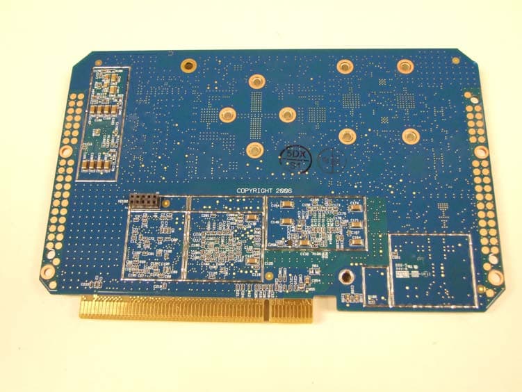
Click to zoom
Application Details
- Equipment Class
- DTS - Digital Transmission System
- Date of Grant
- Jul 19, 2007
- Application Purpose
- Original Equipment
- Date of Application
- Apr 04, 2007
- Equipment Note
- 802.11a Radio Module
- Frequency Range
- 5745.00000000 - 5825.00000000
- Company
- Cisco Systems Inc
- Country
- United States
Documents & Files
Document Text
Text extracted from the exhibit documents filed with the FCC. Open a document above to read the original.
Users Manual
CHAPTER CISCO CONFIDENTIAL - Draft 1 1-1 Cisco Aironet 1520 Series Outdoor Mesh Access Point Hardware Installation Guide OL-12632-01 1 Overview The Cisco Aironet 1520 Series Outdoor Mesh Access Point (hereafter called the access point) is a wireless device designed for wireless client access, point-to-point bridging, point-to-multipoint bridging, and point-to-multipoint mesh wireless connectivity. The access point is a standalone unit that can be mounted on a streetlight pole or on a building wall or overhang. It is a self-contained outdoor unit that can be configured with a wired backhaul connection to an Ethernet segment for a rooftop deployment or can be configured with a wireless backhaul for a pole-top deployment. The access point can be installed where power is available without the need for a wired network connection. The access point is available in two models: LAP1522 (supports 2.4-GHz and 5-GHz radios) and LAP1521 (supports a 2.4-GHz radio).The access point provides client access and wireless mesh backhaul that supports 6 to 54 Mbps data rates without the need for a license. The LAP1522 model dedicates the 5-GHz radio for backhaul operations to reach a wired network and uses the 2.4-GHz radio for wireless clients. The LAP1521 model uses the 2.4- or 5-GHz radio for both backhaul and wireless clients. The access point can also operate as a relay node for other access points not directly connected to a wired network. Intelligent wireless routing is provided by the patent-pending Adaptive Wireless Path Protocol (AWPP). This enables each access point to identify its neighbors and intelligently choose the optimal path to the wired network by calculating the cost of each path in terms of signal strength and the number of hops required to get to a controller. The access point is configured, monitored, and operated through a Cisco wireless LAN controller (hereafter called a controller) as described in the Cisco Wireless LAN Controller Configuration Guide. The Deployment Guide: Cisco Mesh Networking Solution describes how to plan and initially configure the Cisco Mesh network, which supports wireless point-to-point, point-to-multipoint, and mesh deployments. The controllers use a browser-based management system, a command-line interface (CLI), or the Cisco Wireless Control System (WCS) network management system to manage the controller and the associated access points. The access point is compliant with Wi-Fi Protected Access (WPA2) and employs hardware-based Advanced Encryption Standard (AES) encryption between wireless nodes to provide end-to-end security. This chapter provides information on the following topics: •Main Hardware Features, page 2 •Network Configuration Examples, page 6 2 Overview OL-12632-01 Main Hardware Features Some of the access point’s main hardware features are listed below: •One or two radios (2.4- and 5-GHz)—see the “Single or Dual Radio Operation” section on page 3 •External radio antennas—see the “External Antennas” section on page 3 •Multiple power sources—see the “Multiple Power Sources” section on page 4 •Rugged metal enclosure—see the “Metal Enclosure” section on page 5 •Optional Ethernet ports—see the “Ethernet Ports” section on page 5 •Optional cable modem—see the •Optional hardware—see the “Optional Hardware” section on page 6 –Cable strand mount kit –Pole mount kit –150 ft (45.72 m) Ethernet outdoor cable •Optional battery backup—future availability Figure 1 shows the access point connectors. Figure 1Access Point Connectors 14 25 36 Connectors The optional featues of the access point support these connectors (see Figure 1): •Ethernet (PoE) uplink connector—(type RJ45 with TBD for waterproofing) •Ethernet downlink connector—(type RJ45 with TBD for waterproofing) •Three Type N antenna connectors (2.4-GHz radio) •One Type N antenna connector (5-GHz radio) •Fiber-optic connector—Small form factor pluggable (SFP) •Power-over-cable (POC) connector—(TBD) •AC power connector Single or Dual Radio Operation The access point is available in two models: LAP1522 (supports 2.4-GHz and 5-GHz radios) and LAP1521 (supports a 2.4- or 5-GHz radio). The radios use external antennas (see “External Antennas”). The LAP1522 model supports simultaneous dual-radio operation using a 2.4-GHz 802.11b/g radio and a 5-GHz 802.11a radio. The LAP1521 model supports both mesh backhaul operation and wireless clients using a single 2.4- or 5-GHz radio. The 5-GHz radio incorporates an Unlicensed National Information Infrastructure (UNII) radio transceiver operating in the UNII 5-GHz frequency bands. The 5-GHz radio on the access point is used for backhaul operations to the controller. The 5-GHz radio can also operate in the 4.9-GHz Public Safety band in the United States. NoteThe 4.9-GHz band requires a license and may be used only by qualified Public Safety operators as defined in section 90.20 of the FCC rules. The 2.4-GHz radio supports three antennas for multi-input, single output (MISO) operation. The radio uses three receivers to support maximum ratio combining (MRC) to enhance receiver performance. MRC is a technique that combines the signals from multiple receivers in a manner to optimize the signals. MRC can provide up to 3 dB of increased receive signal strength. The access point does not support both radios configured for backhaul support External Antennas The access point is equipped with three N-type radio frequency (RF) connector on the top of the unit for external 2.4-GHz antennas to support multiple input single output (MISO) operation. The LAP1522 model also has one to three N-type RF connectors on the bottom of the unit for external 5-GHz antennas (see Figure 1). When using the optional Cisco compact omnidirectional antennas, the 2.4- and 5-GHz antennas connect directly to the access point. The Cisco omnidirectional antennas use vertical polarization. The access point can also be equipped with specific third-party external antennas (see Table 1 and Table 2), subject to l…
Text truncated - open the document above for the full version.
Cover Letter(s)
Jim Nicholson EMC Compliance Engineer Cisco Systems, Inc. 4125 Highlander Parkway Richfield, OH 44286 Phone: (330) 523-2094 Fax: (330) 523-2002 E-Mail: [email protected] April 4, 2007 Federal Communications Commission 7435 Oakland Mills Road Columbia MD 21046 Subject: Request for Confidentiality FCC ID: LDK102063 To Whom It May Concern: Pursuant to the provisions of Sections 0.457 and 0.459 of the Commission’s rules (47 CFR §§ 0.457, 0.459), we are requesting the Commission to withhold the following attachments as confidential documents from public disclosure indefinitely. Schematic Diagram Block Diagram Hardware Theory of Operation Software Theory of Operation Best Regards, Jim Nicholson EMC Compliance Engineer
Cover Letter(s)
Jim Nicholson EMC Compliance Engineer Cisco Systems, Inc. 4125 Highlander Parkway Richfield, OH 44286 Phone: (330) 523-2094 Fax: (330) 523-2002 E-Mail: [email protected] April 4, 2007 Federal Communications Commission Equipment Authorization branch 7435 Oakland Mills Road Columbia, MD 21046 Re: FCC ID LDK102063: Request for Limited Modular Transmitter Approval To Whom It May Concern: Cisco Systems, Inc. hereby requests Modular Transmitter Approval for the above listed FCC submittal. In support of this request, please note the declarations listed below. 1. The modular transmitter has its own RF shielding and does not rely upon the shielding provided by the device into which it is installed in order to comply with Part 15 limits. 2. The modular transmitter has buffered modulation/data inputs and will comply with Part 15 requirements under conditions of excessive data rates or over-modulation. 3. The modular transmitter has its own power supply regulation, and will comply with Part 15 requirements regardless of the design of the power supplying circuitry in the device into which the module is installed. 4. The modular transmitter complies with the antenna requirements of Section 15.203 and 15.204(c). The modular transmitter employs a “unique” antenna coupler, and all antennas used with the module are being approved with the module. 5. The modular transmitter was tested in the access point in which it will solely operate. 6. The modular transmitter will be labeled with its own FCC ID number, and the outside of the device into which the module is installed will also display a label referring to the enclosed module. 7. The modular transmitter complies with the rules and operating requirements defined by Part 15.247 and Part 15.407. 8. The modular transmitter complies with all applicable RF exposure requirements. Best Regards, Jim Nicholson EMC Compliance Engineer Cisco Systems, Inc.
Cover Letter(s)
Jim Nicholson EMC Compliance Engineer Cisco Systems, Inc. 4125 Highlander Parkway Richfield, OH 44286 Phone: (330) 523-2094 Fax: (330) 523-2002 E-Mail: [email protected] May 18, 2007 Federal Communications Commission 7435 Oakland Mills Road Columbia MD 21046 Subject: Grant Issuance Delay FCC ID: LDK102063 To Whom It May Concern: The 731 forms (EA550208, EA666654, and EA731174) for FCC ID: LDK102063 requested that the grant be issued on June 15, 2007. Cisco now requests that issuance of this grant be delayed until July 11, 2007. Best Regards, Jim Nicholson EMC Compliance Engineer
External Photos
External Photos AIR-RM1520A Shielded Top AIR-RM1520A Bottom AIR-RM1520A Bottom with Heat Sink AIR-RM1520A Regulatory Label AIR-RM1520A Installed in AIR-LAP1522AG Housing AIR-LAP1522AG Assembled Housing AIR-LAP1522AG Regulatory Label Location AIR-LAP1522AG Regulatory Label
ID Label/Location Info
External Photos AIR-RM1520A Shielded Top AIR-RM1520A Bottom AIR-RM1520A Bottom with Heat Sink AIR-RM1520A Regulatory Label AIR-RM1520A Installed in AIR-LAP1522AG Housing AIR-LAP1522AG Assembled Housing AIR-LAP1522AG Regulatory Label Location AIR-LAP1522AG Regulatory Label
Internal Photos
Internal Photos AIR-RM1520A Unshielded Top AIR-RM1520A Unshielded Bottom
Test Report
Custom EMC Test Report No: EDCS - 582732 Page No: 1 of 37 This document is uncontrolled. Please refer to the electronic copy within EDCS for the most up to date version. Cisco Systems, Inc. Company Confidential ISM Test Report AIR-RM1520A-A-K9 802.11a Radio Module FCC ID: LDK102063 Against the following Specifications: CFR47 Part 15.247 RSS210 Cisco Systems 170 West Tasman Drive San Jose, CA 95134 Author: James Nicholson Approved By: Title: Custom EMC Test Report No: EDCS - 582732 Page No: 2 of 37 This document is uncontrolled. Please refer to the electronic copy within EDCS for the most up to date version. Cisco Systems, Inc. Company Confidential This test report has been electronically authorized and archived using the CISCO Engineering Document Control system. SECTION 1: OVERVIEW .........................................................................................................................................3 1.1 TEST SUMMARY......................................................................................................................................... 3 SECTION 2: ASSESSMENT INFORMATION......................................................................................................4 2.1 GENERAL.................................................................................................................................................. 4 2.4 TESTING FACILITIES................................................................................................................................... 5 2.6 EUT DESCRIPTION.................................................................................................................................... 5 SECTION 3: SAMPLE DETAILS.............................................................................................................................6 APPENDIX A: EMISSION TEST RESULTS ..................................................................................................7 APPENDIX B: EMISSION TEST RESULTS ................................................................................................19 APPENDIX C: ABBREVIATION KEY AND DEFINITIONS ......................................................................35 APPENDIX E: TEST EQUIPMENT/SOFTWARE USED TO PERFORM THE TEST ............................36 APPENDIX E: TEST EQUIPMENT/SOFTWARE USED TO PERFORM THE TEST ............................36 Custom EMC Test Report No: EDCS - 582732 Page No: 3 of 37 This document is uncontrolled. Please refer to the electronic copy within EDCS for the most up to date version. Cisco Systems, Inc. Company Confidential Section 1: Overview 1.1 Test Summary samples were assessed against the tests detailed in section 3 under the requirements of the following specifications: Emission Immunity CFR47 Part 15.247(a) CFR47 Part 15.247(a)(2) CFR47 Part 15.247a3 (RSS210) CFR47 Part 15: 2005 CFR47 Part 15: 2005 (CAN/CSA-CISPR 22-02) N/A The specifications listed above represent actual tests performed to demonstrate compliance against the specifications and basic standards listed on the front cover of this report. This list is not a one to one match to the front cover for one or more of the following reasons. 1. Basic standards call up many different test phenomena specifications such as the 61000-4-X series. The basic standards define which elements and levels shall be applied from these specifications and as such it is not appropriate to list the individual specifications on the front cover. 2. A Standard listed on the front cover may be required in a particular country but is not appropriate for the particular technologies included in the equipment under test. E.g. You cannot test a DC product to the mains Harmonics requirements in EN61000-3-2. See section 3.2. 3. Test results against a particular standard or specification may be included in a different test report. See section 3.2 for an EDCS reference of this data. 4. Where appropriate, Cisco may have substituted a later revision of a basic standard to those referenced in the specification on the front sheet of this test report. This decision was based upon improved test methodology and repeatability and/or where the newer revision represented a more stringent test. 5. Where relevant, testing has been carried out to the requirements of both EN and IEC Specifications. This was possible because of the similarities of the test methods involved and the Cisco EMC test procedures. 6. Testing may have been performed to an equivalent test that satisfies the requirements of the standards and specifications listed on the front cover of the report. See section 3.2. 7. Where radiated emissions testing has been performed to EN55022/CISPR22 the additional requirements of VCCI: V- 3/2006.04, EN55022: 1994 +A1/2 and CAN/CSA- CISPR 22-02 have also been evaluated unless otherwise stated. 8. Testing to the requirements of CFR47 Part 15 was performed against the CISPR22 limits. The results are therefore deemed satisfactory evidence of compliance with Industry Canada Interference Causing Equipment Standard ICES-003. 9. Where assessment has been performed to CISPR24, all the applicable test requirements may have not been covered. Refer to the results section for the tests performed. Notes: 1) Where a specification listed on the front cover of this report has deviations from the basic standards listed above, the additional technical requirements of the specification were also assessed. 2) Where appropriate, Cisco may have substituted a later revision of a basic standard to those referenced in the specification on the front sheet of this test report. This decision was based upon improved test methodology and repeatability and/or where the newer revision represented a more stringent test. 3) Where relevant, testing has been carried out to the requirements of both EN and IEC Specifications. This was possible because of the similarities of the test methods involved and the Cisco EMC test procedures. Custom EM…
Text truncated - open the document above for the full version.
Test Setup Photos
Test Setup Photos Radiated Emissions, 5GHz 8dBi Omni Antenna with 2.4GHz 6dBi Omni Antenna Radiated Emissions, 5GHz 8dBi Omni Antenna with 2.4GHz 8dBi Omni Antenna Radiated Emissions, 5GHz 14dBi Patch Antenna with 2.4GHz 8dBi Omni Antenna Radiated Emissions, 5GHz 14dBi Patch Antenna with 2.4GHz 8dBi Omni Antenna Radiated Emissions, 5GHz 17dBi Sector Antenna with 2.4GHz 8dBi Omni Antenna Radiated Emissions, 5GHz 17dBi Sector Antenna with 2.4GHz 8dBi Omni Antenna Unintentional 30MHz-1GHz Radiated Emissions, 5GHz 17dBi Sector Antenna with 2.4GHz 8dBi Omni Antenna Conducted Powerline Emissions
Contact Information
Applicant
Samuel Kim(Manager, Engineering)
Technical Contact
Cisco SystemsJim Nicholson
[email protected]3305232094
4125 Highlander Parkway · Richfield, Ohio · United States
Test Firm
Cisco Systems, Inc.Dave Wilson
Technical Specifications
| # | Rule Parts | Frequency Range | Power Output | Tolerance |
|---|---|---|---|---|
| 1 | 15C | 5.75 GHz - 5.83 GHz | 500.00 mW | 20.0000000000 ppm |
Other Applications from Cisco Systems Inc

LDKJ98213058
May 25, 2026Wireless Phone
Equipment Class
DSS - Part 15 Spread Spectrum TransmitterLDKIW9165E
Aug 20, 2024Wi-Fi 6E Outdoor Access Point
Equipment Class
6SD - 15E 6 GHz Standard Power Access PointLDKIW9165DH
Aug 05, 2024Wi-Fi 6E Outdoor Access Point
Equipment Class
6SD - 15E 6 GHz Standard Power Access PointLDKUSBC2857
Jul 22, 2024Cisco Headset USB-C Adapter
Equipment Class
DSS - Part 15 Spread Spectrum TransmitterLDKESPRD2922
May 09, 2024UC Phone
Equipment Class
NII - Unlicensed National Information Infrastructure TX