LDK1020674.9GHz Radio Module
Cisco Systems Inc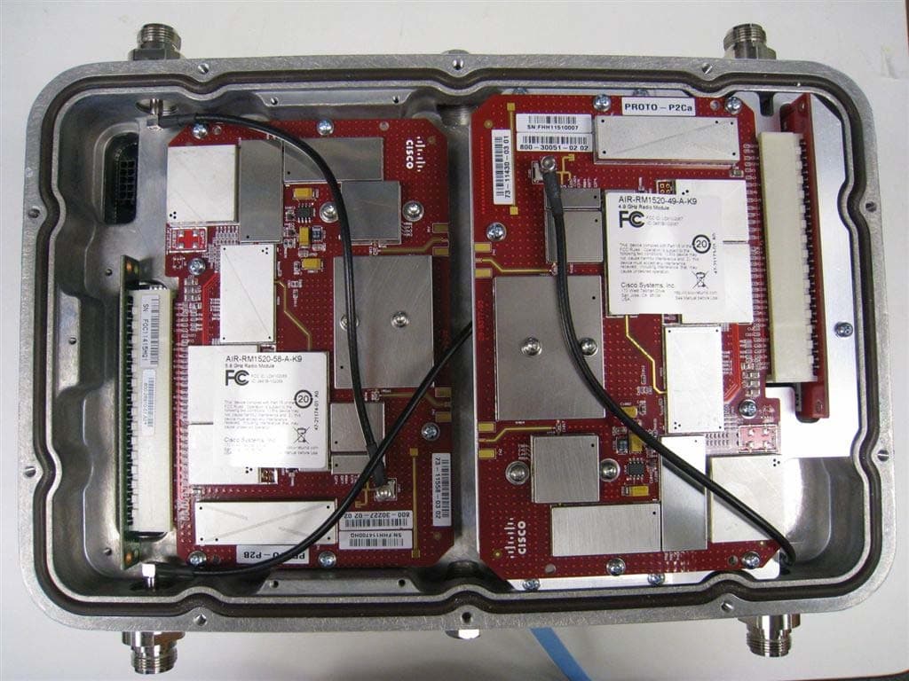
Click to zoom
Application Details
- Equipment Class
- TNB - Licensed Non-Broadcast Station Transmitter
- Date of Grant
- Jan 30, 2008
- Application Purpose
- Original Equipment
- Date of Application
- Jan 30, 2008
- Equipment Note
- 4.9GHz Radio Module
- Frequency Range
- 4950.00000000 - 4980.00000000
- Company
- Cisco Systems Inc
- Country
- United States
Documents & Files
Document Text
Text extracted from the exhibit documents filed with the FCC. Open a document above to read the original.
Users Manual
REVIEW DRAFT—CISCO CONFIDENTIAL Americas Headquarters Cisco Systems, Inc. 170 West Tasman Drive San Jose, CA 95134-1706 USA http://www.cisco.com Tel: 408 526-4000 800 553-NETS (6387) Fax: 408 527-0883 Cisco Aironet 1520 Series Outdoor Mesh Access Point Hardware Installation Guide March, 2008 Text Part Number: OL-12632-03 REVIEW DRAFT—CISCO CONFIDENTIAL THE SPECIFICATIONS AND INFORMATION REGARDING THE PRODUCTS IN THIS MANUAL ARE SUBJECT TO CHANGE WITHOUT NOTICE. ALL STATEMENTS, INFORMATION, AND RECOMMENDATIONS IN THIS MANUAL ARE BELIEVED TO BE ACCURATE BUT ARE PRESENTED WITHOUT WARRANTY OF ANY KIND, EXPRESS OR IMPLIED. USERS MUST TAKE FULL RESPONSIBILITY FOR THEIR APPLICATION OF ANY PRODUCTS. THE SOFTWARE LICENSE AND LIMITED WARRANTY FOR THE ACCOMPANYING PRODUCT ARE SET FORTH IN THE INFORMATION PACKET THAT SHIPPED WITH THE PRODUCT AND ARE INCORPORATED HEREIN BY THIS REFERENCE. IF YOU ARE UNABLE TO LOCATE THE SOFTWARE LICENSE OR LIMITED WARRANTY, CONTACT YOUR CISCO REPRESENTATIVE FOR A COPY. The following information is for FCC compliance of Class A devices: This equipment has been tested and found to comply with the limits for a Class A digital device, pursuant to part 15 of the FCC rules. These limits are designed to provide reasonable protection against harmful interference when the equipment is operated in a commercial environment. This equipment generates, uses, and can radiate radio-frequency energy and, if not installed and used in accordance with the instruction manual, may cause harmful interference to radio communications. Operation of this equipment in a residential area is likely to cause harmful interference, in which case users will be required to correct the interference at their own expense. The following information is for FCC compliance of Class B devices: The equipment described in this manual generates and may radiate radio-frequency energy. If it is not installed in accordance with Cisco’s installation instructions, it may cause interference with radio and television reception. This equipment has been tested and found to comply with the limits for a Class B digital device in accordance with the specifications in part 15 of the FCC rules. These specifications are designed to provide reasonable protection against such interference in a residential installation. However, there is no guarantee that interference will not occur in a particular installation. Modifying the equipment without Cisco’s written authorization may result in the equipment no longer complying with FCC requirements for Class A or Class B digital devices. In that event, your right to use the equipment may be limited by FCC regulations, and you may be required to correct any interference to radio or television communications at your own expense. You can determine whether your equipment is causing interference by turning it off. If the interference stops, it was probably caused by the Cisco equipment or one of its peripheral devices. If the equipment causes interference to radio or television reception, try to correct the interference by using one or more of the following measures: • Turn the television or radio antenna until the interference stops. • Move the equipment to one side or the other of the television or radio. • Move the equipment farther away from the television or radio. • Plug the equipment into an outlet that is on a different circuit from the television or radio. (That is, make certain the equipment and the television or radio are on circuits controlled by different circuit breakers or fuses.) Modifications to this product not authorized by Cisco Systems, Inc. could void the FCC approval and negate your authority to operate the product. The Cisco implementation of TCP header compression is an adaptation of a program developed by the University of California, Berkeley (UCB) as part of UCB’s public domain version of the UNIX operating system. All rights reserved. Copyright © 1981, Regents of the University of California. NOTWITHSTANDING ANY OTHER WARRANTY HEREIN, ALL DOCUMENT FILES AND SOFTWARE OF THESE SUPPLIERS ARE PROVIDED “AS IS” WITH ALL FAULTS. CISCO AND THE ABOVE-NAMED SUPPLIERS DISCLAIM ALL WARRANTIES, EXPRESSED OR IMPLIED, INCLUDING, WITHOUT LIMITATION, THOSE OF MERCHANTABILITY, FITNESS FOR A PARTICULAR PURPOSE AND NONINFRINGEMENT OR ARISING FROM A COURSE OF DEALING, USAGE, OR TRADE PRACTICE. IN NO EVENT SHALL CISCO OR ITS SUPPLIERS BE LIABLE FOR ANY INDIRECT, SPECIAL, CONSEQUENTIAL, OR INCIDENTAL DAMAGES, INCLUDING, WITHOUT LIMITATION, LOST PROFITS OR LOSS OR DAMAGE TO DATA ARISING OUT OF THE USE OR INABILITY TO USE THIS MANUAL, EVEN IF CISCO OR ITS SUPPLIERS HAVE BEEN ADVISED OF THE POSSIBILITY OF SUCH DAMAGES. Any Internet Protocol (IP) addresses used in this document are not intended to be actual addresses. Any examples, command display output, and figures included in the document are shown for illustrative purposes only. Any use of actual IP addresses in illustrative content is unintentional and coincidental. Book Title ©2007 Cisco Systems, Inc. All rights reserved. CCSP, the Cisco Square Bridge logo, Follow Me Browsing, and StackWise are trademarks of Cisco Systems, Inc.; Changing the Way We Work, Live, Play, and Learn, and i Study are service marks of Cisco Systems, Inc.; and Access Registrar, Aironet, ASIST, BPX, Catalyst, CCDA, CCDP, CCIE, CCIP, CCNA, CCNP, Cisco, the Cisco Certifie Internetwork Expert logo, Cisco IOS, Cisco Press, Cisco Systems, Cisco Systems Capital, the Cisco Systems logo, Cisco Unity, Empowering the Internet Generation, Enterprise/Solver, EtherChannel, EtherFast, EtherSwitch, Fast Step, FormShare, GigaDrive, GigaStack, HomeLink, Internet Quotient, IOS, IP/TV, iQ Expertise, the iQ log o Net Readiness Scorecard, LightStream, Linksys, MeetingPlace, MGX, the Networkers logo, Networking Academy, Network Registrar, Packet, PIX, Post-Routing, Pre-Rout ProConnect, RateMUX, ScriptShare, SlideCast, SMARTnet, StrataView Plus, SwitchProbe, TeleRouter, The Fastest W…
Text truncated - open the document above for the full version.
Users Manual
REVIEW DRAFT—CISCO CONFIDENTIAL 2-21 Cisco Aironet 1520 Series Outdoor Mesh Access Point Hardware Installation Guide OL-12632-03 Chapter 2 Mounting Instructions Mounting the Access Point Mounting the Access Point on a Pole When installing an access point on a vertical pole, mast, or a streetlight pole, you should use the optional Cisco pole mount kit. The kit supports metal, wood, or fiberglass poles from 2 to 16 inches in diameter. Assembling the Pole Clamp Bracket and the Mounting Bracket When installing an access point on a pole, mast, or a streetlight, you should use the optional Cisco pole mount kit. The kit supports metal, wood, or fiberglass poles from 2 to 16 inches in diameter. The pole mount kit contains several parts that you must assembled prior to mounting on a pole. First you need to assemble two strap brackets on the pole clamp bracket that are positioned for the pole diameter you are using to mount the access point. Figure 2-9 illustrates the pole diameter indicators and bolt holes on the pole clamp bracket. REVIEW DRAFT—CISCO CONFIDENTIAL 2-22 Cisco Aironet 1520 Series Outdoor Mesh Access Point Hardware Installation Guide OL-12632-03 Chapter 2 Mounting Instructions Mounting the Access Point Figure 2-9Pole Clamp Bracket Adjustment Hole Locations 1Pole size indicators •2 to 6 in. •6 to 11 in. •11 to 16 in. 2Bolt holes for pole diameters (11 to 16 inches indicated) REVIEW DRAFT—CISCO CONFIDENTIAL 2-23 Cisco Aironet 1520 Series Outdoor Mesh Access Point Hardware Installation Guide OL-12632-03 Chapter 2 Mounting Instructions Mounting the Access Point To assemble the pole clamp bracket, perform these steps: Step 1Position the strap brackets on the pole clamp bracket for the pole diameter you are using and secure each strap bracket with two M8 x16 bolts (with lock washers) (see Figure 2-10). Tighten the bolts to 13 to 15 ft lbs (17.6 to 20.3 Nm). Figure 2-10Assembled Pole Clamp Bracket and Strap Brackets 1M8 x1.25x16 bolts (with lock washers) 3Strap bracket (shown positioned for 11 to 16 inch diameter pole) 2Pole clamp bracket REVIEW DRAFT—CISCO CONFIDENTIAL 2-24 Cisco Aironet 1520 Series Outdoor Mesh Access Point Hardware Installation Guide OL-12632-03 Chapter 2 Mounting Instructions Mounting the Access Point Step 2Screw the M8 nut onto the pole clamp bracket support bolt, and tighten just enough to prevent the bolt from falling off. Step 3Go to the “Pole Mounting” section on page 2-24. Pole Mounting The access point can be installed where power is available, without the need for a wired LAN connection. The access point uses intelligent wireless routing that is based on the Adaptive Wireless Path Protocol (AWPP). AWPP enables a remote access point to dynamically optimize the best route to the wired LAN network using another access point. The LAP1522 model uses the 5-GHz radio for the Mesh backhaul Mesh connections. The 2.4-GHz radio is used for local wireless client access. The LAP1521 model uses the 2.4-GHz radio for both Mesh backhaul and local wireless client access. To mount your access point on a vertical pole or streetlight pole, you need to install two metal bands around the pole to support the access point. This process requires extra tools and material not provided in the pole mount kit (see Table 2-3). To mount the access point onto a vertical pole or streetlight pole, follow these steps: Step 1Select a mounting location on the pole to mount the access point. You can attach the access point to any pole from 2 to 16 in. (5.1 to 40.6 cm) in diameter. NoteIf you will be using a streetlight power tap adapter, position the access point within 3 ft (1 m) of the outdoor light control. Step 2For poles larger than 3.5 in. (8.9 cm), mount the pole clamp bracket assembly to a pole (see Figure 2-11) using two metal straps. Following the instructions provided with the hand strap tool (AIR-BAND-INST-TL=), loop each metal strap twice through the slots on the strap bracket. CautionDo not place the metal straps in the large open area between the pole clamp bracket and the strap brackets, because this does not properly secure the access point. Ta b l e 2-3Material Needed to Mount Access Point on a Pole Mounting MethodMaterials RequiredIn Kit Vertical or streetlight poleTwo 0.75-in. (1.9 cm) stainless steel bands Band hand tool (Cisco AIR-BAND-IT-TOOL=) Ground lug (provided with access point) Crimping tool for ground lug, Panduit CT-720 with CD-720-1 die (http://onlinecatalog.panduit.com) #6 AWG Ground wire Yes No Yes No No REVIEW DRAFT—CISCO CONFIDENTIAL 2-25 Cisco Aironet 1520 Series Outdoor Mesh Access Point Hardware Installation Guide OL-12632-03 Chapter 2 Mounting Instructions Mounting the Access Point Figure 2-11Clamp Bracket Assembly Mounted on Poles Larger than 3.5 in. (8.9 cm) Step 3For pole diameters of 3.5 in. (8.9 cm) or less, mount the pole clamp bracket assembly to a pole using two metal straps looped through the space between the pole clamp bracket and the strap brackets (see Figure 2-12) to provide maximum holding strength for extreme environments. Following the instructions provided with the hand strap tool (AIR-BAND-INST-TL=), loop each metal strap twice. 1Pole clamp bracket3Metal mounting strap 2Strap slot in strap bracket4Pole REVIEW DRAFT—CISCO CONFIDENTIAL 2-26 Cisco Aironet 1520 Series Outdoor Mesh Access Point Hardware Installation Guide OL-12632-03 Chapter 2 Mounting Instructions Mounting the Access Point Figure 2-12Metal Strap Open Space for 3.5 in. (8.9 cm) and Smaller Poles CautionDo not place the metal straps in the large open area between the pole clamp bracket and the strap brackets, because this does not properly secure the access point. Step 4Position the pole clamp bracket on the pole as needed before tightening the metal bands. NoteWhen the metal bands are tightened to the full tension, the pole clamp bracket cannot be adjusted unless the metal bands are cut or disassembled. 1Metal strap open space REVIEW DRAFT—CISCO CONFIDENTIAL 2-27 Cisco Aironet 15…
Text truncated - open the document above for the full version.
Users Manual
REVIEW DRAFT—CISCO CONFIDENTIAL 3-5 Cisco Aironet 1520 Series Outdoor Mesh Access Point Hardware Installation Guide OL-12632-03 Chapter 3 Troubleshooting Verifying Controller Association The access point LED signals are listed in Table 3-1. Verifying Controller Association To verify that your access point is associated to the controller, follow these steps: Step 1Log into your controller web interface using a web browser. You can also use the controller CLI show ap summary command from the controller console port. Step 2Click Wireless, and verify that your access point MAC address is listed under Ethernet MAC. Step 3Log out of the controller, and close your web browser. Ta b l e 3-1Access Point LED Signals LEDColor 1, 2 1. If all LEDs off, the access point has no power. 2. When the access point power supply is initially turned on, all LEDs are amber. Meaning StatusOff– GreenAccess point is operational. Blinking greenDownload or upgrade of Cisco IOS image file in progress. AmberMesh neighbor access point discovery in progress. Blinking amberMesh authentication in progress. Blinking red / green /amberLWAPP discovery in progress. RedFirmware failure. Contact your support organization for assistance. Uplink OffNo physical connector present or the uplink port is not operational. GreenUplink network is operational (cable, fiber optic, or Ethernet). RF-1 (2.4-GHz radio) OffRadio turned off. GreenRadio is operational. RedFirmware failure. Contact your support organization for assistance. RF-2 (5-GHz radio) OffRadio turned off. GreenRadio is operational. RedFirmware failure. Contact your support organization for assistance. REVIEW DRAFT—CISCO CONFIDENTIAL 3-6 Cisco Aironet 1520 Series Outdoor Mesh Access Point Hardware Installation Guide OL-12632-03 Chapter 3 Troubleshooting Changing the Bridge Group Name Changing the Bridge Group Name The bridge group name (BGN) controls the association of the access points to a RAP. BGNs can be used to logically group the radios to avoid different networks on the same channel from communicating with each other. This setting is also useful if you have more than one RAP in your network in the same area. If you have two RAPs in your network in the same area (for more capacity), we recommend that you configure the two RAPs with different BGNs and on different channels. The BGN is a string of ten characters maximum. A factory-set bridge group name (NULL VALUE) is assigned during manufacturing. It is not visible to you, but allows new access point radios to join a network of new access points. The BGN can be reconfigured from the Controller CLI and GUI. After configuring the BGN, the access point reboots. After the access points are deployed and associated to the controller, the BGN should be changed from the default value to prevent the MAPs from attempting to associate to other mesh networks. The BGN should be configured very carefully on a live network. You should always start with the most distant access point (last node) from the RAP and move towards the RAP. If you start configuring the BGN in a different location, then the access points beyond this point (farther away) are dropped, as they have a different BGN. To configure the BGN for the access points using the controller GUI, follow these steps: Step 1Log into your controller using a web browser. Step 2Click Wireless. When access points associates to the controller, the access point’s name appears in the AP Name list. Step 3Click on an access point’s name. Step 4Find the Mesh Information section, and enter the new BGN in the Bridge Group Name field. Step 5Click Apply. Step 6Repeat Steps 2 through 5 for each access point. Step 7Log out from your controller, and close your web browser. REVIEW DRAFT—CISCO CONFIDENTIAL 3-7 Cisco Aironet 1520 Series Outdoor Mesh Access Point Hardware Installation Guide OL-12632-03 Chapter 3 Troubleshooting Cable Modem LEDs Cable Modem LEDs The internal cable modem in the access point cable configuration has five LEDs (see Figure 3-2). To view the cable modem LEDs, you must open the access point hinged cover (refer to the “Opening the Access Point Hinged Cover” section on page 2-38). After viewing the LEDs, you must close the hinged cover (refer to the “Closing the Access Point Hinged Cover” section on page 2-39). Figure 3-2Cable Modem LEDs and Console Port Location 1Power LED4Cable LED 2Receive data LED5PC LED 3Send data LED6Console port connector 1 1. The console port is available on all access point configurations. REVIEW DRAFT—CISCO CONFIDENTIAL 3-8 Cisco Aironet 1520 Series Outdoor Mesh Access Point Hardware Installation Guide OL-12632-03 Chapter 3 Troubleshooting Connecting to the Access Point Locally Table 3-2 describes the status information provided by the cable modem LEDs. Connecting to the Access Point Locally If you need to monitor the access point locally (without connecting the access point to a wired LAN), you can connect a PC to its console port using a DB-9 to RJ-45 serial cable. NoteThe console port should only be used for debugging in a lab environment. Follow these steps to open the CLI by connecting to the access point console port: Step 1Open the hinged cover of the access point (see “Opening the Access Point Hinged Cover” section on page 2-38 for instructions). Connect a nine-pin, female DB-9 to RJ-45 serial cable to the RJ-45 console port on the access point and to the COM port on a computer (see Figure 3-2 for the console port location). NoteThe Cisco part number for the DB-9 to RJ-45 serial cable is AIR-CONCAB1200. Browse to http://www.cisco.com/go/marketplace to order a serial cable. Step 2Set up a terminal emulator program on your PC to communicate with the access point. Use the following settings for the terminal emulator connection: 9600 baud, 8 data bits, no parity, 1 stop bit, and no flow control. Ta b l e 3-2Cable LED Status Information LEDsDescription PowerGreen indicates power is available. Receive dataBlinking green indicates that the cable mod…
Text truncated - open the document above for the full version.
Cover Letter(s)
January/14/2008 Subject: Authorized signatures The following people are authorized by Cisco Systems to sign documents for FCC product approval under FCC Grantee code LDK on behalf of the company: David A, Case Jim Nicholson Trinh Tien-Waitt Donn Foster Bruce Touzel Howard Ji Phil Carranco Craig Mullis Larry Zhou Gerard Thorpe Jose Aguirre Fred Leffingwell Additional names will be added as needed. Regards Andrew Griffin Cisco Systems Inc 170 West Tasman Drive San Jose CA 95134
Cover Letter(s)
Trinh Waitt EMC Compliance Engineer Cisco Systems, Inc. 4125 Highlander Parkway Richfield, OH 44286 Phone: (330) 523-2545 Fax: (330) 523-2002 E-Mail: [email protected] January 28, 2008 Federal Communications Commission 7435 Oakland Mills Road Columbia MD 21046 Subject: Request for Confidentiality FCC ID: LDK102067 To Whom It May Concern: Pursuant to the provisions of Sections 0.457 and 0.459 of the Commission’s rules (47 CFR §§ 0.457, 0.459), we are requesting the Commission to withhold the following attachments as confidential documents from public disclosure indefinitely. Schematic Diagram Block Diagram Hardware Theory of Operation Tune up Procedure Best Regards, Trinh Waitt EMC Compliance Engineer
Cover Letter(s)
Cisco Systems, Inc., FCC ID: LDK102067, Assessment NO.: AN08T7531, Notice#1 Inbox X Priority X from [email protected] to [email protected], cc [email protected], date Jan 30, 2008 10:24 PM subject Cisco Systems, Inc., FCC ID: LDK102067, Assessment NO.: AN08T7531, Notice#1 hide details 10:24 PM (16 hours ago) Reply Dear Trinh, Review of this application is complete. Please reply to the following items. If you have questions, please ask. Q1: The modular request letter is for a Part 15 Unlicensed Module and is not relevant to this licensed application. Licensed modular requirements are different and actually somewhat simpler. A copy of the licensed modular policy will be sent by separate email. Please revise the modular letter according to the licensed modular policy. Q2: Since this is a licensed device, the use test methods of ANSI/TIA/EIA-603-B-2002 is required. No mention of the test methods is made in the test report. Please confirm that measurements were carried out in a manner consistent with methods described in ANSI/TIA/EIA-603-B-2002. More information is at http://www.fcc.gov/oet/ea/eameasurements.html Q3: If operation of this device with nominal bandwidths of 5, 10, and 20 MHz is intended, the frequency ranges of operation must be listed with consideration to out of band operation. As currently entered in the application operation from 4942.5-4980 MHz would not be allowed with the 16M4G1D modulation because this would result in out of band operation with a center frequency of 4942.5 MHz. Please confirm that the application should be changed to show the following information as extracted from the test report. We will change the information in the application based on your acceptance. 4942.5 - 4987.5 MHz 0.316 W 6.24 PPM 4M25G1D 4945.0 - 4985.0 MHz 0.316 W 6.24 PPM 8M35G1D 4950.0 - 4980.0 MHz 0.316 W 6.24 PPM 16M5G1D Q4: No additional issues were identified for Industry Canada requirements. Your replies will be used in related Industry Canada application AN08I2308, to the extent that they apply. A separate Industry Canada notice will not be sent. The items indicated above must be submitted before processing can continue on the above referenced application. Failure to provide the requested information within 30 days of the original e-mail date may result in application dismissal and forfeiture of the filing fee. Also, please note that partial responses increase processing time and should not be submitted. Any questions about the content of this correspondence should be directed to the e-mail address listed below the name of the sender. Best regards, Tim Dwyer Technical Reviewer Reply Reply to all Forward Tim Dwyer to ttienwai show details 10:22 PM (16 hours ago) Reply Hello Trinh, The FCC Licensed Modular Approval Policy is attached. The CCS notice system does not permit attachments, so I am sending it in this reply. Also note that although IC does not have an official policy for acceptance of Licensed Modular Approvals, they have agreed in the interim to use the FCC Policy. Best regards, Tim Dwyer - Show quoted text - Licensed_Module_Policy_11-6-02.pdf 15K View as HTML Download Reply Forward from Trinh Tien-Waitt (ttienwai) <[email protected]> to Tim Dwyer <[email protected]>, cc "Jim Nicholson (jimnicho)" <[email protected]>, date Jan 31, 2008 8:53 AM subject RE: Cisco Systems, Inc., FCC ID: LDK102067, Assessment NO.: AN08T7531, Notice#1 signed-by cisco.com hide details 8:53 AM (6 hours ago) Reply Hi Tim, Thank you for your review. Please see my response to your questions below. Regards, Trinh Cisco Systems Inc., 4125 Highlander Parkway Richfield, Ohio 44286 Direct: (330)523-2545 From: [email protected] [mailto:[email protected]] On Behalf Of Tim Dwyer Sent: Wednesday, January 30, 2008 10:22 PM To: Trinh Tien-Waitt (ttienwai) Subject: Re: Cisco Systems, Inc., FCC ID: LDK102067, Assessment NO.: AN08T7531, Notice#1 Hello Trinh, The FCC Licensed Modular Approval Policy is attached. The CCS notice system does not permit attachments, so I am sending it in this reply. Also note that although IC does not have an official policy for acceptance of Licensed Modular Approvals, they have agreed in the interim to use the FCC Policy. Best regards, Tim Dwyer On Jan 30, 2008 10:24 PM, < [email protected]> wrote: Dear Trinh, Review of this application is complete. Please reply to the following items. If you have questions, please ask. Q1: The modular request letter is for a Part 15 Unlicensed Module and is not relevant to this licensed application. Licensed modular requirements are different and actually somewhat simpler. A copy of the licensed modular policy will be sent by separate email. Please revise the modular letter according to the licensed modular policy. [TW] Please see attached the revised modular request letter. Q2: Since this is a licensed device, the use test methods of ANSI/TIA/EIA-603-B-2002 is required. No mention of the test methods is made in the test report. Please confirm that measurements were carried out in a manner consistent with methods described in ANSI/TIA/EIA-603-B-2002. More information is at http://www.fcc.gov/oet/ea/eameasurements.html [TW] To the best of our knowledge, the measurements were carried out in a manner consistent with methods described in ANSI/TIA/EIA-603-B-2002 Q3: If operation of this device with nominal bandwidths of 5, 10, and 20 MHz is intended, the frequency ranges of operation must be listed with consideration to out of band operation. As currently entered in the application operation from 4942.5-4980 MHz would not be allowed with the 16M4G1D modulation because this would result in out of band operation with a center frequency of 4942.5 MHz. Please confirm that the application should be changed to show the following information as extracted from the test report. We will change the information in the application based on your acceptance. 4942.5 - 4987.5 MHz 0.316 W 6.24 PPM 4M25G1D 4945.0 - 4985.0 MHz 0.316 W 6.24 PPM 8M35G1D…
Text truncated - open the document above for the full version.
Cover Letter(s)
Trinh Waitt EMC Compliance Engineer Cisco Systems, Inc. 4125 Highlander Parkway Richfield, OH 44286 Phone: (330) 523-2545 Fax: (330) 523-2002 E-Mail: [email protected] January 31, 2008 Federal Communications Commission Equipment Authorization branch 7435 Oakland Mills Road Columbia, MD 21046 Re: FCC ID LDK102067: Request for Limited Modular Transmitter Approval To Whom It May Concern: Cisco Systems, Inc. hereby requests Limited Modular Transmitter Approval for the above listed FCC submittal. In support of this request, please note the declarations listed below. 1. The modular transmitter has its own RF shielding and does not rely upon the shielding provided by the device into which it is installed in order to comply with Part 15 limits. 2. The modular transmitter has buffered modulation/data inputs and will comply with Part 15 requirements under conditions of excessive data rates or over-modulation. 3. The modular transmitter has its own power supply regulation, and will comply with Part 15 requirements regardless of the design of the power supplying circuitry in the device into which the module is installed. 4. The modular transmitter was tested in the access point in which it will solely operate. 5. The modular transmitter will be labeled with its own FCC ID number, and the outside of the device into which the module is installed will also display a label referring to the enclosed module. 6. The modular transmitter complies with the rules and operating requirements defined by Part 90.1215 7. The access point into which the module will be installed is designed for fixed operation. The modular transmitter complies with all applicable RF exposure requirements. Best Regards, Trinh Waitt EMC Compliance Engineer
External Photos
External Photos AIR-RM1520-49 Shielded Top AIR-RM1520-49 Bottom AIR-RM1520-49 Bottom with Heat Sink AIR-RM1520-49 Regulatory Label AIR-RM1520-49 Installed in AIR-LAP1524 Series Housing AIR-LAP1524 Series Assembled Housing AIR-LAP1524 Series Regulatory Label Location AIR-LAP1524 Series Regulatory Label
ID Label/Location Info
External Photos AIR-RM1520-49 Shielded Top AIR-RM1520-49 Bottom AIR-RM1520-49 Bottom with Heat Sink AIR-RM1520-49 Regulatory Label AIR-RM1520-49 Installed in AIR-LAP1524 Series Housing AIR-LAP1524 Series Assembled Housing AIR-LAP1524 Series Regulatory Label Location AIR-LAP1524 Series Regulatory Label
Internal Photos
Internal Photos AIR-RM1520-49 Unshielded Top AIR-RM1520-49 Unshielded Bottom
Parts List/Tune Up Info
Americas Headquarters: © 2007 Cisco Systems, Inc. All rights reserved. Cisco Systems, Inc., 170 West Tasman Drive, San Jose, CA 95134-1706 USA Cisco Aironet 14-dBi Patch Antenna (AIR-ANT5114P-N) This document outlines the specifications for the Cisco Aironet 14-dBi Patch Antenna (AIR-ANT5114P-N) and provides instructions for mounting it. The antenna operates in the 4.9 to 5.8-GHz frequency range and is designed for use in both indoor and outdoor environments. The following information is provided in this document. •Technical Specifications, page 2 •System Requirements, page 4 •Safety Precautions, page 4 •Installation Notes, page 5 •Installing the Antenna, page 6 •Obtaining Documentation, Obtaining Support, and Security Guidelines, page 10 2 Cisco Aironet 14-dBi Patch Antenna (AIR-ANT5114P-N) 78-18052-01 Technical Specifications Technical Specifications Antenna type2 x 2 Patch Array Operating frequency range 4900 MHz - 5850 MHz VSWR4900 MHz - 5850 MHz Gain13 dBi @4900 MHz - 5470 MHz 14 dBi @5470 MHz - 5850 MHz PolarizationLinear, Vertical Front-to-back ratio20 dB Azimuth plane half-power beamwidth 29 degrees Elevation plane half-power beamwidth 25 degrees Length4-1/8 in. (10.4 cm) Width4-1/8 in. (10.4 cm) Height1-3/8 in. (3.49 cm) Cable length and typePlenum Rated, UV Stable, Cold Temperature Capable ConnectorFemale-N Operating temperature-22 to 158 F (-30 C to +70 C) Azimuth Radiation PatternElevation Radiation Pattern 230496 3 Cisco Aironet 14-dBi Patch Antenna (AIR-ANT5114P-N) 78-18052-01 Technical Specifications The following table indicates the minimum required attenuation between the access point radio and the antenna when using the lowest RF power setting. Using a higher RF power setting will require additional attenuation (for a given antenna). The attenuation can be in the form of an attenuator, coax cable loss, or both. This attenuation is required for the system to meet the regulatory requirements of the indicated country. Failure to install the minimum amount of attenuation results in non-compliant operation. Table 1 shows the required attenuation. NoteX indicates that the antenna is not authorized to be used in that country. Table 1Required Attenuation in dB 2.4 GHz Antennas ( 802.11 B /G ) 5 GHz Antennas (802.11 A) AIR-ANT2480V-N2.4 GHZ 8 dBi OmniAIR-ANT2410Y-R2.4 GHZ 10 dBi YagiAIR-ANT2414S-R 2.4 GHZ 14 dBi SectorAIR-ANT58G10SSA-N5 GHz9.5 d…
Text truncated - open the document above for the full version.
Contact Information
Applicant
Samuel Kim(Manager, Engineering)
Technical Contact
Cisco Systems, Inc.Trinh Waitt
[email protected]408-853-5571
170 W. Tasman Drive · San Jose, California · United States
Non-Technical Contact
Cisco Systems, Inc.Trinh Waitt
[email protected]408-853-5571
Test Firm
Cisco Systems, Inc.Dave Wilson
Technical Specifications
| # | Rule Parts | Frequency Range | Power Output | Emission | Tolerance |
|---|---|---|---|---|---|
| 3 | 90.21 | 4.95 GHz - 4.98 GHz | 316.00 mW | 16M5G1D | 6.24 ppm |
Other Applications from Cisco Systems Inc

LDKJ98213058
May 25, 2026Wireless Phone
Equipment Class
DSS - Part 15 Spread Spectrum TransmitterLDKIW9165E
Aug 20, 2024Wi-Fi 6E Outdoor Access Point
Equipment Class
6SD - 15E 6 GHz Standard Power Access PointLDKIW9165DH
Aug 05, 2024Wi-Fi 6E Outdoor Access Point
Equipment Class
6SD - 15E 6 GHz Standard Power Access PointLDKUSBC2857
Jul 22, 2024Cisco Headset USB-C Adapter
Equipment Class
DSS - Part 15 Spread Spectrum TransmitterLDKESPRD2922
May 09, 2024UC Phone
Equipment Class
NII - Unlicensed National Information Infrastructure TX