LDK102079PCisco Aironet 802.11n Dual Band Access Points
Cisco Systems Inc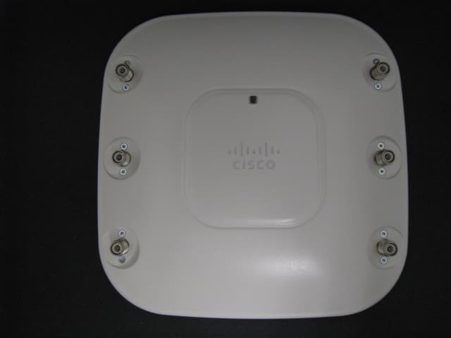
Click to zoom
Application Details
- Equipment Class
- DTS - Digital Transmission System
- Date of Grant
- Feb 08, 2012
- Application Purpose
- Original Equipment
- Date of Application
- Oct 27, 2011
- Equipment Note
- Cisco Aironet 802.11n Dual Band Access Points
- Frequency Range
- 5745.00000000 - 5805.00000000
- Company
- Cisco Systems Inc
- Country
- United States
Documents & Files
Document Text
Text extracted from the exhibit documents filed with the FCC. Open a document above to read the original.
Users Manual
GETTING STARTED GUIDE Cisco Aironet 3502P Lightweight Access Point 1About this Guide 2Safety Instructions 3Unpacking 4Overview 5Configuring the Access Point 6Mounting the Access Point 7Deploying the Access Point on the Wireless Network 8Troubleshooting 9Declarations of Conformity and Regulatory Information 10Configuring DHCP Option 43 and DHCP Option 60 11Access Point Specifications ap3502getstartForJMR3.fm Page 1 Thursday, October 27, 2011 11:28 AM 2 1 About this Guide This Guide provides instructions on how to install and configure your Cisco Aironet 3502P Access Point. This guide also provides mounting instructions and limited troubleshooting procedures. 2 Safety Instructions Translated versions of the following safety warnings are provided in the translated safety warnings document that is shipped with your access point. The translated warnings are also in the Translated Safety Warnings for Cisco Aironet Access Points, which is available on Cisco.com. WarningIMPORTANT SAFETY INSTRUCTIONS This warning symbol means danger. You are in a situation that could cause bodily injury. Before you work on any equipment, be aware of the hazards involved with electrical circuitry and be familiar with standard practices for preventing accidents. Use the statement number provided at the end of each warning to locate its translation in the translated safety warnings that accompanied this device. Statement 1071 SAVE THESE INSTRUCTIONS WarningOnly trained and qualified personnel should be allowed to install, replace, or service this equipment. Statement 1030 WarningIn order to comply with radio frequency (RF) exposure limits, the antennas for this product should be positioned no less than 6.56 ft (2 m) from your body or nearby persons. Statement 339 WarningRead the installation instructions before you connect the system to its power source. Statement 1004 WarningThis product must be connected to a Power-over-Ethernet (PoE) IEEE 802.3af compliant power source or an IEC60950 compliant limited power source. Statement 353 ap3502getstartForJMR3.fm Page 2 Thursday, October 27, 2011 11:28 AM 3 WarningInstallation of the equipment must comply with local and national electrical codes. Statement 1074 WarningThis product relies on the building’s installation for short-circuit (overcurrent) protection. Ensure that the protective device is rated not greater than: 20A. Statement 1005 WarningDo not operate your wireless network device near unshielded blasting caps or in an explosive environment unless the device has been modified to be especially qualified for such use. Statement 245B CautionThe fasteners you use to mount an access point on a ceiling must be capable of maintaining a minimum pullout force of 20 lbs (9 kg) and must use all 4 indented holes on the mounting bracket. CautionThis product and all interconnected equipment must be installed indoors within the same building, including the associated LAN connections as defined by Environment A of the IEEE 802.af Standard. NoteThe access point is suitable for use in environmental air space in accordance with section 300.22.C of the National Electrical Code and sections 2-128, 12-010(3), and 12-100 of the Canadian Electrical Code, Part 1, C22.1. You should not install the power supply or power injector in air handling spaces. NoteUse only with listed ITE equipment. ap3502getstartForJMR3.fm Page 3 Thursday, October 27, 2011 11:28 AM 4 3 Unpacking Follow these steps: Step 1Unpack and remove the access point and the accessory kit from the shipping box. Step 2Return any packing material to the shipping container and save it for future use. Step 3Verify that you have received the items listed below. If any item is missing or damaged, contact your Cisco representative or reseller for instructions. –3502P access point –Mounting bracket (selected when you ordered the access point) –Adjustable ceiling-rail clip (selected when you ordered the access point) ap3502getstartForJMR3.fm Page 4 Thursday, October 27, 2011 11:28 AM 5 4 Overview The following illustrations show the access point connections and features. Figure 1Access Point Ports and Connections (top) 1 2.4-GHz antenna connector B (labelled with black text) 4 5-GHz antenna connector A (labelled with blue text) 2 2.4-GHz antenna connector C (labelled with black text) 5 5-GHz antenna connector C (labelled with blue text) 3 2.4-GHz antenna connector A (labelled with black text) 6 5-GHz antenna connector B (labelled with blue text) 207613 52 3 1 6 4 ap3502getstartForJMR3.fm Page 5 Thursday, October 27, 2011 11:28 AM 6 Figure 2Access Point Ports and Connections (bottom) 1 Kensington lock slot 4 Console port 2 Power connection 5 Security padlock and hasp (padlock not included) 3 Ethernet port 6 Mounting bracket pins (feet for desk or table-top mount) 272377 234 15 66 ap3502getstartForJMR3.fm Page 6 Thursday, October 27, 2011 11:28 AM 7 5 Configuring the Access Point This section describes how to connect the access point to a wireless LAN controller. Because the configuration process takes place on the controller, see the Cisco Wireless LAN Controller Configuration Guide for additional information. This guide is available on Cisco.com. The Controller Discovery Process The 3502P access point uses the IETF standard Control and Provisioning of Wireless Access Points Protocol (CAPWAP) to communicate between the controller and other wireless access points on the network. CAPWAP is a standard, interoperable protocol which enables an access controller to manage a collection of wireless termination points. The discovery process using CAPWAP is identical to the Lightweight Access Point Protocol (LWAPP) used with previous Cisco Aironet access points. LWAPP-enabled access points are compatible with CAPWAP and conversion to a CAPWAP controller is seamless. Deployments can combine CAPWAP and LWAPP software on the controllers. The functionality provided by the controller does not change except for customers who have Layer 2 deployments,…
Text truncated - open the document above for the full version.
Cover Letter(s)
Jim Nicholson EMC Compliance Engineer Cisco Systems, Inc. 4125 Highlander Parkway Richfield, OH 44286 Phone: (330) 523-2094 Fax: (330) 523-2002 E-Mail: [email protected] July 28, 2011 Compliance Certification Services Certification Division 47173 Benicia Street Fremont, CA 94538, USA To whom it may concern: I, the undersigned, hereby authorize Ms. Claire Hoque/Application Examiner of Compliance Engineering Services, Inc., d.b.a. Compliance Certification Services and hereafter referred to as CCS, to act on our behalf in all manners relating to application for equipment authorization, including signing of all documents relating to these matters. Any and all acts carried out by Ms. Claire Hoque of CCS on our behalf shall have the same effect as acts of our own. I, the undersigned, hereby certify that we are not subject to a denial of federal benefits, that includes FCC benefits, pursuant to Section 5301 of the Anti-Drug Abuse Act of 1988, 21 U.S.C. 853(a). In authorizing CCS as our agent, we still recognize that we are responsible to: a) comply with the relevant provisions of the certification program; b) make all necessary arrangements for the conduct of the evaluation, including provision for examining documentation and access to all areas, records (including internal audit reports) and personnel for the purposes of evaluation (e.g. testing, inspection, assessment, surveillance, reassessment) and resolution of complaints; c) make claims regarding certification only in respect of the scope for which certification has been granted; d) do not use our product certification in such a manner as to bring the Certification Division into disrepute and not make any statement regarding our product certification which the Certification Division may consider misleading or unauthorized; e) upon suspension or cancellation of certification, discontinue use of all advertising matter that contains any reference thereto and return any certification documents as required by the Certification Division; f) use certification only to indicate the products are certified as being in conformity with specified standards; Jim Nicholson EMC Compliance Engineer Cisco Systems, Inc. 4125 Highlander Parkway Richfield, OH 44286 Phone: (330) 523-2094 Fax: (330) 523-2002 E-Mail: [email protected] g) endeavor to ensure that no certificate or report nor any part thereof is used in a misleading manner; h) ensure that any reference to our product certification in communication media such as documents, brochures or advertising, complies with the requirements of the Certification Division; i) keep a record of all complaints made known to the us relating to the product’s compliance with requirements of the relevant standard and to make these records available to the Certification Division when requested; j) take appropriate action with respect to such complaints and any deficiencies found in products or services that affect compliance with the requirements for certification; k) document the actions taken. This authorization is valid until further written notice from the applicant. Best Regards, Jim Nicholson EMC Compliance Engineer
Cover Letter(s)
Cisco Systems, Inc. 4125 Highlander Parkway Richfield, Ohio 44286 Phone: 330 523-2094 Fax: 330 523-2002 http://www.cisco.com Phone: (330) 523-2094 Fax: (330) 523-2002 E-Mail: [email protected] October 26, 2011 Federal Communications Commission Equipment Authorization Division, Application Processing Branch 7435 Oakland Mills Road Columbia, MD 21046 Re: FCC ID: LDK102079P To Whom It May Concern: The following information is to be held confidential pursuant to 47 CFR Part 0 §0.457 and Section 552(b)(4) of the Freedom of Information Act, because the information provided is proprietary and contains trade secrets. If made public, the information might be used to the disadvantage of the Cisco Systems, Inc. in the market place. Block Diagram Schematic Diagrams Hardware Theory of Operation Software Theory of Operation Best Regards, Jim Nicholson EMC Compliance Engineer
Cover Letter(s)
Jim Nicholson EMC Compliance Engineer Cisco Systems, Inc. 4125 Highlander Parkway Richfield, OH 44286 Phone: (330) 523-2094 Fax: (330) 523-2002 E-Mail: [email protected] October 26, 2011 Re: FCC ID: LDK102079P Applicant: Cisco Systems Inc Please apply the “DFS Expedited Review process” for this device based on the following criteria: Expedited Review Checklist Previous FCC ID: LDK102073 New Application FCC ID: LDK102079P Technology: 802.11n / MIMO 802.11n / MIMO Test labs used by this and previous report Cisco Systems Cisco Systems Differences between the products such as TX power, modulation, receivers, processing circuitry, etc. Supports 2 Tx /3 Rx paths, 17dBm Tx power per path Supports 2 Tx /3 Rx paths, 17dBm Tx power per path Differences / similarities in DFS functioning, circuitry, software, etc. Uses Marvel chipset and Cisco Systems "Clean Air" algorithm for DFS radar detection. DFS detection is controlled completely by the Cisco SaGE engine (the Cisco IP pulse processing and detection engine) embedded in the Marvel chip. Uses Marvel chipset and Cisco Systems "Clean Air" algorithm for DFS radar detection. DFS detection is controlled completely by the Cisco SaGE engine (the Cisco IP pulse processing and detection engine) embedded in the Marvel chip. Antenna information and differences for the minimum gain antennas Supports 2‐6 dBi antennas Supports 2‐7 dBi antennas Bandwidth information and differences Supports 20 and 40 MHz bandwidths Supports 20 and 40 MHz bandwidths Best Regards, Jim Nicholson Compliance Engineer
External Photos
3502 Series External Photos Top View Bottom View
ID Label/Location Info
3502 Series External Photos Top View Bottom View
Internal Photos
AP3502 Series Internal Photos
Test Report
Custom EMC Test Report No: EDCS - 895817 Page No: 1 of 166 This document is uncontrolled. Please refer to the electronic copy within EDCS for the most up to date version. Cisco Systems, Inc. Company Confidential Test Report AIR-CAP3502P-A-K9 Cisco Aironet 802.11n Single Band Access Points FCC ID: LDK102079P IC: 2461B-102079P (Also covers FCC ID: LDK102073P, IC: 2461B-102073P) 2400-2483.5 MHz Against the following Specifications: CFR47 Part 15.247 RSS210 Cisco Systems 170 West Tasman Drive San Jose, CA 95134 Custom EMC Test Report No: EDCS - 895817 Page No: 2 of 166 This document is uncontrolled. Please refer to the electronic copy within EDCS for the most up to date version. Cisco Systems, Inc. Company Confidential This test report has been electronically authorized and archived using the CISCO Engineering Document Control system. SECTION 1: OVERVIEW ......................................................................................................................................... 3 1.1 TEST SUMMARY ...................................................................................................................................................... 3 SECTION 2: ASSESSMENT INFORMATION ...................................................................................................... 4 2.1 GENERAL ................................................................................................................................................................. 4 2.4 TESTING FACILITIES ............................................................................................................................................... 5 2.6 EUT DESCRIPTION .................................................................................................................................................. 5 SECTION 4: SAMPLE DETAILS ............................................................................................................................. 7 APPENDIX A: EMISSION TEST RESULTS .................................................................................................. 8 AVERAGE OUTPUT POWER ........................................................................................................................................... 8 6DB BANDWIDTH ........................................................................................................................................................... 9 99% AND 26DB BANDWIDTH ....................................................................................................................................... 21 PEAK OUTPUT POWER ................................................................................................................................................ 33 POWER SPECTRAL DENSITY ....................................................................................................................................... 46 CONDUCTED SPURIOUS EMISSIONS ........................................................................................................................... 58 APPENDIX B: EMISSION TEST RESULTS ................................................................................................ 71 RADIATED BANDEDGE .................................................................................................................................................. 71 RADIATED SPURIOUS EMISSIONS ................................................................................................................................ 129 2.4GHZ 5.2DBI OMNICONDUCTED EMISSIONS ........................................................................................................... 160 CONDUCTED EMISSIONS ............................................................................................................................................. 160 RADIATED EMISSIONS ................................................................................................................................................. 162 MAXIMUM PERMISSIBLE EXPOSURE (MPE) CALCULATIONS ................................................................................... 164 APPENDIX C: TEST EQUIPMENT/SOFTWARE USED TO PERFORM THE TEST ............................. 166 Custom EMC Test Report No: EDCS - 895817 Page No: 3 of 166 This document is uncontrolled. Please refer to the electronic copy within EDCS for the most up to date version. Cisco Systems, Inc. Company Confidential Section 1: Overview 1.1 Test Summary samples were assessed against the tests detailed in section 3 under the requirements of the following specifications: Emission Immunity CFR47 Part 15.247 RSS210 N/A The specifications listed above represent actual tests performed to demonstrate compliance against the specifications and basic standards listed on the front cover of this report. This list is not a one to one match to the front cover for one or more of the following reasons. 1. Basic standards call up many different test phenomena specifications such as the 61000-4-X series. The basic standards define which elements and levels shall be applied from these specifications and as such it is not appropriate to list the individual specifications on the front cover. 2. A Standard listed on the front cover may be required in a particular country but is not appropriate for the particular technologies included in the equipment under test. E.g. You cannot test a DC product to the mains Harmonics requirements in EN61000-3-2. See section 3.2. 3. Test results against a particular standard or specification may be included in a different test report. See section 3.2 for an EDCS reference of this data. 4. Where appropriate, Cisco may have substituted a later revision of a basic standard to those referenced in the specification on the front sheet of this test report. This decision was based upon improved test methodology and repeatability and/or where the newer revision represented a more stringent test. 5.…
Text truncated - open the document above for the full version.
Test Report
Custom EMC Test Report No: EDCS - 895816 Page No: 1 of 54 This document is uncontrolled. Please refer to the electronic copy within EDCS for the most up to date version. Cisco Systems, Inc. Company Confidential Test Report AIR-CAP3502P-A-K9 Cisco Aironet 802.11n Dual Band Access Points FCC ID: LDK102079P IC: 2461B-102079P (Also covers FCC ID: LDK102073P, IC: 2461B-102073P) (Also covers AIR-CAP3502P-N-K9, AIR-CAP3502P-T-K9) 5725-5850 MHz Against the following Specifications: CFR47 Part 15.247 RSS210 Cisco Systems 170 West Tasman Drive San Jose, CA 95134 Custom EMC Test Report No: EDCS - 895816 Page No: 2 of 54 This document is uncontrolled. Please refer to the electronic copy within EDCS for the most up to date version. Cisco Systems, Inc. Company Confidential This test report has been electronically authorized and archived using the CISCO Engineering Document Control system. SECTION 1: OVERVIEW ......................................................................................................................................... 3 1.1 TEST SUMMARY ...................................................................................................................................................... 3 SECTION 2: ASSESSMENT INFORMATION ...................................................................................................... 4 2.1 GENERAL ................................................................................................................................................................. 4 2.4 TESTING FACILITIES ............................................................................................................................................... 5 2.6 EUT DESCRIPTION .................................................................................................................................................. 5 SECTION 4: SAMPLE DETAILS ............................................................................................................................. 6 APPENDIX A: EMISSION TEST RESULTS .................................................................................................. 8 AVERAGE OUTPUT POWER ........................................................................................................................................... 8 6DB BANDWIDTH ........................................................................................................................................................... 9 99% AND 26DB BANDWIDTH ....................................................................................................................................... 14 PEAK OUTPUT POWER ................................................................................................................................................ 19 POWER SPECTRAL DENSITY ....................................................................................................................................... 24 CONDUCTED SPURIOUS EMISSIONS ........................................................................................................................... 29 APPENDIX B: EMISSION TEST RESULTS ................................................................................................ 35 RADIATED BANDEDGE .................................................................................................................................................. 35 RADIATED SPURIOUS EMISSIONS .................................................................................................................................. 40 MAXIMUM PERMISSIBLE EXPOSURE (MPE) CALCULATIONS ..................................................................................... 52 APPENDIX C: TEST EQUIPMENT/SOFTWARE USED TO PERFORM THE TEST ............................... 54 Custom EMC Test Report No: EDCS - 895816 Page No: 3 of 54 This document is uncontrolled. Please refer to the electronic copy within EDCS for the most up to date version. Cisco Systems, Inc. Company Confidential Section 1: Overview 1.1 Test Summary samples were assessed against the tests detailed in section 3 under the requirements of the following specifications: Emission Immunity CFR47 Part 15.247 RSS210 N/A The specifications listed above represent actual tests performed to demonstrate compliance against the specifications and basic standards listed on the front cover of this report. This list is not a one to one match to the front cover for one or more of the following reasons. 1. Basic standards call up many different test phenomena specifications such as the 61000-4-X series. The basic standards define which elements and levels shall be applied from these specifications and as such it is not appropriate to list the individual specifications on the front cover. 2. A Standard listed on the front cover may be required in a particular country but is not appropriate for the particular technologies included in the equipment under test. E.g. You cannot test a DC product to the mains Harmonics requirements in EN61000-3-2. See section 3.2. 3. Test results against a particular standard or specification may be included in a different test report. See section 3.2 for an EDCS reference of this data. 4. Where appropriate, Cisco may have substituted a later revision of a basic standard to those referenced in the specification on the front sheet of this test report. This decision was based upon improved test methodology and repeatability and/or where the newer revision represented a more stringent test. 5. Where relevant, testing has been carried out to the requirements of both EN and IEC Specifications. This was possible because of the similarities of the test methods involved and the Cisco EMC test procedures. 6. Testing may have been performed to an equivalent test that satisfies the requirements of the standards and specifications listed on the front cover of the report. See section 3.2. 7. Where radiated emissions testing has been…
Text truncated - open the document above for the full version.
Test Setup Photos
Applicant: Cisco Systems, Inc. FCC ID: LDK102079P For Setup Photos of LDK102079P, please see Cisco DTS and NII reports.
Contact Information
Applicant
Samuel Kim(Manager, Engineering)
Technical Contact
Compliance Certification Services (UL CCS)Claire Hoque
[email protected](510) 771-1000
47173 Benicia Street · Fremont, California · United States
Test Firm
Compliance Certification ServicesThu Chan
Technical Specifications
| # | Rule Parts | Frequency Range | Power Output |
|---|---|---|---|
| 3 | 15C | 5.75 GHz - 5.80 GHz | 117.50 mW |
Other Applications from Cisco Systems Inc

LDKJ98213058
May 25, 2026Wireless Phone
Equipment Class
DSS - Part 15 Spread Spectrum TransmitterLDKIW9165E
Aug 20, 2024Wi-Fi 6E Outdoor Access Point
Equipment Class
6SD - 15E 6 GHz Standard Power Access PointLDKIW9165DH
Aug 05, 2024Wi-Fi 6E Outdoor Access Point
Equipment Class
6SD - 15E 6 GHz Standard Power Access PointLDKUSBC2857
Jul 22, 2024Cisco Headset USB-C Adapter
Equipment Class
DSS - Part 15 Spread Spectrum TransmitterLDKESPRD2922
May 09, 2024UC Phone
Equipment Class
NII - Unlicensed National Information Infrastructure TX