LDK102091Cisco Aironet 2700 Series Access Points
Cisco Systems Inc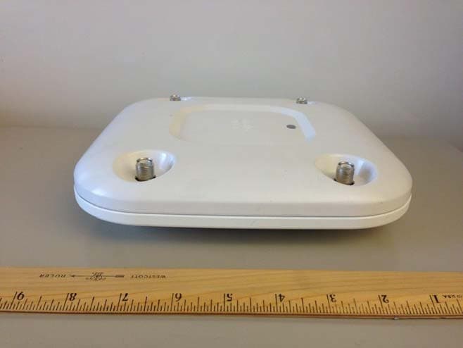
Click to zoom
Application Details
- Equipment Class
- DTS - Digital Transmission System
- Date of Grant
- Dec 15, 2013
- Application Purpose
- Original Equipment
- Date of Application
- Nov 24, 2013
- Equipment Note
- Cisco Aironet 2700 Series Access Points
- Frequency Range
- 5745.00000000 - 5825.00000000
- Company
- Cisco Systems Inc
- Country
- United States
Documents & Files
Document Text
Text extracted from the exhibit documents filed with the FCC. Open a document above to read the original.
Users Manual
GETTING STARTED GUIDE Cisco Aironet 2700 Series Access Points 1About this Guide 2Introduction to the Access Point 3Safety Instructions 4Unpacking 5Configurations 6Access Point Ports and Connectors 7Configuring the Access Point 8Mounting the Access Point 9Deploying the Access Point on the Wireless Network 10Installing Modules 10Troubleshooting 11Declarations of Conformity and Regulatory Information 12Configuring DHCP Option 43 and DHCP Option 60 13Access Point Specifications 2 Revised: 1 About this Guide This Guide provides instructions on how to install and configure your Cisco Aironet 2700 Series Access Point. This guide also provides mounting instructions and limited troubleshooting procedures. The 2700 Series Access Point is referred to as the access point in this document. 2 Introduction to the Access Point The 2700 series supports high-performing Spectrum Intelligence which sustains three spatial stream rates over a deployable distance with high reliability when serving clients. The 2700 series provides high reliability and overall wireless performance. The 2700 series offers dual-band radios (2.4 GHz and 5 GHz) with integrated and external antenna options. The access points support full inter-operability with leading 802.11ac clients, and support a mixed deployment with other access points and controllers. The 2700 series access point is a controller-based (Unified) product and supports: •Simultaneous dual-band (2.4-GHz and 5-GHz) radios •Integrated antennas on the 2702I access point model (AIR-CAP2702I-x-K9) •External antennas for rugged 2702E access point model (AIR-CAP2702E-x-K9) NoteThe ‘x’ in the model numbers represents the regulatory domain. Refer to “Regulatory Domains” section on page 6 for a list of supported regulatory domains. The features of the 2700 series are: •Processing sub-systems (including CPUs and memory) and radio hardware which supports: –Network management –CleanAir—Automatic detection, classification, location and mitigation of RF interference –ClientLink+—BeamForming to 802.11n clients as well as legacy 802.11a/g OFDM clients –VideoStream –Location –WIDS/WIPS –Security –Radio Resource Management (RRM) 3 –Rogue detection –Management Frame Protection (MFP) –Throughput, forwarding, and filtering performance scaled to meet 3 spatial stream, 1.3-Gbps data-rates •32 MB flash size •802.11af/at –CDP (Cisco Discovery Protocol) •2.4 GHz and 5 GHz 802.11n radios with the following features: –4TX x 4RX –3-spatial streams, 1.3-Gbps PHY rate –Spectrum intelligence –DPD (Digital Pre-Distortion) technology –Cisco Vector Beamforming—Implicit Co-phase beamforming for .11ag clients and 1x1 11n clients –Radio hardware is capable of explicit compressed beamforming (ECBF) per 802.11n standard 3 Safety Instructions Translated versions of the following safety warnings are provided in the translated safety warnings document that is shipped with your access point. The translated warnings are also in the Translated Safety Warnings for Cisco Aironet Access Points, which is available on Cisco.com. WarningIMPORTANT SAFETY INSTRUCTIONS This warning symbol means danger. You are in a situation that could cause bodily injury. Before you work on any equipment, be aware of the hazards involved with electrical circuitry and be familiar with standard practices for preventing accidents. Use the statement number provided at the end of each warning to locate its translation in the translated safety warnings that accompanied this device. Statement 1071 SAVE THESE INSTRUCTIONS WarningRead the installation instructions before you connect the system to its power source. Statement 1004 4 WarningInstallation of the equipment must comply with local and national electrical codes. Statement 1074 WarningThis product relies on the building’s installation for short-circuit (overcurrent) protection. Ensure that the protective device is rated not greater than: 20A. Statement 1005 WarningDo not operate your wireless network device near unshielded blasting caps or in an explosive environment unless the device has been modified to be especially qualified for such use. Statement 245B WarningIn order to comply with FCC radio frequency (RF) exposure limits, antennas should be located at a minimum of 7.9 inches (20 cm) or more from the body of all persons. Statement 332 CautionThe fasteners you use to mount an access point on a ceiling must be capable of maintaining a minimum pullout force of 20 lbs (9 kg) and must use all 4 indented holes on the mounting bracket. CautionThis product and all interconnected equipment must be installed indoors within the same building, including the associated LAN connections as defined by Environment A of the IEEE 802.af Standard. NoteThe access point is suitable for use in environmental air space in accordance with section 300.22.C of the National Electrical Code and sections 2-128, 12-010(3), and 12-100 of the Canadian Electrical Code, Part 1, C22.1. You should not install the power supply or power injector in air handling spaces. NoteUse only with listed ITE equipment. 5 4 Unpacking To unpack the access point, follow these steps: Step 1Unpack and remove the access point and the accessory kit from the shipping box. Step 2Return any packing material to the shipping container and save it for future use. Step 3Verify that you have received the items listed below. If any item is missing or damaged, contact your Cisco representative or reseller for instructions. –The access point –Mounting bracket (selected when you ordered the access point) –Adjustable ceiling-rail clip (selected when you ordered the access point) 5 Configurations The 2700 series access point contains two simultaneous dual-band radios, the 2.4-GHz MIMO radio and the 5-GHz 802.11ac MIMO radio. The 2700 series access point configurations are: •AIR-CAP2702E-x-K9—two 2.4-GHz/5-GHz dual-band radios, up to 4 external dual-band diopole antennas •AIR-CAP2702I-x-K9—two 2.4-GHz/5-GHz dual-band radios, with integrated du…
Text truncated - open the document above for the full version.
Cover Letter(s)
EDCS-1216337 12/04/2012 Subject : Authorized signatures The following people are authorized by Cisco Systems to sign documents for FCC product approval under FCC Grantee code LDK on behalf of the company. Further this right is extended to any regular Cisco employee as deemed necessary. David A, Case Jim Nicholson Trinh Tien Donn Foster Bruce Touzel Howard Ji Phil Carranco Jose Aguirre Collin Wilson Lisa Bevington Andy Griffin Mark King Dave Wilson Allan Beecroft Bob Lyall Pushpinder Sawanni Julius “ Bud” Chiller Chuck Troia Francois Caron Steve Granzella Regards Kenny Wee Cisco Systems
Cover Letter(s)
November 21, 2013 Federal Communications Commission Equipment Authorization branch 7435 Oakland Mills Road Columbia, MD 21046 To Whom It May Concern: In reference to the application under FCC ID: LDK102091 and pursuant to Sections 0.457(d)(l)(ii) and 0.459 of the Commission’s Rules, the Applicant hereby requests confidential treatment of the accompanying information as outlined below: Schematics Block Diagram Radio Theory of Operation Series Software Theory of Operation These documents contain detailed system and equipment description and related information about the product that Cisco considers to be proprietary, confidential, and a custom design and, otherwise, would not release to the general public. Since this design is a basis from which future technological products will evolve, Cisco considers that this information would be of benefit to its competitors, and that disclosure of the information in these documents would give competitors an unfair advantage in the market. Best Regards, Jim Nicholson EMC Compliance Engineer 4125 Highlander Parkway Richfield, Ohio 44286 Email: [email protected] Direct: (330)523-2094
Cover Letter(s)
Jim Nicholson EMC Compliance Engineer Cisco Systems, Inc. 4125 Highlander Parkway Richfield, OH 44286 Phone: (330) 523-2094 Fax: (330) 523-2002 E-Mail: [email protected] November 25, 2013 Re: FCC ID: LDK102091 Applicant: Cisco Systems Inc Date of Original E-mail: 11/25/2013 Please apply the “DFS Expedited Review process” for this device based on the following criteria: Expedited Review Checklist Previous FCC ID: LDK102087 New Application FCC ID: LDK102091 Technology: 802.11n / ac 802.11n / ac Test labs used by this and previous report Cisco Systems Cisco Systems Differences between the products such as TX power, modulation, receivers, processing circuitry, etc. Supports 4 Tx /4 Rx paths, 17dBm Tx power per path Supports 4 Tx / 4 Rx paths, 17dBm Tx power per path. Differences / similarities in DFS functioning, circuitry, software, etc. Uses Marvel chipset and Cisco Systems "Clean Air" algorithm for DFS radar detection. DFS detection is controlled completely by the Cisco SaGE engine (the Cisco IP pulse processing and detection engine) embedded in the Marvel chip. Uses Marvel chipset and Cisco Systems "Clean Air" algorithm for DFS radar detection. DFS detection is controlled completely by the Cisco SaGE engine (the Cisco IP pulse processing and detection engine) embedded in the Marvel chip. This engine is identical to the SaGE engine used in LDK102087 Antenna information and differences for the minimum gain antennas Supports 2‐6 dBi antennas Supports 2‐6 dBi antennas Bandwidth information and differences Supports 20, 40 and 80MHz bandwidths Supports 20,40 and 80MHz bandwidths Best Regards, Jim Nicholson Compliance Engineer
Cover Letter(s)
2700 Label Location
External Photos
2700E External Photos Top view Bottom View Side 1 view Side 2 view Side 3 view Side 4 view
External Photos
2700I External Photos Top view Bottom View Side 1 view Side 2 view Side 3 view Side 4 view
ID Label/Location Info
2700 Label Location
Internal Photos
2700 Series Internal Assembly Antennas Board Top Board Bottom Unshielded Board Top Unshielded Board Bottom
RF Exposure Info
Custom EMC Test Report No: EDCS -1325273 Page No: 328 of 330 This document is uncontrolled. Please refer to the electronic copy within EDCS for the most up to date version. Cisco Systems, Inc. Company Confidential Maximum Permissible Exposure (MPE) Calculations 15.247: U-NII devices are subject to the radio frequency radiation exposure requirements specified in Sec. 1.1307(b), Sec. 2.1091 and Sec. 2.1093 of this chapter, as appropriate. All equipment shall be considered to operate in a ``general population/uncontrolled'' environment. Applications for equipment authorization of devices operating under this section must contain a statement confirming compliance with these requirements for both fundamental emissions and unwanted emissions. Technical information showing the basis for this statement must be submitted to the Commission upon request. Given E=√(30*P*G)/d and S=E^2/3770 where E=Field Strength in Volts/meter P=Power in Watts G=Numeric Antenna Gain d=Distance in meters S=Power Density in mW/cm^2 Combine equations and rearrange the terms to express the distance as a function of the remaining variables: d=√((30*P*G)/(3770*S)) Changing to units of power in mW and distance in cm, using: P(mW)=P(W)/1000 d(cm)=100*d(m) yields d=100*√((30*(P/1000)*G)/(3770*S)) d=0.282*√(P*G/S) where d=Distance in cm P=Power in mW G=Numerica Antenna Gain S=Power Density in mW/cm^2 Substituting the logarithmic form of power and gain using: P(mW)=10^(P(dBm)/10) G(numeric)=10^(G(dBi)/10) yields d=0.282*10^((P+G)/20)/√S Equation (1) and s=((0.282*10^((P+G)/20))/d)^2 Equation (2) where d=MPE distance in cm P=Power in dBm G=Antenna Gain in dBi S=Power Density in mW/cm^2 Custom EMC Test Report No: EDCS -1325273 Page No: 329 of 330 This document is uncontrolled. Please refer to the electronic copy within EDCS for the most up to date version. Cisco Systems, Inc. Company Confidential Equation (1) and the measured peak power are used to calculate the MPE distance. Note that for mobile or fixed location transmitters such as an access point, the minimum separation distance is 20 cm even if the calculations indicate that the MPE distance may be less. S=1mW/cm^2 maximum. The highest supported antenna gain is 6 dBi (9dBi with beamforming). Using the peak power levels recorded in the test report along with Equation 1 above, the MPE distances are calculated as follows. MPE Calculations: Frequency (MHz) Power Density (mW/cm^2) Peak Transmit Power (dBm) Antenna Gain (dBi) MPE Distance (cm) Limit (cm) Margin (cm) 2412 1 21.4 6 6.61 20 13.39 2462 1 21.4 6 6.61 20 13.39 To maintain compliance, installations will assure a separation distance of at least 20cm. Using Equation 2, the MPE levels (s) at 20 cm are calculated as follows: Frequency (MHz) MPE Distance (cm) Peak Transmit Power (dBm) Antenna Gain (dBi) Power Density (mW/cm^2) Limit (mW/cm^2) Margin (mW/cm^2) 2412 20 21.4 6 0.11 1 0.89 2462 20 21.4 6 0.11 1 0.89
RF Exposure Info
Custom EMC Test Report No: EDCS - 1325625 Page No: 527 of 529 This document is uncontrolled. Please refer to the electronic copy within EDCS for the most up to date version. Cisco Systems, Inc. Company Confidential Maximum Permissible Exposure (MPE) Calculations 15.247: U-NII devices are subject to the radio frequency radiation exposure requirements specified in Sec. 1.1307(b), Sec. 2.1091 and Sec. 2.1093 of this chapter, as appropriate. All equipment shall be considered to operate in a ``general population/uncontrolled'' environment. Applications for equipment authorization of devices operating under this section must contain a statement confirming compliance with these requirements for both fundamental emissions and unwanted emissions. Technical information showing the basis for this statement must be submitted to the Commission upon request. Given E=√(30*P*G)/d and S=E^2/3770 where E=Field Strength in Volts/meter P=Power in Watts G=Numeric Antenna Gain d=Distance in meters S=Power Density in mW/cm^2 Combine equations and rearrange the terms to express the distance as a function of the remaining variables: d=√((30*P*G)/(3770*S)) Changing to units of power in mW and distance in cm, using: P(mW)=P(W)/1000 d(cm)=100*d(m) yields d=100*√((30*(P/1000)*G)/(3770*S)) d=0.282*√(P*G/S) where d=Distance in cm P=Power in mW G=Numeric Antenna Gain S=Power Density in mW/cm^2 Substituting the logarithmic form of power and gain using: P(mW)=10^(P(dBm)/10) G(numeric)=10^(G(dBi)/10) yields d=0.282*10^((P+G)/20)/√S Equation (1) and s=((0.282*10^((P+G)/20))/d)^2 Equation (2) where d=MPE distance in cm P=Power in dBm G=Antenna Gain in dBi S=Power Density in mW/cm^2 Custom EMC Test Report No: EDCS - 1325625 Page No: 528 of 529 This document is uncontrolled. Please refer to the electronic copy within EDCS for the most up to date version. Cisco Systems, Inc. Company Confidential Equation (1) and the measured peak power are used to calculate the MPE distance. Note that for mobile or fixed location transmitters such as an access point, the minimum separation distance is 20 cm even if the calculations indicate that the MPE distance may be less. S=1mW/cm^2 maximum. The highest supported antenna gain is 6 dBi (9dBi with beamforming). Using the peak power levels recorded in the test report along with Equation 1 above, the MPE distances are calculated as follows. MPE Calculations: Frequency (Mhz) Power Density (mW/cm^2) Peak Transmit Power (dBm) Antenna Gain (dBi) MPE Distance (cm) Limit (cm) Margin (cm) 5745 1 22 6 7.17 20 12.83 5785 1 22 6 6.87 20 13.13 5795 1 23 6 7.52 20 12.48 5825 1 21 6 6.44 20 13.56 To maintain compliance, installations will assure a separation distance of at least 20cm. Using Equation 2, the MPE levels (s) at 20 cm are calculated as follows: Frequency (Mhz) MPE Distance (cm) Peak Transmit Power (dBm) Antenna Gain (dBi) Power Density (mW/cm^2) Limit (mW/cm^2) Margin (mW/cm^2) 5745 20 22 6 0.13 1 0.87 5785 20 22 6 0.12 1 0.88 5795 20 23 6 0.14 1 0.86 5825 20 21 6 0.10 1 0.90
Test Report
Custom EMC Test Report No: EDCS -1325273 Page No: 1 of 330 This document is uncontrolled. Please refer to the electronic copy within EDCS for the most up to date version. Cisco Systems, Inc. Company Confidential Test Report AIR-CAP2702E-A-K9 FCC ID: LDK102091 IC: 2461B-102091 Also Covers: AIR-CAP2702y-D-K9 AIR-CAP2702y-N-K9 AIR-CAP2702y-T-K9 AIR-CAP2702y-Z-K9 y = E (External Antenna) or I (Internal Antenna) 2400-2483.5 MHz Against the following Specifications: CFR47 Part 15.247 RSS210 Cisco Systems 170 West Tasman Drive San Jose, CA 95134 Test Engineer: _____________________ Custom EMC Test Report No: EDCS -1325273 Page No: 2 of 330 This document is uncontrolled. Please refer to the electronic copy within EDCS for the most up to date version. Cisco Systems, Inc. Company Confidential This test report has been electronically authorized and archived using the CISCO Engineering Document Control system. SECTION 1: OVERVIEW ......................................................................................................................................... 3 1.1 TEST SUMMARY ................................................................................................................................................... 3 SECTION 2: ASSESSMENT INFORMATION ...................................................................................................... 4 2.1 GENERAL ............................................................................................................................................................. 4 2.2 DATE OF TESTING ................................................................................................................................................ 5 2.3 REPORT ISSUE DATE ............................................................................................................................................ 5 2.4 TESTING FACILITIES ............................................................................................................................................. 5 2.5 EQUIPMENT ASSESSED (EUT) ............................................................................................................................. 5 2.6 EUT DESCRIPTION ............................................................................................................................................... 6 SECTION 4: SAMPLE DETAILS ............................................................................................................................. 7 APPENDIX A: EMISSION TEST RESULTS ................................................................................................... 8 TARGET MAXIMUM CHANNEL POWER ...................................................................................................................... 8 6DB BANDWIDTH ...................................................................................................................................................... 9 99% AND 26DB BANDWIDTH .................................................................................................................................. 16 PEAK OUTPUT POWER ........................................................................................................................................... 23 POWER SPECTRAL DENSITY .................................................................................................................................. 89 CONDUCTED SPURIOUS EMISSIONS ...................................................................................................................... 96 CONDUCTED BANDEDGE ...................................................................................................................................... 101 APPENDIX B: EMISSION TEST RESULTS ............................................................................................... 317 RADIATED SPURIOUS EMISSIONS ........................................................................................................................ 317 RADIATED EMISSIONS ........................................................................................................................................... 326 MAXIMUM PERMISSIBLE EXPOSURE (MPE) CALCULATIONS ................................................................................. 328 APPENDIX C: TEST EQUIPMENT/SOFTWARE USED TO PERFORM THE TEST ............................. 329 Custom EMC Test Report No: EDCS -1325273 Page No: 3 of 330 This document is uncontrolled. Please refer to the electronic copy within EDCS for the most up to date version. Cisco Systems, Inc. Company Confidential Section 1: Overview 1.1 Test Summary The samples were assessed against the tests detailed in section 3 under the requirements of the following specifications: Emission Immunity CFR47 Part 15.247 RSS210 N/A The specifications listed above represent actual tests performed to demonstrate compliance against the specifications and basic standards listed on the front cover of this report. This list is not a one to one match to the front cover for one or more of the following reasons. 1. Basic standards call up many different test phenomena specifications such as the 61000-4-X series. The basic standards define which elements and levels shall be applied from these specifications and as such it is not appropriate to list the individual specifications on the front cover. 2. A Standard listed on the front cover may be required in a particular country but is not appropriate for the particular technologies included in the equipment under test. E.g. You cannot test a DC product to the mains Harmonics requirements in EN61000-3-2. See section 3.2. 3. Test results against a particular standard or specification may be included in a different test report. See section 3.2 for an EDCS reference of this data. 4. Where appropriate, Cisco may have substituted a later revision of a basic standard to those referenced in the specification on the fron…
Text truncated - open the document above for the full version.
Test Report
Custom EMC Test Report No: EDCS - 1325625 Page No: 1 of 529 This document is uncontrolled. Please refer to the electronic copy within EDCS for the most up to date version. Cisco Systems, Inc. Company Confidential Test Report AIR-CAP2702y-A-K9 FCC ID: LDK102091 IC: 2461B-102091 Also Covers: AIR-CAP2702y-T-K9 AIR-CAP2702y-N-K9 AIR-CAP2702y-Z-K9 y =E (External Antenna) or I (Internal Antenna) 5725-5850 MHz Against the following Specifications: CFR47 Part 15.247 RSS210 Cisco Systems 170 West Tasman Drive San Jose, CA 95134 Test Engineer: _____________________ Custom EMC Test Report No: EDCS - 1325625 Page No: 2 of 529 This document is uncontrolled. Please refer to the electronic copy within EDCS for the most up to date version. Cisco Systems, Inc. Company Confidential This test report has been electronically authorized and archived using the CISCO Engineering Document Control system. SECTION 1: OVERVIEW ......................................................................................................................................... 3 1.1 TEST SUMMARY.................................................................................................................................................. 3 SECTION 2: ASSESSMENT INFORMATION ...................................................................................................... 4 2.1 GENERAL ............................................................................................................................................................ 4 2.2 DATE OF TESTING ............................................................................................................................................... 5 08-OCTOBER-2013 .................................................................................................................................................... 5 2.3 REPORT ISSUE DATE .......................................................................................................................................... 5 2.4 TESTING FACILITIES ........................................................................................................................................... 5 TRINH TIEN ............................................................................................................................................................... 5 2.5 EQUIPMENT ASSESSED (EUT) ........................................................................................................................... 5 2.6 EUT DESCRIPTION ............................................................................................................................................. 6 APPENDIX A: EMISSION TEST RESULTS ................................................................................................... 8 TARGET MAXIMUM CHANNEL POWER ...................................................................................................................... 8 6DB BANDWIDTH 9 99% AND 26DB BANDWIDTH .................................................................................................................................. 17 PEAK OUTPUT POWER ........................................................................................................................................... 25 POWER SPECTRAL DENSITY ................................................................................................................................ 184 CONDUCTED SPURIOUS EMISSION ...................................................................................................................... 192 APPENDIX B: EMISSION TEST RESULTS ............................................................................................... 518 RADIATED SPURIOUS EMISSIONS ........................................................................................................................ 518 RADIATED EMISSIONS ........................................................................................................................................... 525 MAXIMUM PERMISSIBLE EXPOSURE (MPE) CALCULATIONS............................................................................... 527 APPENDIX C: TEST EQUIPMENT/SOFTWARE USED TO PERFORM THE TEST ............................. 529 Custom EMC Test Report No: EDCS - 1325625 Page No: 3 of 529 This document is uncontrolled. Please refer to the electronic copy within EDCS for the most up to date version. Cisco Systems, Inc. Company Confidential Section 1: Overview 1.1 Test Summary The samples were assessed against the tests detailed in section 3 under the requirements of the following specifications: Emission Immunity CFR47 Part 15.247 RSS210 N/A The specifications listed above represent actual tests performed to demonstrate compliance against the specifications and basic standards listed on the front cover of this report. This list is not a one to one match to the front cover for one or more of the following reasons. 1. Basic standards call up many different test phenomena specifications such as the 61000-4-X series. The basic standards define which elements and levels shall be applied from these specifications and as such it is not appropriate to list the individual specifications on the front cover. 2. A Standard listed on the front cover may be required in a particular country but is not appropriate for the particular technologies included in the equipment under test. E.g. You cannot test a DC product to the mains Harmonics requirements in EN61000-3-2. See section 3.2. 3. Test results against a particular standard or specification may be included in a different test report. See section 3.2 for an EDCS reference of this data. 4. Where appropriate, Cisco may have substituted a later revision of a basic standard to those referenced in the specification on the front sheet of this test report. This decision was based upon improved test methodology and repeatability and/or where the newer revision represented a more stri…
Text truncated - open the document above for the full version.
Test Report
Cond Ante Ant e Custom E This d o ducted Spurs enna A enna C EMC Test Rep ocument is unco rs Average, 5 port No: EDC ontrolled. Pleas C 5785 MHz, HT S - 1325625 Page se refer to the isco Systems, T/VHT20 Bea No: 301 of 52 electronic cop y Inc. Company am Forming, Antenna B Antenna D 9 y within EDCS Confidential M8 to M15, M B D for the most u M0.2 to M9.2 p to date versio 2 on. Cond Ante Ant e Custom E This d o ducted Spurs enna A enna C EMC Test Rep ocument is unco rs Average, 5 port No: EDC ontrolled. Pleas C 5785 MHz, HT S - 1325625 Page se refer to the isco Systems, T/VHT20 Bea No: 302 of 52 electronic cop y Inc. Company am Forming, Antenna B Antenna D 9 y within EDCS Confidential M16 to M23, B D for the most u M0.3 to M9. p to date versio 3 on. Cond Ante Custom E This d o ducted Spurs enna A EMC Test Rep ocument is unco rs Average, 5 port No: EDC ontrolled. Pleas C 5785 MHz, HT S - 1325625 Page se refer to the isco Systems, T/VHT20 STB No: 303 of 52 electronic cop y Inc. Company BC, M0 to M7 Antenna B 9 y within EDCS Confidential 7, M0.1 to M9 B for the most u 9.1 p to date versioon. Cond Ante Ant e Custom E This d o ducted Spurs enna A enna C EMC Test Rep ocument is unco rs Average, 5 port No: EDC ontrolled. Pleas C 5785 MHz, HT S - 1325625 Page se refer to the isco Systems, T/VHT20 STB No: 304 of 52 electronic cop y Inc. Company BC, M0 to M7 Antenna B 9 y within EDCS Confidential 7, M0.1 to M9 B for the most u 9.1 p to date versioon. Cond Ante Ant e Custom E This d o ducted Spurs enna A enna C EMC Test Rep ocument is unco rs Average, 5 port No: EDC ontrolled. Pleas C 5785 MHz, HT S - 1325625 Page se refer to the isco Systems, T/VHT20 STB No: 305 of 52 electronic cop y Inc. Company BC, M0 to M7 Antenna B Antenna D 9 y within EDCS Confidential 7, M0.1 to M9 B D for the most u 9.1 p to date versio on. Cond Ante Custom E This d o ducted Spurs enna A EMC Test Rep ocument is unco rs Average, 5 port No: EDC ontrolled. Pleas C 5795 MHz, No S - 1325625 Page se refer to the isco Systems, on HT/VHT40 No: 306 of 52 electronic cop y Inc. Company 0, 6 to 54 Mbp 9 y within EDCS Confidential ps for the most up to date versioon. Cond Ante Custom E This d o ducted Spurs enna A EMC Test Rep ocument is unco rs Average, 5 port No: EDC ontrolled. Pleas C 5795 MHz, No S - 1325625 Page se refer to the isco Systems, on HT/VHT40…
Text truncated - open the document above for the full version.
Contact Information
Applicant
Samuel Kim(Manager, Engineering)
Technical Contact
Cisco Systems IncJim Nicholson
[email protected]216-849-7241
4125 Highlander Parkway · Richfield, Ohio · United States
Test Firm
Cisco Systems, Inc.Dave Wilson
Technical Specifications
| # | Rule Parts | Frequency Range | Power Output |
|---|---|---|---|
| 2 | 15C | 5.75 GHz - 5.83 GHz | 178.00 mW |
Other Applications from Cisco Systems Inc

LDKJ98213058
May 25, 2026Wireless Phone
Equipment Class
DSS - Part 15 Spread Spectrum TransmitterLDKIW9165E
Aug 20, 2024Wi-Fi 6E Outdoor Access Point
Equipment Class
6SD - 15E 6 GHz Standard Power Access PointLDKIW9165DH
Aug 05, 2024Wi-Fi 6E Outdoor Access Point
Equipment Class
6SD - 15E 6 GHz Standard Power Access PointLDKUSBC2857
Jul 22, 2024Cisco Headset USB-C Adapter
Equipment Class
DSS - Part 15 Spread Spectrum TransmitterLDKESPRD2922
May 09, 2024UC Phone
Equipment Class
NII - Unlicensed National Information Infrastructure TX