LDK102093P1572 Series Cisco Aironet 802.11ac Dual Band Access Points
Cisco Systems Inc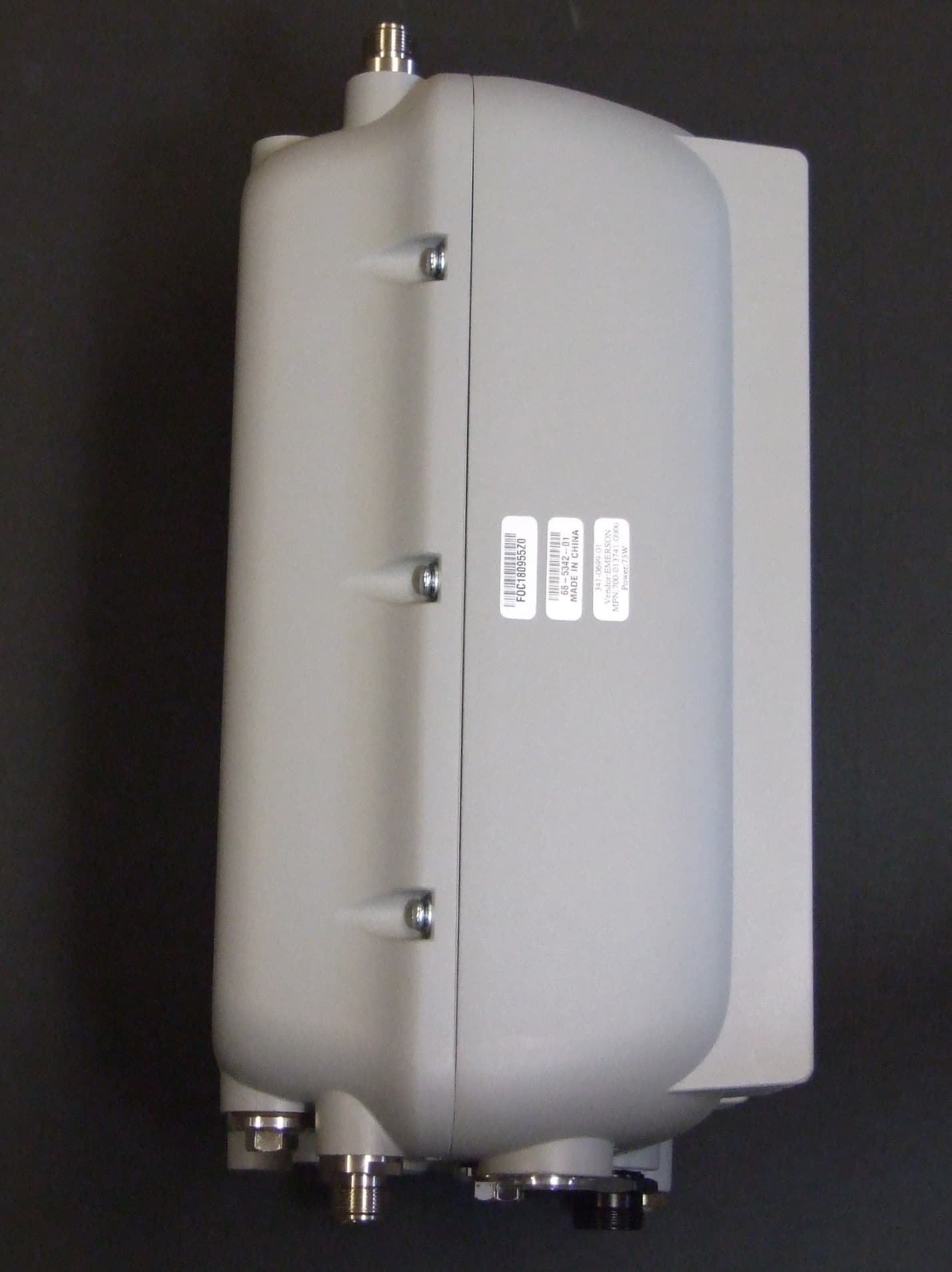
Click to zoom
Application Details
- Equipment Class
- NII - Unlicensed National Information Infrastructure TX
- Date of Grant
- Jan 14, 2015
- Application Purpose
- Original Equipment
- Date of Application
- Jan 11, 2015
- Equipment Note
- 1572 Series Cisco Aironet 802.11ac Dual Band Access Points
- Frequency Range
- 5660.00000000 - 5720.00000000
- Company
- Cisco Systems Inc
- Country
- United States
Documents & Files
Select a file to view
Document Text
Text extracted from the exhibit documents filed with the FCC. Open a document above to read the original.
Users Manual
© 2014 Cisco and/or its affiliates. All rights reserved. This document is Cisco Confidential. - DRAFT Page 1 of 10 PRELIMINARY Data Sheet Next-Generation Outdoor Wireless ● Dual-band 2.4 and 5 GHz with 802.11ac Wave 1 support on the integrated 5-GHz radio ● Cisco ® CleanAir ™ technology provides integrated spectrum intelligence for a self-configuring and self-healing network ● ClientLink improves reliability and coverage for legacy clients ● Improved 802.11ac range and performance with 4x4:3 multiple-input multiple-output (MIMO) technology ● 1.3 Gbps data rates ● Multiple-radio support (802.11b/g/n, 802.11a/n/ac) ● DOCSIS 3.0/EuroDOCSIS/JapanDOCSIS 3.0, 16x8 hybrid fiber-coaxial (HFC) cable modem option ● Improved radio sensitivity and range performance with four antenna MIMO and three spatial streams ● Multiple uplink options (Gigabit Ethernet- 10/100/1000 BaseT, Fiber SFP, interface-cable (certain models) ● NEMA Type 4X certified enclosure Cisco Aironet 1572IC ● Internal Antennas with Cable modem model Cisco Aironet 1572EC ● Cable modem model with External Antennas Cisco Aironet 1572EAC ● External antenna model Cisco Aironet 1570 Series Outdoor Access Point High-Performance Outdoor Wireless The Cisco ® Aironet ® 1570 Series Outdoor Access Point with Cisco CleanAir ™ technology is the industry’s first enterprise and carrier-grade 802.11ac access point to create a self-healing and self- optimizing wireless network that mitigates the impact of wireless interference. It offers a flexible, secure, and scalable mesh network for high-performance mobility across large metropolitan-sized areas, enterprise campuses, manufacturing yards, and mining pits. The Cisco Aironet 1570 Series supports multiple-device and multiple-network application delivery such as real-time seamless mobility, video surveillance, 3 rd Generation (3G) and 4G data offload, and public and private Wi-Fi access. Designed to meet customer needs in a broad range of industries, the Cisco Aironet 1570 Series offers the following benefits: ● Flexible deployment options: Access or mesh network, extension of an Ethernet network, and Ethernet, fiber, wireless, or cable backhaul. ● Service provider support: Wi-Fi for next-generation mobile data offload and personalized mobile services. ● Cisco CleanAir technology: Integrated spectrum intelligence to detect, classify, and mitigate RF interference from unauthorized wireless bridges or malicious devices. ● High-bandwidth video surveillance over Wi-Fi without the high cost of installing cables over long distances. ● High-performance, multipurpose network with low CapEx and OpEx. ● Integrated wired and wireless: The Cisco Borderless Network Architecture provides cost savings with end-to-end network access solutions that include wireless, switching, routing, and security. © 2014 Cisco and/or its affiliates. All rights reserved. This document is Cisco Public Information. - DRAFT Page 2 of 10 Flexible, High-Performance Mesh The Cisco Aironet 1570 Series Outdoor Access Point offers a flexible, secure, and scalable mesh platform that is part of the Cisco Unified Wireless Network and the Cisco Service Provider Wi-Fi solution. It offers high- performance mobility across large metropolitan-sized areas and enterprise campuses, manufacturing yards, and mining pits. Carrier-grade design allows service providers to take advantage of Wi-Fi for next-generation mobile data offloads. The Cisco Aironet 1570 Series provides high-performance device access through improved radio sensitivity and range with 802.11a/b/g/n/ac multiple-input multiple-output (MIMO) technology, with three spatial streams. Multiple uplink and power options are available. The 802.3at-compliant, Power-over-Ethernet (PoE) interface makes it easy to connect IP devices, such as IP video cameras. NEMA Type 4X enclosures help ensure a robust system that can withstand demanding environments. The external antenna models include the option to attach an external module to the Access Point and power off the 802.3at from that AP. Cisco CleanAir Technology The Cisco Aironet 1570 Series with Cisco CleanAir technology provides the highest-performance 802.11ac connectivity for mission-critical outdoor networks by detecting interference from unauthorized devices, as well as common outdoor interference sources, such as WiMAX networks and wireless bridging products. The 1570 Series uses chip-level intelligence to create a spectrum-aware, self-healing, and self-optimizing wireless network that mitigates the impact of wireless interference. Cisco CleanAir technology is a systemwide feature of the Cisco Unified Wireless Network that improves wireless network quality by detecting RF interference that other systems can’t recognize, identifying the source, locating it, and then making automatic adjustments to optimize wireless coverage. RF Excellence Building on the Cisco Aironet heritage of RF excellence, the Cisco Aironet 1570 Series delivers industry-leading performance for secure and reliable wireless connections. Industrial-grade parts, enterprise-class silicon-level intelligence, and optimized radios deliver a robust mobility experience. The Cisco Aironet 1570 Series provides a set of tools that deliver the robust, scalable wireless foundation required to realize the true potential of outdoor wireless mobility: ● Cisco ClientLink technology to raise uplink and downlink performance of and coverage to 802.11a/g/n/ac clients ● Radio resource management (RRM) for automated channel selection and power setting management of access points ● Advanced capabilities to select data rates, adjust power, and manage quality of service (QoS) for access points © 2014 Cisco and/or its affiliates. All rights reserved. This document is Cisco Public Information. - DRAFT Page 3 of 10 Centrally Managed Mesh Network Central management and troubleshooting of the Cisco outdoor wireless access points prevent costly maintenance service calls to outdoor locations. The Cisco Prime I…
Text truncated - open the document above for the full version.
Users Manual
Data Sheet © 2011 Cisco and/or its affiliates. All rights reserved. This document is Cisco Public Information. Page 1 of 4 New FCC Guidelines for Installation and Operation of Outdoor Wireless LAN devices (“U-NII devices”) Operating in the 5470-5725- MHz Band. The following Federal Communications Commission (FCC) guidelines required for operation of WLAN systems were created to help mitigate interference to Federal Aviation Administration (FAA) Terminal Doppler Weather Radar (TDWR) from Wireless LAN systems operating outdoors in the 5470-5725-MHz band. The FAA has reported interference to many of their radar systems from WLANs operating specifically in the 5600-5650-MHz TDWR band, as well as from operation of WLANs on adjacent channels. The FCC, FAA, and National Telecommunications and Information Administration (NTIA) have been investigating the issues, and have reported to industry that the cases of interference stem from many different causes. In addition to temporarily stopping new equipment certification for outdoor devices, the FCC has asked the industry to help address the issue by applying these guidelines to customer installations and ensuring customers are aware of the guidelines and how to comply. Note: These installation and operation guidelines apply to new systems being installed outdoors as well as current systems already installed and operating. Requirements The following requirements for installation and operation of outdoor systems must be addressed: 1. Operation in the 5600-5650-MHz band is not authorized for 5-GHz WLAN systems, whether operating indoor or outdoors. This does not pose a problem for Cisco ® WLAN since this band is not accessible for Cisco products. Use of indoor-only equipment outdoors can lead to FCC enforcement action, such as fines or requirements to disable the system. This includes installations where the access point is placed indoors and the antenna is placed outdoors, as well as installations involving retractable roofs (for example, football stadiums). 2. For WLAN systems being installed outdoors, the following requirements must be met. a) Systems must be professionally installed by a qualified engineer familiar with WLAN, including Cisco trained partners and resellers. b) Operation in the 5600-5650-MHz band is prohibited. c) It is recommended that the installer register the installation of their system in the Wireless Internet Service Providers Association (WISPA database). This is especially important for systems that are installed within 35 km of the FAA TDWR. (Please see the links later in this document to WISPA database with TDWR locations.) d) When within 35 km distance of a TDWR, the center frequency of the WLAN must be separated from the TDWR center frequency by 30 MHz. a. If the radar is operating from 5600-5610 MHz, disable the use of channel 116 (5580 MHz). b. If the radar is operating from 5630-5650 MHz, disable the use of channel 132 (5660 MHz). Note: Cisco will be disabling channels 116 and 132 for outdoor systems in the future, the instructions in (d) only applies to systems that currently have the channels enabled. Data Sheet © 2011 Cisco and/or its affiliates. All rights reserved. This document is Cisco Public Information. Page 2 of 4 e) Additional mitigation techniques can include first, not orienting the antennas in the main beam of the weather radar, and second, ensuring that the antenna is not positioned in line-of-sight of the FAA TDWR. f) Verify that the antennas used are approved for use with Cisco WLAN systems. Installers or operators using nonapproved antennas or making any unauthorized changes may be subject to enforcement action. WISPA Database In conjunction with industry, the Wireless Internet Service Providers Association (WISPA) has created a database for installers and operators for registration of these outdoor systems including Mesh installations. This database, accessible from the WISPA website http://www.spectrumbridge.com/udrs/home.aspx, should be used by the installer or operator to determine if they are within 35 km of the TDWR, as well as to register the system if operating within this range of the TDWR. This will help the FCC and FAA address interference issues in the future. Cisco strongly urges our customers to register their outdoor systems in this database: Instructions for WISPA Database Registration 1. Connect to the database at: http://www.spectrumbridge.com/udrs/home.aspx. This will take you to the main page. 2. On the main page, select Search at the upper-left. This will take you to the TDWR radar page. Enter the requested information to find the proximity of specific WLAN systems to TDWR systems. 3. If you need to register one or more WLANs, you will need an account. Click the User Signup button on the page and create a registration for your company. There is no charge for registration. 4. Once you are registered user or if already registered log in using your username and password. 5. Select “device management” - to start process to register your device. 6. Enter all information and follow procedure as instructed to complete registration. Once you complete your registration for that device, you can repeat the process for other devices needing to be registered. Table 1 shows the TDWR information provided by NTIA, this information is here to use as a quick reference, please see WISPA web page for any changes or additions. Table 1. TDWR Location Information STATE CITY LONGITUDE LATITUDE FREQUENCY TERRAIN ELEVATION (MSL) [ft] ANTENNA HEIGHT ABOVE TERRAIN [ft] AZ PHOENIX W 112 09 46 N 33 25 14 5610 MHz 1024 64 CO DENVER W 104 31 35 N 39 43 39 5615 MHz 5643 64 FL FT LAUDERDALE W 080 20 39 N 26 08 36 5645 MHz 7 113 FL MIAMI W 080 29 28 N 25 45 27 5605 MHz 10 113 FL ORLANDO W 081 19 33 N 28 20 37 5640 MHz 72 97 FL TAMPA W 082 31 04 N 27 51 35 5620 MHz 14 80 FL WEST PALM BEACH W 080 16 23 N 26 41 17 5615 MHz 20 113 GA ATLANTA W 084 15 44 N 33 38 48 5615 MHz 962 113 IL MCCOOK W 087 51 31 N 41 47 50 561…
Text truncated - open the document above for the full version.
Users Manual
Cisco Systems, Inc. www.cisco.com Cisco has more than 200 offices worldwide. Addresses, phone numbers, and fax numbers are listed on the Cisco website at www.cisco.com/go/offices. Cisco Aironet 1570 Series Outdoor Access Point Hardware Installation Guide October, 2014 Text Part Number: OL-32138-01 THE SPECIFICATIONS AND INFORMATION REGARDING THE PRODUCTS IN THIS MANUAL ARE SUBJECT TO CHANGE WITHOUT NOTICE. ALL STATEMENTS, INFORMATION, AND RECOMMENDATIONS IN THIS MANUAL ARE BELIEVED TO BE ACCURATE BUT ARE PRESENTED WITHOUT WARRANTY OF ANY KIND, EXPRESS OR IMPLIED. USERS MUST TAKE FULL RESPONSIBILITY FOR THEIR APPLICATION OF ANY PRODUCTS. THE SOFTWARE LICENSE AND LIMITED WARRANTY FOR THE ACCOMPANYING PRODUCT ARE SET FORTH IN THE INFORMATION PACKET THAT SHIPPED WITH THE PRODUCT AND ARE INCORPORATED HEREIN BY THIS REFERENCE. IF YOU ARE UNABLE TO LOCATE THE SOFTWARE LICENSE OR LIMITED WARRANTY, CONTACT YOUR CISCO REPRESENTATIVE FOR A COPY. The following information is for FCC compliance of Class A devices: This equipment has been tested and found to comply with the limits for a Class A digital device, pursuant to part 15 of the FCC rules. These limits are designed to provide reasonable protection against harmful interference when the equipment is operated in a commercial environment. This equipment generates, uses, and can radiate radio-frequency energy and, if not installed and used in accordance with the instruction manual, may cause harmful interference to radio communications. Operation of this equipment in a residential area is likely to cause harmful interference, in which case users will be required to correct the interference at their own expense. The following information is for FCC compliance of Class B devices: This equipment has been tested and found to comply with the limits for a Class B digital device, pursuant to part 15 of the FCC rules. These limits are designed to provide reasonable protection against harmful interference in a residential installation. This equipment generates, uses and can radiate radio frequency energy and, if not installed and used in accordance with the instructions, may cause harmful interference to radio communications. However, there is no guarantee that interference will not occur in a particular installation. If the equipment causes interference to radio or television reception, which can be determined by turning the equipment off and on, users are encouraged to try to correct the interference by using one or more of the following measures: •Reorient or relocate the receiving antenna. •Increase the separation between the equipment and receiver. •Connect the equipment into an outlet on a circuit different from that to which the receiver is connected. •Consult the dealer or an experienced radio/TV technician for help. Modifications to this product not authorized by Cisco could void the FCC approval and negate your authority to operate the product. The Cisco implementation of TCP header compression is an adaptation of a program developed by the University of California, Berkeley (UCB) as part of UCB’s public domain version of the UNIX operating system. All rights reserved. Copyright © 1981, Regents of the University of California. NOTWITHSTANDING ANY OTHER WARRANTY HEREIN, ALL DOCUMENT FILES AND SOFTWARE OF THESE SUPPLIERS ARE PROVIDED “AS IS” WITH ALL FAULTS. CISCO AND THE ABOVE-NAMED SUPPLIERS DISCLAIM ALL WARRANTIES, EXPRESSED OR IMPLIED, INCLUDING, WITHOUT LIMITATION, THOSE OF MERCHANTABILITY, FITNESS FOR A PARTICULAR PURPOSE AND NONINFRINGEMENT OR ARISING FROM A COURSE OF DEALING, USAGE, OR TRADE PRACTICE. IN NO EVENT SHALL CISCO OR ITS SUPPLIERS BE LIABLE FOR ANY INDIRECT, SPECIAL, CONSEQUENTIAL, OR INCIDENTAL DAMAGES, INCLUDING, WITHOUT LIMITATION, LOST PROFITS OR LOSS OR DAMAGE TO DATA ARISING OUT OF THE USE OR INABILITY TO USE THIS MANUAL, EVEN IF CISCO OR ITS SUPPLIERS HAVE BEEN ADVISED OF THE POSSIBILITY OF SUCH DAMAGES. Cisco and the Cisco logo are trademarks or registered trademarks of Cisco and/or its affiliates in the U.S. and other countries. To view a list of Cisco trademarks, go to this URL: www.cisco.com/go/trademarks. Third-party trademarks mentioned are the property of their respective owners. The use of the word partner does not imply a partnership relationship between Cisco and any other company. (1110R) Any Internet Protocol (IP) addresses and phone numbers used in this document are not intended to be actual addresses and phone numbers. Any examples, command display output, network topology diagrams, and other figures included in the document are shown for illustrative purposes only. Any use of actual IP addresses or phone numbers in illustrative content is unintentional and coincidental. © 2014 Cisco Systems, Inc. All rights reserved. iii Cisco Aironet 1570 Series Outdoor Access Point Hardware Installation Guide OL-32138-01 CONTENTS Prefacevii Objectivesvii Audiencevii Organizationviii Conventionsviii Related Documentsxiv Finding the Product Serial Numberxv Obtaining Documentation, Support, and Security Guidelinesxvi CHAPTER 1Overview1-1 About the Access Point1-1 Hardware Models and Supported Regulatory Domains1-2 Features of the Access Point1-3 Processing Subsystem and Storage1-3 Operating Modes1-3 Antennas1-4 AIR-AP1572I Internal Antennas1-4 AIR-AP1572E External Antennas1-4 Non-Cisco Antennas1-4 Antenna Configurations1-5 Radios1-5 Power Sources1-6 Power-over-Cable1-7 AC Power Supply1-8 DC Interface1-8 PoE-Input1-8 Optional Hardware1-8 Network Deployment Examples1-10 Wireless Backhaul1-10 Point-to-Point Bridging1-10 Point-to-Multipoint Bridging1-11 Point-to-Multipoint Mesh Network1-13 Contents iv Cisco Aironet 1570 Series Outdoor Access Point Hardware Installation Guide OL-32138-01 Layer 3 Network Operation1-14 CHAPTER 2Installing the Access Point2-1 Unpacking the Access Point2-2 Package Contents2-2 Tools and Hardware2-2 Optional Tools and Hardware2-2 Optional Tools and Hardware That You Supply2-3 Warnings2-3 Safety Informati…
Text truncated - open the document above for the full version.
Cover Letter(s)
EDCS-1216337 07/09/2014 Subject : Authorized signatures The following people are authorized by Cisco Systems to sign documents for FCC product approval under FCC Grantee code LDK on behalf of the company. Further this right is extended to any regular Cisco employee as deemed necessary. David A, Case Jim Nicholson Trinh Tien Donn Foster Howard Ji Jose Aguirre Colin Wilson Lisa Bevington Andy Griffin Mark King Dave Wilson Allan Beecroft Bob Lyall Pushpinder Sawanni Julius “ Bud” Chiller Chuck Troia Steve Granzella Rekha Simha Regards Gerard Thorpe Cisco Systems
External Photos
AIR‐AP1572xxx‐B‐K9 Series Exterior Pictures July 25, 2014 FCC I.D. LDK102093P External Antenna Models AIR-AP1572EAC-B-K9 AIR-AP1572ECx-B-K9 (x designates cable modem variant not effecting radio operation) Internal Antenna Model AIR-AP1572ICx-B-K9 (x designates cable modem variant not effecting radio operation)
ID Label/Location Info
AIR‐AP1572xxx‐B‐K9 Series Label July 25, 2014 FCC I.D. LDK102093P Label Artwork Label Location
Internal Photos
AIR‐AP1572xxx‐B‐K9 Series Internal Assembly Pictures July 25, 2014 FCC I.D. LDK102093P External Antenna Models AIR-AP1572EAC-B-K9 Control (red) and Radio Board AC Power Supply Power Over Ethernet Supply Board AIR-AP1572ECx-B-K9 (x designates cable modem variant not effecting radio operation) Control, Radio and PoE Supply Board PoE Supply and internal divider Internal Antenna Model AIR-AP1572ICx-B-K9 (x designates cable modem variant not effecting radio operation) Internal Antenna Assembly Antennas, Radio (left) and Control Boards Radio, Control and Cable Connector Center Panel Under Assembly Power Over Cable Supply (left) and Cable Modem Board
Test Report
Custom EMC Test Report No: EDCS - Page No: 1 of 20 This document is uncontrolled. Please refer to the electronic copy within EDCS for the most up to date version. Cisco Systems, Inc. Company Confidential Test Report Spurious Emissions AIR-AP1572xxx-x-K9 FCC ID: LDK102093P IC: 2461B-102093P 5.150 – 5.850 MHz Against the following Specifications: CFR47 Part 15 Cisco Systems 170 West Tasman Drive San Jose, CA 95134 Engineer: Date: 11-3-2014 Custom EMC Test Report No: EDCS - Page No: 2 of 20 This document is uncontrolled. Please refer to the electronic copy within EDCS for the most up to date version. Cisco Systems, Inc. Company Confidential This test report has been electronically authorized and archived using the CISCO Engineering Document Control system. SECTION 1: OVERVIEW ......................................................................................................................................... 3 1.1 TEST SUMMARY.................................................................................................................................................. 3 SECTION 2: ASSESSMENT INFORMATION ...................................................................................................... 4 2.1 GENERAL ............................................................................................................................................................ 4 2.2 DATE OF TESTING ............................................................................................................................................... 5 2.3 REPORT ISSUE DATE .......................................................................................................................................... 5 2.4 TESTING FACILITIES ........................................................................................................................................... 5 2.5 EQUIPMENT ASSESSED (EUT) ........................................................................................................................... 5 2.6 EUT DESCRIPTION ............................................................................................................................................. 5 APPENDIX A: EMISSION TEST RESULTS ................................................................................................... 6 APPENDIX B: Test Equipment/Software Used to perform the test ..........................................20 Custom EMC Test Report No: EDCS - Page No: 3 of 20 This document is uncontrolled. Please refer to the electronic copy within EDCS for the most up to date version. Cisco Systems, Inc. Company Confidential Section 1: Overview 1.1 Test Summary The samples were assessed against the tests detailed in section 3 under the requirements of the following specifications: Emission Immunity CFR47 Part 15 N/A The specifications listed above represent actual tests performed to demonstrate compliance against the specifications and basic standards listed on the front cover of this report. This list is not a one to one match to the front cover for one or more of the following reasons. 1. Basic standards call up many different test phenomena specifications such as the 61000-4-X series. The basic standards define which elements and levels shall be applied from these specifications and as such it is not appropriate to list the individual specifications on the front cover. 2. A Standard listed on the front cover may be required in a particular country but is not appropriate for the particular technologies included in the equipment under test. E.g. You cannot test a DC product to the mains Harmonics requirements in EN61000-3-2. See section 3.2. 3. Test results against a particular standard or specification may be included in a different test report. See section 3.2 for an EDCS reference of this data. 4. Where appropriate, Cisco may have substituted a later revision of a basic standard to those referenced in the specification on the front sheet of this test report. This decision was based upon improved test methodology and repeatability and/or where the newer revision represented a more stringent test. 5. Where relevant, testing has been carried out to the requirements of both EN and IEC Specifications. This was possible because of the similarities of the test methods involved and the Cisco EMC test procedures. 6. Testing may have been performed to an equivalent test that satisfies the requirements of the standards and specifications listed on the front cover of the report. See section 3.2. 7. Where radiated emissions testing has been performed to EN55022/CISPR22 the additional requirements of VCCI: V- 3/2006.04, EN55022: 1994 +A1/2 and CAN/CSA- CISPR 22-02 have also been evaluated unless otherwise stated. 8. Testing to the requirements of CFR47 Part 15 was performed against the CISPR22 limits. The results are therefore deemed satisfactory evidence of compliance with Industry Canada Interference Causing Equipment Standard ICES-003. 9. Where assessment has been performed to CISPR24, all the applicable test requirements may have not been covered. Refer to the results section for the tests performed. Notes: 1) Where a specification listed on the front cover of this report has deviations from the basic standards listed above, the additional technical requirements of the specification were also assessed. 2) Where appropriate, Cisco may have substituted a later revision of a basic standard to those referenced in the specification on the front sheet of this test report. This decision was based upon improved test methodology and repeatability and/or where the newer revision represented a more stringent test. 3) Where relevant, testing has been carried out to the requirements of both EN and IEC Specifications. This was possible because of the similarities of the test methods involved and the Cisco EMC test procedures. Custom EMC Test Report No: EDCS - Page No: 4 of 20 This document is uncontrolled. Please refer to…
Text truncated - open the document above for the full version.
Test Report
Custom Test Report No: EDCS - 1433005 Page No: 1 of 71 This document is uncontrolled. Please refer to the electronic copy within EDCS for the most up to date version. Cisco Systems, Inc. Company Confidential Dynamic Frequency Selection (DFS) Test Report AIR-AP1572xxx-B-K9 (Where x = model options not effecting the radio module) FCC ID: LDK102093P 5250-5350, 5470-5725 MHz Against the following Specifications: CFR47 Part 15.407 Cisco Systems 170 West Tasman Drive San Jose, CA 95134 Test Engineer: __________________ Date: _________________________ Custom EMC Test Report No: EDCS-1134841 Page No: 2 of 71 This document is uncontrolled. Please refer to the electronic copy within EDCS for the most up to date version. Cisco Systems, Inc. Company Confidential This test report has been electronically authorized and archived using the CISCO Engineering Document Control system. 1.0 UNII DEVICE DESCRIPTION .............................................................................................................. 3 2.0 DFS DETECTION THRESHOLDS ...................................................................................................... 5 3.0 RADAR TEST WAVEFORMS ............................................................................................................. 6 4.0 RADAR WAVEFORM CALIBRATION ................................................................................................ 9 5.0 TEST PROCEDURE/RESULTS ......................................................................................................... 13 UNII DETECTION BANDWIDTH RESULTS, 20MHZ SIGNAL BANDWIDTH ................................................................ 16 INITIAL CHANNEL AVAILABILITY CHECK TIME .......................................................................................................... 40 RADAR BURST AT THE BEGINNING OF THE CHANNEL AVAILABILITY CHECK TIME ................................................. 41 RADAR BURST AT THE END OF THE CHANNEL AVAILABILITY CHECK TIME ............................................................ 42 CHANNEL MOVE TIME, CHANNEL CLOSING TRANSMISSION TIME FOR USA BIN 1 ............................................... 44 30 MINUTE NON-OCCUPANCY PERIOD (USING TYPE 1 RADAR) ............................................................................ 47 USA BIN 1 RADAR STATISTICAL PERFORMANCE ................................................................................................... 49 USA BIN 2 RADAR STATISTICAL PERFORMANCE ................................................................................................... 50 USA BIN 3 RADAR STATISTICAL PERFORMANCE ................................................................................................... 51 USA BIN 4 RADAR STATISTICAL PERFORMANCE ................................................................................................... 52 Custom EMC Test Report No: EDCS-1134841 Page No: 3 of 71 This document is uncontrolled. Please refer to the electronic copy within EDCS for the most up to date version. Cisco Systems, Inc. Company Confidential Dynamic Frequency Selection (DFS) Test Results 15.407: U-NII devices operating in the 5.25-5.35 GHz band and the 5.47-5.725 GHz band shall employ a TPC mechanism. The U-NII device is required to have the capability to operate at least 6 dB below the mean EIRP value of 30 dBm. A TPC mechanism is not required for systems with an e.i.r.p. of less than 500 mW. U-NII devices operating in the 5.25-5.35 GHz and 5.47-5.725 GHz bands shall employ a DFS radar detection mechanism to detect the presence of radar systems and to avoid co-channel operation with radar systems. 1.0 UNII Device Description 1. The AIR-AP1572 Series Cisco Aironet 802.11ac Module operates in the following bands: a. 5250-5350 MHz b. 5470-5725 MHz (excluding 5600-5650 MHz) c. 5725-5850 MHz 2. The maximum EIRP of the 5GHz equipment is 43 dBm, and the minimum possible EIRP is 21 dBm. Below are the available 50 ohm antenna assemblies and their corresponding gains. 0dBi gain was used to set the -63 dBm threshold level (-64dBm +1 dB) during calibration of the test setup. Frequen cy Part Number Antenna Type Antenna Gain (2GHz/5GHz) (dBi) >30 degree 5 GHz Antenna Gain (d Bi) 5 GHz AIR-ANT5140V-N 5GHZ Omni 4 -2 AIR-ANT5180V-N 5GHZ Omni 8 -3 AIR-ANT5114P-N 5GHz Patch 14 -4 AIR-ANT5114P2M -N Patch…
Text truncated - open the document above for the full version.
Contact Information
Applicant
Samuel Kim(Manager, Engineering)
Test Firm
Cisco Systems, Inc.Dave Wilson
Technical Specifications
| # | Rule Parts | Frequency Range | Power Output |
|---|---|---|---|
| 4 | 15E | 5.66 GHz - 5.72 GHz | 178.00 mW |
Other Applications from Cisco Systems Inc

LDKJ98213058
May 25, 2026Wireless Phone
Equipment Class
DSS - Part 15 Spread Spectrum TransmitterLDKIW9165E
Aug 20, 2024Wi-Fi 6E Outdoor Access Point
Equipment Class
6SD - 15E 6 GHz Standard Power Access PointLDKIW9165DH
Aug 05, 2024Wi-Fi 6E Outdoor Access Point
Equipment Class
6SD - 15E 6 GHz Standard Power Access PointLDKUSBC2857
Jul 22, 2024Cisco Headset USB-C Adapter
Equipment Class
DSS - Part 15 Spread Spectrum TransmitterLDKESPRD2922
May 09, 2024UC Phone
Equipment Class
NII - Unlicensed National Information Infrastructure TX