LDK53100936Universal Small Cell Module 5310 3G Module
Cisco Systems Inc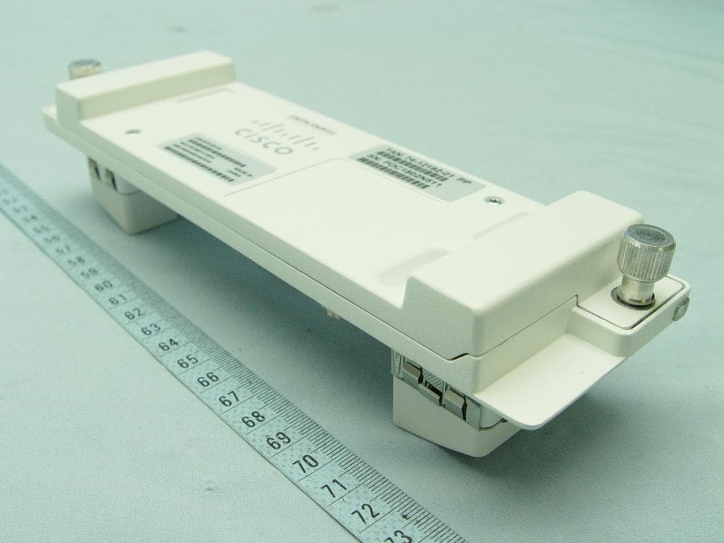
Click to zoom
Application Details
- Equipment Class
- PCB - PCS Licensed Transmitter
- Date of Grant
- Feb 13, 2014
- Application Purpose
- Original Equipment
- Date of Application
- Feb 13, 2014
- Equipment Note
- Universal Small Cell Module 5310 3G Module
- Frequency Range
- 1932.40000000 - 1987.60000000
- Company
- Cisco Systems Inc
- Country
- United States
Documents & Files
Document Text
Text extracted from the exhibit documents filed with the FCC. Open a document above to read the original.
Users Manual
QUICK START GUIDE Cisco Universal Small Cell 5310 3G Module 1Before You Begin 2Install Your USC 5310 Module 3Verify Your Installation 4Specifications 5Obtaining Documentation and Submitting a Service Request 2 Revised: November, 2013, 78-21438-02 1 Before You Begin A fully integrated, high-performance, low-cost third-generation (3G) small cell, your Universal Small Cell (USC) 5310 module is a licensed radio network extension that connects to the module port of the Cisco Aironet 3600 Series access point, which is a UL listed ITE product. This small cell module contains a dedicated 3G small cell base station that delivers mobile services indoors, while offloading traffic from the outdoor macro network. Using the standards-based technology of Home Node B (HNB), the USC 5310 module provides 3G signals inside a building for voice, data and messaging services for up to 16 simultaneous users within a coverage area of approximately 7000 square feet (650 square meters). The module supports Band 2/5 for the American market and Band 1 for the rest of the world. System Requirements This module is designed for use with Cisco Aironet 3600 Series access points. The module is not designed for use with other access points. The USC 5310 module is supported on these Cisco wireless LAN controllers: •Cisco 5500 Series Wireless Controller •Cisco 7500 Series Wireless Controller •Cisco 8500 Series Wireless Controller The USC 5310 is supported by the following software releases: •Cisco Unified Wireless Network Software Release 7.6 or later •Cisco Universal Small Cell Software Release 3.3 or later •Cisco Small Cell Solution Release 2.0 or later 3 Power Considerations Installation of your small cell module requires an additional 6 watts to power the Cisco Aironet 3600 access point. With a USC 5310 module installed, the access point requires the full Power over Ethernet Plus (PoE+) of 25.5 Watts at the egress switch port and a cable run of less than 300 feet (100 meters). Power options for the access point include: •IEEE 802.3at POE+ 25.5 W delivered from the upstream Ethernet switch •Cisco 3600 Series Power Injector (AIR-PWRINJ4=) •Cisco 3600 Series local power supply (AIR-PWR-B=) The USC 5310 module has a power limit circuitry that shuts down the module if it draws more power than allowed. Installation Considerations Install your small cell: •in a central location, in an area where people are most likely to make calls •away from windows, to avoid the signal leaking outside or external signals leaking in •in an open area with airflow; not in a closed cabinet which reduces the signal strength If you have thick internal walls, or metal, fire or rotating doors, plan to place units at either side of the obstruction at a distance shorter than 49 feet (15 m). Install a unit across from a corner to provide coverage on both sides of the corner. For more information, refer to the “Cisco Aironet AP Module for Wireless Security and Spectrum Intellgence (WSSI) Deployment Guide” at the following URL: http://www.cisco.com/en/US/products/ps11983/ products_tech_note09186a0080bed15d.shtml. 4 2 Install Your USC 5310 Module Follow these steps to install the USC 5310 module: Step 1Remove the module from the packaging. Step 2Power down the access point. Step 3Peel off the label from the back of the 3600 series access point to reveal the module port connector. Figure 1Backside of Cisco Aironet 3600 Access Point 1 Openings for module’s antennas 2 Label covering port connector 380755 1 21 5 Step 4Align the module connector with the connector on the back of the access point and click the module into place. Figure 2Installing Module in the Cisco Aironet 3600 Access Point Step 5Screw down the thumb screws on the module. NoteIf the screws are not tightened, the module will not be recognized and may not operate correctly. Make sure not to over-tighten the screws; they should be only hand-tightened. Step 6Power up the access point. When the access point boots up, it recognizes the module. No software configuration is required. Step 7If necessary, mount the Cisco Aironet 3600 Series access point, with the USC 5310 plug-in module installed, using the universal bracket (AIR-AP-BRACKET-2). 380756 6 NoteThe universal bracket works with electrical boxes, can be used for wall mounting, and adapts to ceiling installations. It leaves a larger gap between the mounting surface and the access point, which allows space for the USC 5310 plug-in module. For more information, refer to “Access Point Mounting Instructions” at the following URL: http://www.cisco.com/en/US/docs/ wireless/access_point/mounting/guide/apmount.html 3 Verify Your Installation After the USC 5310 module is installed in the access point and powered up, it takes approximately ten minutes for the module to initialize, download any necessary software and configuration information, configure the radio frequency (RF) parameters, and come into service. Take note of the initialization sequence by noting the color and activity of the LEDs on either side of the module. The module is ready to use when the LEDs change to solid green. 7 Figure 3Cisco USC 5310 Module 1 Reset button 2 LED—the same LED indication displays on both sides of the module Table 1USC 5310 LED Indications LED IndicationSmall Cell State / Action OffUnknown State or Off—Ensure power supply is connected and turned on Fast Blinking Green Initialization—Wait for action to complete Temporarily out of service—Wait for action to complete Factory reset—Wait for action to complete GreenIn service, no calls or data sessions Slow Blinking Green In service, calls or data sessions are active In service, experiencing congestion and cannot accept more calls Red blink 1 time in 4 seconds No physical LAN connection—Verify connection with residential gateway Red blink 1 time in 4 seconds No connection with router—Verify residential gateway is operational 12 380757 8 4 Specifications Part Numbers •Band 1 deployments: USC5310-AI-K9 •Band 2/5 deplo…
Text truncated - open the document above for the full version.
Cover Letter(s)
SCS-F18: Project and Product Certification Representative Authorization Letter Page 1 of 2 Rev 3.0 775 Montague Expressway Milpitas, CA 95035 Tel: 408-526-1188 Fax: 408-526-1088 Email: [email protected] Project and Product Certification Representative Authorization Letter Reason for Amendment (current / obsolete) Revision History Approved Date From To Initial Release (obsolete) 1.0 1.0 Nov-14-2006 Revised wording (obsolete) 1.0 2.0 Sept–25-2007 Updated company template (current) 2.0 3.0 Jan-31-2012 SCS-F18: Project and Product Certification Representative Authorization Letter Page 2 of 2 Rev 3.0 February 12, 2014 To: SIEMIC, INC. 775 Montague Expressway, Milpitas, CA 95035 USA Dear Sir/Madam, Re: Project and Product Certification Representative Authorization Letter We, Cisco Systems Inc hereby authorize SIEMIC, INC. to act as a Certification Body for certifying for the following project(s): Universal Small Cell 5310 3G Module / LDK53100936 We affirm that between SIEMIC and Cisco Systems Inc any difference in understanding, including test plan, measurement methods, applicable standards and relevant procedures and processes have been resolved prior to commencement of testing activities. Sincerely, Daniel Lee / Vice President Tel: +886-3-318-3232 Ext. 1857 Mobile: +886-970510189 E-mail: [email protected]
Cover Letter(s)
EDCS-1216337 09/10/2013 Subject : Authorized signatures The following people are authorized by Cisco Systems to sign documents for FCC product approval under FCC Grantee code LDK on behalf of the company. Further this right is extended to any regular Cisco employee as deemed necessary. David A, Case Jim Nicholson Trinh Tien Donn Foster Howard Ji Phil Carranco Jose Aguirre Collin Wilson Lisa Bevington Andy Griffin Mark King Dave Wilson Allan Beecroft Bob Lyall Pushpinder Sawanni Julius “Bud” Chiller Chuck Troia Francois Caron Steve Granzella Rob Hastings Dilip Patel Rick Ransdell Regards Kenny Wee Cisco Systems
External Photos
Page 1 Report No.: 140124C26 CONSTRUCTION PHOTOS OF EUT
Internal Photos
Page 2 Report No.: 140124C26 Page 3 Report No.: 140124C26 Page 4 Report No.: 140124C26 Page 5 Report No.: 140124C26 Page 6 Report No.: 140124C26 Page 7 Report No.: 140124C26 Page 8 Report No.: 140124C26
RF Exposure Info
Report No.: SA140124C26 1 of 5 Report Format Version 5.1.0 RF EXPOSURE REPORT REPORT NO.: SA140124C26 MODEL NO.: USC5310 FCC ID: LDK53100936 RECEIVED: Jan. 27, 2014 ISSUED: Feb. 10, 2014 APPLICANT: Cisco Systems, Inc ADDRESS: 170 Tasman Drive, San Jose, CA95134, USA. ISSUED BY: Bureau Veritas Consumer Products Services (H.K.) Ltd., Taoyuan Branch LAB ADDRESS: No. 47, 14th Ling, Chia Pau Vil., Lin Kou Dist., New Taipei City, Taiwan, R.O.C. TEST LOCATION: No. 19, Hwa Ya 2nd Rd, Wen Hwa Tsuen, Kwei Shan Hsiang, Taoyuan Hsien 333, Taiwan, R.O.C. This report is for your exclusive use. Any copying or replication of this report to or for any other person or entity, or use of our name or trademark, is permitted only with our prior written permission. This report sets forth our findings solely with respect to the test samples identified herein. The results set forth in this report are not indicative or representative of the quality or characteristics of the lot from which a test sample was taken or any similar or identical product unless specifically and expressly noted. Our report includes all of the tests requested by you and the results thereof based upon the information that you provided to us. You have 60 days from date of issuance of this report to notify us of any material error or omission caused by our negligence, provided, however, that such notice shall be in writing and shall specifically address the issue you wish to raise. A failure to raise such issue within the prescribed time shall constitute your unqualified acceptance of the completeness of this report, the tests conducted and the correctness of the report contents. Unless specific mention, the uncertainty of measurement has been explicitly taken into account to declare the compliance or non-compliance to the specification. This report should not be used by the client to claim product certification, approval, or endorsement by TAF or any government agencies. Report No.: SA140124C26 2 of 5 Report Format Version 5.1.0 TABLE OF CONTENTS RELEASE CONTROL RECORD .............................................................................................. 3 1. CERTIFICATION ............................................................................................................... 4 2. RF Exposure ..................................................................................................................... 5 2.1 LIMITS FOR MAXIMUM PERMISSIBLE EXPOSURE (MPE) ........................................... 5 2.2 MPE calculation Formula .................................................................................................. 5 2.3 Classification ..................................................................................................................... 5 2.4 calculation result of maximum conducted power ............................................................... 5 Report No.: SA140124C26 3 of 5 Report Format Version 5.1.0 RELEASE CONTROL RECORD ISSUE NO. REASON FOR CHANGE DATE ISSUED SA140124C26 Original release Feb. 10, 2014 Report No.: SA140124C26 4 of 5 Report Format Version 5.1.0 1. CERTIFICATION PRODUCT: Universal Small Cell 5310 3G Module MODEL NO.: USC5310 BRAND: Cisco APPLICANT: Cisco Systems, Inc TEST SAMPLE: Production Unit STANDARDS: FCC Part 2 (Section 2.1091) FCC OET Bulletin 65, Supplement C (01-01) IEEE C95.1 The above equipment (model: USC5310) has been tested by Bureau Veritas Consumer Products Services (H.K.) Ltd., Taoyuan Branch, and found compliance with the requirement of the above standards. The test record, data evaluation & Equipment Under Test (EUT) configurations represented herein are true and accurate accounts of the measurements of the sample’s EMC characteristics under the conditions specified in this report. PREPARED BY : , DATE : Feb. 10, 2014 Vera Huang / Specialist APPROVED BY : , DATE : Feb. 10, 2014 Gordon Lin / Assistant Manager Report No.: SA140124C26 5 of 5 Report Format Version 5.1.0 2. RF EXPOSURE 2.1 LIMITS FOR MAXIMUM PERMISSIBLE EXPOSURE (MPE) FREQUENCY RANGE (MHz) ELECTRIC FIELD STRENGTH (V/m) MAGNETIC FIELD STRENGTH (A/m) POWER DENSITY (mW/cm 2 ) AVERAGE TIME (minutes) LIMITS FOR GENERAL POPULATION / UNCONTROLLED EXPOSURE 300-1500 ... ... F/1500 30 1500-100,000 ... ... 1.0 30 F = Frequency in MHz 2.2 MPE CALCULATION FORMULA Pd = (Pout*G) / (4*pi*r 2 ) where Pd = power density in mW/cm 2 Pout = output power to antenna in mW G = gain of antenna in linear scale Pi = 3.1416 R = distance between observation point and center of the radiator in cm 2.3 CLASSIFICATION The antenna of this product, under normal use condition, is at least 20cm away from the body of the user. So, this device is classified as Mobile Device. This product is a single radio device, so no simultaneous transmission of this product. 2.4 CALCULATION RESULT OF MAXIMUM CONDUCTED POWER Frequency Band (MHz) Conducted Avg. Power (dBm) Antenna Gain (dBi) E.I.R.P. (mW) Power Density (mW/cm 2 ) Limit (mW/cm 2 ) WCDMA Band II 21 3.85 305.49 0.061 1.00 WCDMA Band V 21 -0.91 102.09 0.020 0.55
Test Report
Report No.: RF140124C26 1 of 27 Report Format Version 5.0.0 FCC TEST REPORT (PART 22) REPORT NO.: RF140124C26 MODEL NO.: USC5310 FCC ID: LDK53100936 RECEIVED: Jan. 27, 2014 TESTED: Jan. 28, 2014 ISSUED: Feb. 10, 2014 APPLICANT: Cisco Systems, Inc ADDRESS: 170 Tasman Drive, San Jose, CA95134, USA. ISSUED BY: Bureau Veritas Consumer Products Services (H.K.) Ltd., Taoyuan Branch LAB ADDRESS: No. 47, 14th Ling, Chia Pau Vil., Lin Kou Dist., New Taipei City, Taiwan ( R.O.C. ) TEST LOCATION: No. 19, Hwa Ya 2nd Rd, Wen Hwa Tsuen, Kwei Shan Hsiang, Taoyuan Hsien 333, Taiwan, R.O.C. This report is for your exclusive use. Any copying or replication of this report to or for any other person or entity, or use of our name or trademark, is permitted only with our prior written permission. This report sets forth our findings solely with respect to the test samples identified herein. The results set forth in this report are not indicative or representative of the quality or characteristics of the lot from which a test sample was taken or any similar or identical product unless specifically and expressly noted. Our report includes all of the tests requested by you and the results thereof based upon the information that you provided to us. You have 60 days from date of issuance of this report to notify us of any material error or omission caused by our negligence, provided, however, that such notice shall be in writing and shall specifically address the issue you wish to raise. A failure to raise such issue within the prescribed time shall constitute your unqualified acceptance of the completeness of this report, the tests conducted and the correctness of the report contents. Unless specific mention, the uncertainty of measurement has been explicitly taken into account to declare the compliance or non-compliance to the specification This report should not be used by the client to claim product certification, approval, or endorsement by TAF or any government agencies. Report No.: RF140124C26 2 of 27 Report Format Version 5.0.0 TABLE OF CONTENTS RELEASE CONTROL RECORD ................................................................................................ 3 1 CERTIFICATION .......................................................................................................... 4 2 SUMMARY OF TEST RESULTS .................................................................................. 5 2.1 MEASUREMENT UNCERTAINTY ............................................................................... 5 2.2 TEST SITE AND INSTRUMENTS ................................................................................ 6 3 GENERAL INFORMATION ........................................................................................... 7 3.1 GENERAL DESCRIPTION OF EUT ............................................................................. 7 3.2 CONFIGURATION OF SYSTEM UNDER TEST .......................................................... 8 3.3 DESCRIPTION OF SUPPORT UNITS ......................................................................... 8 3.4 TEST ITEM AND TEST CONFIGURATION ................................................................. 9 3.5 EUT OPERATING CONDITIONS ............................................................................... 10 3.6 GENERAL DESCRIPTION OF APPLIED STANDARDS ............................................ 10 4 TEST TYPES AND RESULTS .....................................................................................11 4.1 OUTPUT POWER MEASUREMENT ..........................................................................11 4.1.1 LIMITS OF OUTPUT POWER MEASUREMENT ........................................................11 4.1.2 TEST PROCEDURES .................................................................................................11 4.1.3 TEST SETUP ............................................................................................................. 12 4.1.4 TEST RESULTS ......................................................................................................... 13 4.2 FREQUENCY STABILITY MEASUREMENT ............................................................. 14 4.2.1 LIMITS OF FREQUENCY STABILITY MEASUREMENT ........................................... 14 4.2.2 TEST PROCEDURE .................................................................................................. 14 4.2.3 TEST SETUP ............................................................................................................. 14 4.2.4 TEST RESULTS ......................................................................................................... 15 4.3 OCCUPIED BANDWIDTH MEASUREMENT ............................................................. 16 4.3.1 TEST PROCEDURES ................................................................................................ 16 4.3.2 TEST SETUP ............................................................................................................. 16 4.3.3 TEST RESULTS ......................................................................................................... 17 4.4 BAND EDGE MEASUREMENT ................................................................................. 18 4.4.1 LIMITS OF BAND EDGE MEASUREMENT ............................................................... 18 4.4.2 TEST SETUP ............................................................................................................. 18 4.4.3 TEST PROCEDURES ................................................................................................ 18 4.4.4 TEST RESULTS ......................................................................................................... 19 4.5 CONDUCTED SPURIOUS EMISSIONS .................................................................... 20 4.5.1 LIMITS OF CONDUCTED SPURIOUS EMISSIONS MEASUREMENT .................... 20 4.5.2 TEST PROCEDURE ....................................................…
Text truncated - open the document above for the full version.
Test Report
Report No.: RF140124C26-1 1 of 30 Report Format Version 5.0.0 FCC TEST REPORT (PART 24) REPORT NO.: RF140124C26-1 MODEL NO.: USC5310 FCC ID: LDK53100936 RECEIVED: Jan. 27, 2014 TESTED: Jan. 28, 2014 ISSUED: Feb. 10, 2014 APPLICANT: Cisco Systems, Inc ADDRESS: 170 Tasman Drive, San Jose, CA95134, USA. ISSUED BY: Bureau Veritas Consumer Products Services (H.K.) Ltd., Taoyuan Branch LAB ADDRESS: No. 47, 14th Ling, Chia Pau Vil., Lin Kou Dist., New Taipei City, Taiwan ( R.O.C. ) TEST LOCATION: No. 19, Hwa Ya 2nd Rd, Wen Hwa Tsuen, Kwei Shan Hsiang, Taoyuan Hsien 333, Taiwan, R.O.C. This report is for your exclusive use. Any copying or replication of this report to or for any other person or entity, or use of our name or trademark, is permitted only with our prior written permission. This report sets forth our findings solely with respect to the test samples identified herein. The results set forth in this report are not indicative or representative of the quality or characteristics of the lot from which a test sample was taken or any similar or identical product unless specifically and expressly noted. Our report includes all of the tests requested by you and the results thereof based upon the information that you provided to us. You have 60 days from date of issuance of this report to notify us of any material error or omission caused by our negligence, provided, however, that such notice shall be in writing and shall specifically address the issue you wish to raise. A failure to raise such issue within the prescribed time shall constitute your unqualified acceptance of the completeness of this report, the tests conducted and the correctness of the report contents. Unless specific mention, the uncertainty of measurement has been explicitly taken into account to declare the compliance or non-compliance to the specification This report should not be used by the client to claim product certification, approval, or endorsement by TAF or any government agencies. Report No.: RF140124C26-1 2 of 30 Report Format Version 5.0.0 TABLE OF CONTENTS RELEASE CONTROL RECORD ................................................................................................ 4 1 CERTIFICATION .......................................................................................................... 5 2 SUMMARY OF TEST RESULTS .................................................................................. 6 2.1 MEASUREMENT UNCERTAINTY ............................................................................... 6 2.2 TEST SITE AND INSTRUMENTS ................................................................................ 7 3 GENERAL INFORMATION ........................................................................................... 8 3.1 GENERAL DESCRIPTION OF EUT ............................................................................. 8 3.2 CONFIGURATION OF SYSTEM UNDER TEST .......................................................... 9 3.3 DESCRIPTION OF SUPPORT UNITS ......................................................................... 9 3.4 TEST ITEM AND TEST CONFIGURATION ............................................................... 10 3.5 EUT OPERATING CONDITIONS ................................................................................11 3.6 GENERAL DESCRIPTION OF APPLIED STANDARDS .............................................11 4 TEST TYPES AND RESULTS .................................................................................... 12 4.1 OUTPUT POWER MEASUREMENT ......................................................................... 12 4.1.1 LIMITS OF OUTPUT POWER MEASUREMENT ....................................................... 12 4.1.2 TEST PROCEDURES ................................................................................................ 12 4.1.3 TEST SETUP ............................................................................................................. 13 4.1.4 TEST RESULTS ......................................................................................................... 14 4.2 FREQUENCY STABILITY MEASUREMENT ............................................................. 15 4.2.1 LIMITS OF FREQUENCY STABILITY MEASUREMENT ........................................... 15 4.2.2 TEST PROCEDURE .................................................................................................. 15 4.2.3 TEST SETUP ............................................................................................................. 15 4.2.4 TEST RESULTS ......................................................................................................... 16 4.3 OCCUPIED BANDWIDTH MEASUREMENT ............................................................. 17 4.3.1 TEST PROCEDURES ................................................................................................ 17 4.3.2 TEST SETUP ............................................................................................................. 17 4.3.3 TEST RESULTS ......................................................................................................... 18 4.4 PEAK TO AVERAGE RATIO ...................................................................................... 19 4.4.1 LIMITS OF PEAK TO AVERAGE RATIO MEASUREMENT ....................................... 19 4.4.2 TEST SETUP ............................................................................................................. 19 4.4.3 TEST PROCEDURES ................................................................................................ 19 4.4.4 TEST RESULTS ......................................................................................................... 20 4.5 BAND EDGE MEASUREMENT ................................................................................. 21 4.5.1 LIMITS OF BAND EDGE MEASUREMENT ............................................................... 21 4.5.2 TEST SETUP ............................…
Text truncated - open the document above for the full version.
Test Setup Photos
Report No.: RF140124C26 1 PHOTOGRAPHS OF THE TEST CONFIGURATION (Part 22/24)
Contact Information
Applicant
Samuel Kim(Manager, Engineering)
Test Firm
Bureau Veritas CPS (H.K.) Ltd., Taoyuan BranchRichard Chen
Technical Specifications
| # | Rule Parts | Frequency Range | Power Output | Emission | Tolerance |
|---|---|---|---|---|---|
| 2 | 24E | 1.93 GHz - 1.99 GHz | 339.00 mW | 4M15F9W | 0.01 ppm |
Other Applications from Cisco Systems Inc

LDKJ98213058
May 25, 2026Wireless Phone
Equipment Class
DSS - Part 15 Spread Spectrum TransmitterLDKIW9165E
Aug 20, 2024Wi-Fi 6E Outdoor Access Point
Equipment Class
6SD - 15E 6 GHz Standard Power Access PointLDKIW9165DH
Aug 05, 2024Wi-Fi 6E Outdoor Access Point
Equipment Class
6SD - 15E 6 GHz Standard Power Access PointLDKUSBC2857
Jul 22, 2024Cisco Headset USB-C Adapter
Equipment Class
DSS - Part 15 Spread Spectrum TransmitterLDKESPRD2922
May 09, 2024UC Phone
Equipment Class
NII - Unlicensed National Information Infrastructure TX