LDK88511056VIOP Phone w/ Handsfree Bluetooth
Cisco Systems Inc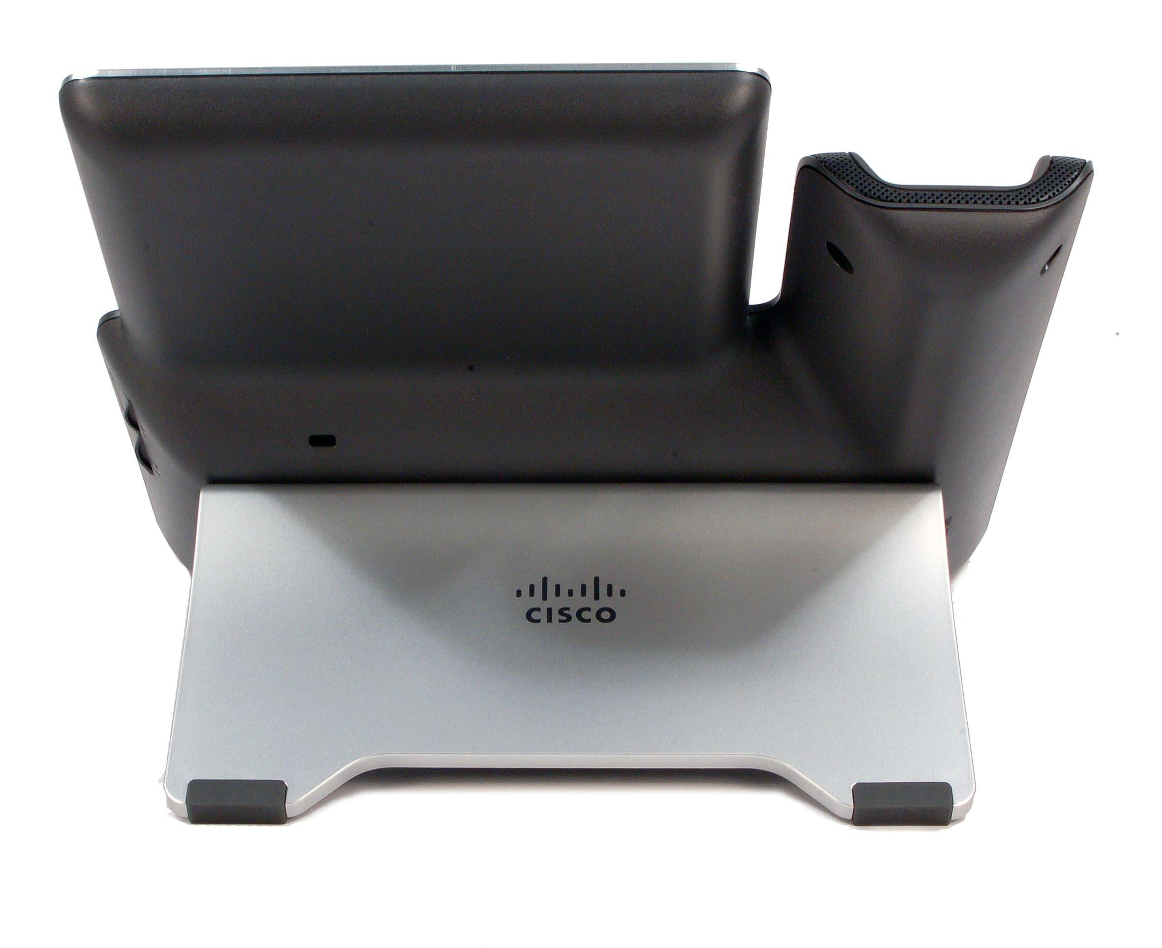
Click to zoom
Application Details
- Equipment Class
- DSS - Part 15 Spread Spectrum Transmitter
- Date of Grant
- Jun 05, 2014
- Application Purpose
- Original Equipment
- Date of Application
- Jun 05, 2014
- Equipment Note
- VIOP Phone w/ Handsfree Bluetooth
- Frequency Range
- 2402.00000000 - 2480.00000000
- Company
- Cisco Systems Inc
- Country
- United States
Documents & Files
Document Text
Text extracted from the exhibit documents filed with the FCC. Open a document above to read the original.
Users Manual
Americas Headquarters: Cisco Systems, Inc., 170 West Tasman Drive, San Jose, CA 95134-1706 USA Regulatory Compliance and Safety Information for Cisco Unified IP Phones This document provides international agency compliance, safety, and statutory information for Cisco Unified IP Phones. Contents This document contains the following sections: •Translated Safety Warnings, page 2 •Japanese Electric Appliance and Radio Laws, page 28 •Battery Safety Notices, page 28 •Using External Devices with Your Cisco Unified IP Phone, page 32 •European Directives, page 33 •Compliance and Safety Information, page 35 •Obtaining Documentation and Submitting a Service Request, page 44 2 Regulatory Compliance and Safety Information for Cisco Unified IP Phones Translated Safety Warnings This section repeats in multiple languages the basic warnings appropriate for Cisco Unified IP Phones. Statement 1071—Warning Definition WarningIMPORTANT SAFETY INSTRUCTIONS This warning symbol means danger. You are in a situation that could cause bodily injury. Before you work on any equipment, be aware of the hazards involved with electrical circuitry and be familiar with standard practices for preventing accidents. Use the statement number provided at the end of each warning to locate its translation in the translated safety warnings that accompanied this device. Statement 1071 SAVE THESE INSTRUCTIONS Waarschuwing BELANGRIJKE VEILIGHEIDSINSTRUCTIES Dit waarschuwingssymbool betekent gevaar. U verkeert in een situatie die lichamelijk letsel kan veroorzaken. Voordat u aan enige apparatuur gaat werken, dient u zich bewust te zijn van de bij elektrische schakelingen betrokken risico's en dient u op de hoogte te zijn van de standaard praktijken om ongelukken te voorkomen. Gebruik het nummer van de verklaring onderaan de waarschuwing als u een vertaling van de waarschuwing die bij het apparaat wordt geleverd, wilt raadplegen. BEWAAR DEZE INSTRUCTIES Varoitus TÄRKEITÄ TURVALLISUUSOHJEITA Tämä varoitusmerkki merkitsee vaaraa. Tilanne voi aiheuttaa ruumiillisia vammoja. Ennen kuin käsittelet laitteistoa, huomioi sähköpiirien käsittelemiseen liittyvät riskit ja tutustu onnettomuuksien yleisiin ehkäisytapoihin. Turvallisuusvaroitusten käännökset löytyvät laitteen mukana toimitettujen käännettyjen turvallisuusvaroitusten joukosta varoitusten lopussa näkyvien lausuntonumeroiden avulla. SÄILYTÄ NÄMÄ OHJEET Attention IMPORTANTES INFORMATIONS DE SÉCURITÉ Ce symbole d'avertissement indique un danger. Vous vous trouvez dans une situation pouvant entraîner des blessures ou des dommages corporels. Avant de travailler sur un équipement, soyez conscient des dangers liés aux circuits électriques et familiarisez-vous avec les procédures couramment utilisées pour éviter les accidents. Pour prendre connaissance des traductions des avertissements figurant dans les consignes de sécurité traduites qui accompagnent cet appareil, référez-vous au numéro de l'instruction situé à la fin de chaque avertissement. CONSERVEZ CES INFORMATIONS 3 Regulatory Compliance and Safety Information for Cisco Unified IP Phones Warnung WICHTIGE SICHERHEITSHINWEISE Dieses Warnsymbol bedeutet Gefahr. Sie befinden sich in einer Situation, die zu Verletzungen führen kann. Machen Sie sich vor der Arbeit mit Geräten mit den Gefahren elektrischer Schaltungen und den üblichen Verfahren zur Vorbeugung vor Unfällen vertraut. Suchen Sie mit der am Ende jeder Warnung angegebenen Anweisungsnummer nach der jeweiligen Übersetzung in den übersetzten Sicherheitshinweisen, die zusammen mit diesem Gerät ausgeliefert wurden. BEWAHREN SIE DIESE HINWEISE GUT AUF. Avvertenza IMPORTANTI ISTRUZIONI SULLA SICUREZZA Questo simbolo di avvertenza indica un pericolo. La situazione potrebbe causare infortuni alle persone. Prima di intervenire su qualsiasi apparecchiatura, occorre essere al corrente dei pericoli relativi ai circuiti elettrici e conoscere le procedure standard per la prevenzione di incidenti. Utilizzare il numero di istruzione presente alla fine di ciascuna avvertenza per individuare le traduzioni delle avvertenze riportate in questo documento. CONSERVARE QUESTE ISTRUZIONI Advarsel VIKTIGE SIKKERHETSINSTRUKSJONER Dette advarselssymbolet betyr fare. Du er i en situasjon som kan føre til skade på person. Før du begynner å arbeide med noe av utstyret, må du være oppmerksom på farene forbundet med elektriske kretser, og kjenne til standardprosedyrer for å forhindre ulykker. Bruk nummeret i slutten av hver advarsel for å finne oversettelsen i de oversatte sikkerhetsadvarslene som fulgte med denne enheten. TA VARE PÅ DISSE INSTRUKSJONENE Aviso INSTRUÇÕES IMPORTANTES DE SEGURANÇA Este símbolo de aviso significa perigo. Você está em uma situação que poderá ser causadora de lesões corporais. Antes de iniciar a utilização de qualquer equipamento, tenha conhecimento dos perigos envolvidos no manuseio de circuitos elétricos e familiarize-se com as práticas habituais de prevenção de acidentes. Utilize o número da instrução fornecido ao final de cada aviso para localizar sua tradução nos avisos de segurança traduzidos que acompanham este dispositivo. GUARDE ESTAS INSTRUÇÕES ¡Advertencia! INSTRUCCIONES IMPORTANTES DE SEGURIDAD Este símbolo de aviso indica peligro. Existe riesgo para su integridad física. Antes de manipular cualquier equipo, considere los riesgos de la corriente eléctrica y familiarícese con los procedimientos estándar de prevención de accidentes. Al final de cada advertencia encontrará el número que le ayudará a encontrar el texto traducido en el apartado de traducciones que acompaña a este dispositivo. GUARDE ESTAS INSTRUCCIONES 4 Regulatory Compliance and Safety Information for Cisco Unified IP Phones Varning! VIKTIGA SÄKERHETSANVISNINGAR Denna varningssignal signalerar fara. Du befinner dig i en situation som kan leda till personskada. Innan du utför arbete på någon utrustning måste du vara medveten om farorna med elkretsar och känna till vanliga förfaranden för att förebygga olyckor. An…
Text truncated - open the document above for the full version.
Users Manual
REVIEW DRAFT - CISCO CONFIDENTIAL Cisco IP Phone 8841, 8851, and 8861 User Guide for Cisco Unified Communications Manager 10.5 First Published: January25, 2014 Last Modified: May 05, 2014 Americas Headquarters Cisco Systems, Inc. 170 West Tasman Drive San Jose, CA 95134-1706 USA http://www.cisco.com Tel: 408 526-4000 800 553-NETS (6387) Fax: 408 527-0883 THE SPECIFICATIONSAND INFORMATION REGARDINGTHE PRODUCTSIN THIS MANUALARE SUBJECTTO CHANGEWITHOUTNOTICE.ALL STATEMENTS, INFORMATION, AND RECOMMENDATIONSIN THIS MANUALARE BELIEVEDTO BE ACCURATE BUT ARE PRESENTEDWITHOUTWARRANTYOF ANY KIND, EXPRESSOR IMPLIED.USERSMUSTTAKE FULL RESPONSIBILITYFOR THEIRAPPLICATION OF ANY PRODUCTS. THE SOFTWARE LICENSEAND LIMITEDWARRANTYFOR THE ACCOMPANYINGPRODUCTARE SET FORTH IN THE INFORMATION PACKETTHAT SHIPPEDWITH THE PRODUCTAND ARE INCORPORATED HEREINBY THIS REFERENCE.IF YOU ARE UNABLETO LOCATE THE SOFTWARE LICENSEOR LIMITEDWARRANTY, CONTACT YOURCISCOREPRESENTATIVE FOR A COPY. The followinginformationis for FCC complianceof Class A devices:This equipmenthas been tested and found to complywith the limits for a Class A digital device,pursuantto part 15 of the FCC rules. These limits are designedto providereasonableprotectionagainstharmfulinterferencewhen the equipmentis operatedin a commercialenvironment.This equipment generates,uses, and can radiateradio-frequencyenergy and, if not installedand used in accordancewith the instructionmanual,may cause harmfulinterferenceto radio communications. Operationof this equipmentin a residentialarea is likely to cause harmfulinterference,in which case users will be requiredto correctthe interferenceat their own expense. The followinginformationis for FCC complianceof Class B devices:This equipmenthas been tested and found to complywith the limits for a Class B digital device,pursuantto part 15 of the FCC rules. These limits are designedto providereasonableprotectionagainstharmfulinterferencein a residentialinstallation.This equipmentgenerates,uses and can radiateradio frequencyenergyand,ifnotinstalledandusedinaccordancewiththeinstructions,maycauseharmfulinterferencetoradiocommunications.However,thereisnoguaranteethatinterference will not occur in a particularinstallation.If the equipmentcauses interferenceto radio or televisionreception,which can be determinedby turningthe equipmentoff and on, users are encouragedto try to correctthe interferenceby using one or more of the followingmeasures: • Reorientor relocatethe receivingantenna. • Increasethe separationbetweenthe equipmentand receiver. • Connectthe equipmentinto an outlet on a circuit different from that to which the receiveris connected. • Consultthe dealer or an experiencedradio/TVtechnicianfor help. Modificationsto this productnot authorizedby Cisco could void the FCC approvaland negate your authorityto operatethe product The Cisco implementationof TCP headercompressionis an adaptationof a programdevelopedby the Universityof California,Berkeley(UCB)as part of UCB’s public domainversion of the UNIX operatingsystem.All rights reserved.Copyright © 1981, Regentsof the Universityof California. NOTWITHSTANDINGANYOTHERWARRANTYHEREIN,ALLDOCUMENTFILESANDSOFTWAREOFTHESESUPPLIERSAREPROVIDED"ASIS"WITHALLFAULTS. CISCOAND THE ABOVE-NAMEDSUPPLIERSDISCLAIMALL WARRANTIES,EXPRESSEDOR IMPLIED,INCLUDING,WITHOUTLIMITATION, THOSEOF MERCHANTABILITY,FITNESSFORAPARTICULARPURPOSEANDNONINFRINGEMENTORARISINGFROMACOURSEOFDEALING,USAGE,ORTRADEPRACTICE. IN NO EVENTSHALLCISCOOR ITS SUPPLIERSBE LIABLEFOR ANY INDIRECT, SPECIAL,CONSEQUENTIAL,OR INCIDENTAL DAMAGES,INCLUDING,WITHOUT LIMITATION, LOST PROFITSOR LOSS OR DAMAGETO DATA ARISINGOUT OF THE USE OR INABILITYTO USE THIS MANUAL,EVENIF CISCOOR ITS SUPPLIERS HAVE BEEN ADVISEDOF THE POSSIBILITYOF SUCHDAMAGES. AnyInternetProtocol(IP)addressesandphonenumbersusedinthisdocumentarenotintendedtobeactualaddressesandphonenumbers.Anyexamples,commanddisplayoutput,network topologydiagrams,andotherfiguresincludedinthedocumentareshownforillustrativepurposesonly.AnyuseofactualIPaddressesorphonenumbersinillustrativecontentisunintentional and coincidental. Cisco and the Cisco logo are trademarksor registeredtrademarksof Cisco and/or its affiliatesin the U.S. and other countries.To view a list of Cisco trademarks,go to this URL:http:// www.cisco.com/go/trademarks. Third-partytrademarksmentionedare the propertyof their respectiveowners.The use of the word partnerdoes not imply a partnership relationshipbetweenCisco and any other company. (1110R) © 2014 Cisco Systems,Inc. All rights reserved. CONTENTS CHAPTER 1 GettingStarted1 AccessibilityFeatures1 Cisco IP Phone 88411 Phone Connections1 Buttonsand Hardware2 Cisco IP Phone 88516 Phone Connections6 Buttonsand Hardware7 Cisco IP Phone 886110 Phone Connections10 Buttonsand Hardware12 Power Save and Power Save Plus15 Power Save15 Power Save Plus15 AdditionalInformation16 CHAPTER 2 PhoneSetup17 ConnectFootstand17 AdjustHandsetRest18 SecurePhone with Cable Lock18 CHAPTER 3 Basic Operations21 Clean Phone Display21 Make Calls22 PredialNumber22 Place Call Using Speakerphone22 Place Call Using Headset23 ReleaseCall and Start AnotherCall23 Cisco IP Phone 8841, 8851, and 8861 User Guide for Cisco Unified Communications Manager 10.5 iii Dial InternationalNumber23 Redial Number24 Navigateand Select Items24 View All Calls on Phone25 AnswerCalls25 AnswerOldest Call First26 Call Pickup26 AnswerCall Using PickUp27 AnswerCall Using Group PickUpand Phone Number28 AnswerCall Using Group PickUpand Group PickUpNumber28 AnswerCall Using Other PickUp29 AutomaticallyAnswerCalls29 Respondto Call Waiting Notification30 ManageCalls30 Divert Call30 TransferCall to AnotherNumber31 Toggle BetweenCalls BeforeCompletingTransfer31 Monitorand RecordCalls31 Call Forward32 ForwardAll Calls32 Mute Phone33 Hold Calls33 Swap BetweenActiveand Held Calls33 Put Call on Hold by AnsweringNew Call33 Respondto Hold ReversionNotification34 DetermineIf SharedLine Is On Hold34 RemoteHold34 Set Up Call Back Notific…
Text truncated - open the document above for the full version.
Attestation Statements
Cisco Systems, Inc. 170 West Tasman Drive San Jose, CA 95134-‐1706 Phone 408 526-‐4000 Fax: 408 526 –4100 http://www.cisco.com Cisco Systems, Inc. CP-8851 DFS Operation Attestation Letter To Whom It May Concern: The CP-8851 IP Phone only operates from 2402 to 2480 MHz band for North America (FCC and IC). Sincerely Gerard Thorpe Manager Test Development Engineering 408-526-4148
Cover Letter(s)
Cisco Systems, Inc. 170 West Tasman Drive San Jose, CA 95134-‐1706 Phone 408 526-‐4000 Fax: 408 526 –4100 http://www.cisco.com Request for Confidentiality Date: 05/24/2014 Subject: Confidentiality Request for: FCC ID: LDK88511056 Pursuant to FCC 47 CRF 0.457(d) and 0.459 and IC RSP-100, Section 10, the applicant requests that a part of the subject FCC application be held confidential. Type of Confidentiality Requested Exhibit Short Term Permanent Block Diagrams Short Term External Photos Short Term Permanent* 1 Internal Photos Short Term Permanent Operation Description/Theory of Operation Short Term Permanent Parts List & Placement/BOM Short Term Permanent Tune-Up Procedure Short Term Permanent Schematics Short Term Permanent* User’s Manual Cisco Systems, Inc. has spent substantial effort in developing this product and it is one of the first of its kind in industry. Having the subject information easily available to "competition" would negate the advantage they have achieved by developing this product. Not protecting the details of the design will result in financial hardship. Permanent Confidentiality: The applicant requests the exhibits listed above as permanently confidential be permanently withheld from public review due to materials that contain trade secrets and proprietary information not customarily released to the public. Short-Term Confidentiality: The applicant requests the exhibits selected above as short term confidential be withheld from public view for a period of ___(45) days from the date of the Grant of Equipment Authorization and prior to marketing. This is to avoid premature release of sensitive information prior to marketing or release of the product to the public. Applicant is also aware that they are responsible to notify ACB in the event information regarding the product or the product is made available to the public. ACB will then release the documents listed above for public disclosure pursuant to FCC Public Notice DA 04-1705. NOTE for Industry Canada Applications: The applicant understands that until such time that IC distinguishes between Short Term and Permanent Confidentiality, either type of marked exhibit above will simply be marked Confidential when submitted to IC. Sincerely Manager Test Development Engineering By: __________________________ ____Gerard Thorpe___ (Signature/Title 2 ) (Print name)
ID Label/Location Info
LABEL FINISHED COPY: NOTES: A) Material 338T-J1A ( WORLDMARK) Mat Ref: Ribbon: LABELS/TILE: TILES/PACK: LABELS/PACK: Matrix Strip:YN B) COLORSC) FONTS 1)1) 2) 2) 3) 4) 5) 6) 7) 8) 3) 4) 5) 6) 7) 8) DPW7424 CUSTOM BLACK VARNISH Title:________________________________Date:______________ Approved By:___________________________________________ DWG/PN:SEE AW:56-21190-01 REV.01 CUST. NAME: Tim Tao ARTWORK PROOF:#2 04/24/141 03 PFERFORATION LINE BETWEEN LABEL SET CP-8851-K9= 68-5282-01 X01 Made in China Dynamic(Auto test) (COO) Name all Countries, What are they? CP-8851 Modèle CAN ICES-3(B)/NMB-3(B) This Cisco CP-8851-K9 IP Phone may be connected to the Telecom Network PTC 220 / 14 / 042 US: 5B1IPNAN1076 FCC ID: LDK88511056 CANADA IC: 2461B-88511056 Model: CP-8851 For dimension callout see DWG# 471-00782-01 REV.01
ID Label/Location Info
Cisco Systems, Inc. 170 West Tasman Drive San Jose, CA 95134-‐1706 Phone 408 526-‐4000 Fax: 408 526 –4100 http://www.cisco.com Cisco Systems, Inc. CP-8851 Label and Location
RF Exposure Info
EDCS- 1404607 RF Exposure Study - Engineering Analysis per FCC 2.1093 Industry Canada RSS-102 CP-8851 Bluetooth IP Phone FCC ID: LDK88511056 IC ID: 2461B-88511056 Prepared By: Cisco Systems Inc 170 West Tasman San Jose, CA 95134 USA EDCS- 1404607 1.0: Attestation Statement of Compliance The Cisco Systems CP-8851 IP phone with 2.4GHz Bluetooth has been evaluated for Maximum Permissible Exposure in compliance with 47 Code of Federal Regulations 2.1093. The evaluation was in accordance with methodology as referenced in FCC Bulletin OET 65C (rev 01-01) by Compliance Certification Services This report serves as the additional technical analysis of the Cisco radio modules This study addresses the addition of an additional pair of transmitters using the data derived in the afore mentioned report # EDCS# 1403542 The limits used for this evaluation are in line with the recommendations of the World Health Organizations (WHO) International Committee on Non Ionizing Radiation Protection (ICNIRP) as well as the American National Standards Institute (ANSI) C95.1. The limits chosen are of General Population/Uncontrolled Exposure. This analysis also complies with the requirements stated in Industry Canada RSS-102 as well as the applicable Australian and New Zealand regulations. the following case scenarios were used : 2.4GHz Bluetooth This device must be installed to provide a separation distance of at least 20 cm from all persons. Installers must be provided with antenna installation and transmitter operating conditions for satisfying RF exposure compliance. Based on the study this case scenario, the General Population/Uncontrolled Exposure and the minimum recommended distance is around 20cm (8 inches) from the antenna. Jose Aguirre Cisco Systems Inc Corporate Compliance and Certifications 125 West Tasman Drive San Jose, CA 95134 Email: [email protected] EDCS- 1404607 2.0 EUT Description. CP-8851 2.4GHz Bluetooth IP phone 3.0 Methodology All calculations were made in accordance with ANSI C95.1, and FCC OET 65C. 4.0 Technical Requirements RSS-102 — Radio Frequency (RF) Exposure Compliance of Radio communication Apparatus (All Frequency Bands) 2.5.2 Exemption from Routine Evaluation Limits – RF Exposure Evaluation RF exposure evaluation is required if the separation distance between the user and the device's radiating element is greater than 20 cm, except when the device operates as follows: • below 1.5 GHz and the maximum e.i.r.p. of the device is equal to or less than 2.5 W; • at or above 1.5 GHz and the maximum e.i.r.p. of the device is equal to or less than 5 W. In these cases, the information contained in the RF exposure technical brief may be limited to information that demonstrates how the e.i.r.p. was derived. 4.2 RF Field Strength Limits for Devices Used by the General Public (Uncontrolled Environment) Frequency Range (MHz) Electric Field (V/m rms) Magnetic Field (A/m rms) Power Density (W/m 2 ) Averaging Time (minutes) 0.003-1 280 2.19 - 6 1-10 280/f 2.19/f - 6 10-30 28 2.19/f - 6 30-300 28 0.073 2 * 6 300-1500 1.585 f 0.5 0.0042 f 0.5 f/150 6 1500-15000 61.4 0.163 10 6 15000-150000 61.4 0.163 10 616000/f 1.2 150000-300000 0.158 f 0.5 4.21 x 10 -4 f 0.5 6.67 x 10 -5 f 616000/f 1.2 Note: f is frequency in MHz. * Power density limit is applicable at frequencies greater than 100 MHz. EDCS- 1404607 FCC Limits for Maximum Permissible Exposure (MPE) (A) Limits for Occupational/Controlled Exposure Frequency Electric Field Magnetic Field Power Density Averaging Time Range Strength (E) Strength (H) (S) |E| 2 , |H| 2 or S (MHz) (V/m) (A/m) (mW/cm 2 ) (minutes) 0.3-3.0 614 1.63 (100)* 6 3.0-30 1842/f 4.89/f (900/f 2 )* 6 30-300 61.4 0.163 1.0 6 300-1500 -- -- f/300 6 1500-100,000 -- -- 5 6 (B) Limits for General Population/Uncontrolled Exposure Frequency Electric Field Magnetic Field Power Density Averaging Time Range Strength (E) Strength (H) (S) |E| 2 , |H| 2 or S (MHz) (V/m) (A/m) (mW/cm 2 ) (minutes) 0.3-1.34 614 1.63 (100)* 30 1.34-30 824/f 2.19/f (180/f 2 )* 30 30-300 27.5 0.073 0.2 30 300-1500 -- -- f/1500 30 1500-100,000 -- -- 1.0 30 f = frequency in MHz *Plane-wave equivalent power density NOTE 1: See Section 1 for discussion of exposure categories. NOTE 2: The averaging time for General Population/Uncontrolled exposure to fixed transmitters is not applicable for mobile and portable transmitters. See 47 CFR §§2.1091 and 2.1093 on source-based time-averaging requirements for mobile and portable transmitters. EDCS- 1404607 5.0 Calculations 5.1 The Power Density Power Density (mW/cm2) is calculated as follows: S = PG(Duty Cycle) / 4πR 2 (Equation 1) Solve for R R= sqrt ( !"!"#$ !"!#$ !" ! ) (Equation 2) Where: S = power density (in appropriate units, e.g. mW/cm2) P = power input to the antenna (in appropriate units, e.g., mW) G = power gain of the antenna in the direction of interest relative to an isotropic radiator R = distance to the center of radiation of the antenna (appropriate units, e.g., cm) 5.2 Maximum EIRP For RSS102 section 2.5.2 an evaluation of the maximum EIRP is required The calculation used to determine EIRP is as follows: EIRP = PG (Equation 4) Where: EIRP = equivalent isotropic radiated power P = power input to the antenna (in appropriate units, e.g., mW) G = power gain of the antenna in the direction of interest relative to an isotropic radiator EDCS- 1404607 6.0 Results Test Reports used in evaluation are : EDCS# 1403542 Calculated EIRP Tx Frequency (MHz) Peak Tx Power (dBm) Radio Power (mW) Ant Gain (dBi) Ant Gain (mW eq) EIRP mW EIRP W Limit W Tx1 2402 -2480 4.31 2.70 3.11 2.05 5.53 0.0055 < 5 MPE Calculations Tx Frequency (MHz) MPE Distance (cm) Peak Tx Power (dBm) Radio Power (mW) Ant Gain (dBi) Ant Gain (mW eq) Duty Cycle Power Density (mW/cm^2) Limit (mW/cm^2) % of Std Tx1 2402 -2480 20 4.31 2.70 3.11 2.05 1 0.0011 1 0.11 Note 1 – WLAN radio assume worst case 100% duty cycle. Using Equation 2 to determine the MPE distance Tx Frequency (MHz) Power Density (mW/cm^2) Peak Tx…
Text truncated - open the document above for the full version.
Test Report
Radio Intentional Test Report No: EDCS-1403542 FCC ID: LDK88511056 IC ID: 2461B-88511056 Page No: 1 of 92 This document is uncontrolled. Please refer to the electronic copy within EDCS for the most up to date version. Cisco Systems, Inc. Company Confidential Radio Intentional EMC Test Report: EDCS-1403542 For CP-8851 Bluetooth Module Against the following Specifications : 47 CFR 15.247, 15.205, 15.209 FCC ID: LDK88511056 and RSS-210 Issue 8, RSS-Gen Issue 3 IC ID: 2461B-88511056 Cisco Systems EMC Laboratory 170 West Tasman Drive San Jose, CA 95134 Author: Danh Le Approved By: Dilip Patel Title: Regulatory Compliance Manager This report replaces any previously entered test report under EDCS-1403542 This test report has been electronically authorized and archived using the CISCO Engineering Document Control system. Radio Intentional Test Report No: EDCS-1403542 FCC ID: LDK88511056 IC ID: 2461B-88511056 Page No: 2 of 92 This document is uncontrolled. Please refer to the electronic copy within EDCS for the most up to date version. Cisco Systems, Inc. Company Confidential SECTION 1: OVERVIEW .......................................................................................................................................... 3 TEST SUMMARY .......................................................................................................................................................... 3 SECTION 2: ASSESSMENT INFORMATION ....................................................................................................... 4 2.3 REPORT ISSUE DATE ............................................................................................................................................. 5 2.4 TESTING FACILITIES .............................................................................................................................................. 5 2.6 EUT DESCRIPTION ................................................................................................................................................ 6 2.7 SCOPE OF ASSESSMENT ......................................................................................................................................... 6 2.8 UNITS OF MEASUREMENT ..................................................................................................................................... 6 2.9 REPORT TEMPLATE CONTROL NO. ........................................................................................................................ 7 SECTION 3: RESULT SUMMARY .......................................................................................................................... 8 3.1 RESULTS SUMMARY TABLE .................................................................................................................................. 8 SECTION 4: SAMPLE DETAILS ............................................................................................................................ 10 4.1 SAMPLE DETAILS ................................................................................................................................................ 10 4.2 SYSTEM DETAILS ................................................................................................................................................ 10 4.3 MODE OF OPERATION DETAILS ........................................................................................................................... 10 4.4 TEST MODE, MODULATION AND DATA PACKET TYPE DESCRIPTION ................................................................. 10 4.4.1 TEST MODE AND WORST CASE ......................................................................................................................... 11 SECTION 5: MODIFICATIONS ............................................................................................................................. 12 5.1 SAMPLE MODIFICATIONS PERFORMED DURING ASSESSMENT ............................................................................ 12 APPENDIX A: FORMAL TEST RESULTS ..................................................................................................... 13 A.1 OCCUPIED BANDWIDTH (20DB BANDWIDTH & 99% BANDWIDTH) ........................................................... 13 A.2 PEAK OUTPUT POWER ................................................................................................................................ 19 A.3 CARRIER FREQUENCY SEPARATION ........................................................................................................... 34 A.4 NUMBER OF HOPPING FREQUENCIES .......................................................................................................... 36 A.5 DWELL TIME / AVERAGE TIME OF OCCUPANCY ......................................................................................... 39 A.7 CONDUCTED SPURIOUS EMISSIONS ............................................................................................................ 64 A.8 RESTRICTED BAND (CONDUCTED) ............................................................................................................. 70 A.9 RECEIVER RADIATED SPURIOUS EMISSIONS .............................................................................................. 73 A.10 TRANSMITTER RADIATED SPURIOUS EMISSIONS ........................................................................................ 78 A.11 CONDUCTED EMISSIONS FOR AC POWER ADAPTER ................................................................................... 85 APPENDIX B: ABBREVIATION KEY AND DEFINITIONS ....................................................................... 89 APPENDIX C: LIST OF TEST EQUIPMENT USED TO PERFORM THE TEST .................................... 90 APPENDIX D: TEST PROCEDURES .............................................................................................................. 92 Radio Intentional Test Report No: EDCS-1403…
Text truncated - open the document above for the full version.
Test Setup Photos
Test Setup / EUT’s Photos Company Name: Cisco Systems, Inc Model(s): CP-‐8851, CP-‐8861 Physical Test Configuration Photos Title: Radiated Test Configuration from 30M -‐ 1000MHz Title: Radiated Test Configuration from 1 -‐ 18GHz Physical Test Configuration Photos Title: Bluetooth & RF Conducted Test Setup Title: AC Mains Conducted Test Setup Title: DFS Test Setup
Contact Information
Applicant
Samuel Kim(Manager, Engineering)
Test Firm
Cisco Systems, Inc.Dave Wilson
Technical Specifications
| # | Rule Parts | Frequency Range | Power Output |
|---|---|---|---|
| 1 | 15C | 2.40 GHz - 2.48 GHz | 2.70 mW |
Other Applications from Cisco Systems Inc

LDKJ98213058
May 25, 2026Wireless Phone
Equipment Class
DSS - Part 15 Spread Spectrum TransmitterLDKIW9165E
Aug 20, 2024Wi-Fi 6E Outdoor Access Point
Equipment Class
6SD - 15E 6 GHz Standard Power Access PointLDKIW9165DH
Aug 05, 2024Wi-Fi 6E Outdoor Access Point
Equipment Class
6SD - 15E 6 GHz Standard Power Access PointLDKUSBC2857
Jul 22, 2024Cisco Headset USB-C Adapter
Equipment Class
DSS - Part 15 Spread Spectrum TransmitterLDKESPRD2922
May 09, 2024UC Phone
Equipment Class
NII - Unlicensed National Information Infrastructure TX