LDK9KG80001WiFi module
Cisco Systems Inc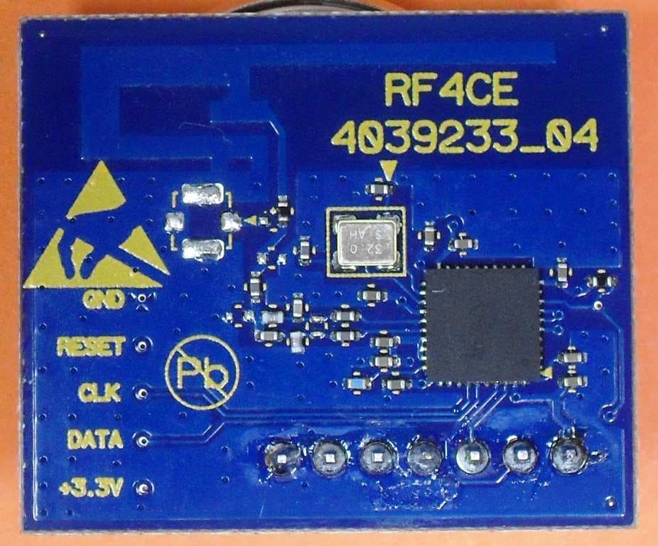
Click to zoom
Application Details
- Equipment Class
- DXT - Part 15 Low Power Transceiver, Rx Verified
- Date of Grant
- Sep 11, 2012
- Application Purpose
- Original Equipment
- Date of Application
- Sep 10, 2012
- Equipment Note
- WiFi module
- Frequency Range
- 2425.00000000 - 2475.00000000
- Company
- Cisco Systems Inc
- Country
- United States
Documents & Files
Document Text
Text extracted from the exhibit documents filed with the FCC. Open a document above to read the original.
Users Manual
IMPORTANT SAFETY INSTRUCTIONS Notice to Installers The servicing instructions in this notice are for use by qualifi ed service personnel only. To reduce the risk of electric shock, do not perform any servicing other than that contained in the operating instructions, unless you are qualifi ed to do so. 20080814_Installer820 1) Read these instructions. 2) Keep these instructions. 3) Heed all warnings. 4) Follow all instructions. 5) Do not use this apparatus near water. 6) Clean only with dry cloth. 7) Do not block any ventilation openings. Install in accordance with the manufacturer’s instructions. 8) Do not install near any heat sources such as radiators, heat registers, stoves, or other apparatus (including amplifiers) that produce heat. 9) Do not defeat the safety purpose of the polarized or grounding-type plug. A polarized plug has two blades with one wider than the other. A grounding-type plug has two blades and a third grounding prong. The wide blade or the third prong are provided for your safety. If the provided plug does not fit into your outlet, consult an electrician for replacement of the obsolete outlet. 10) Protect the power cord from being walked on or pinched particularly at plugs, convenience receptacles, and the point where they exit from the apparatus. 11) Only use attachments/accessories specified by the manufacturer. 12) Use only with the cart, stand, tripod, bracket, or table specified by the manufacturer, or sold with the apparatus. When a cart is used, use caution when moving the cart/apparatus combination to avoid injury from tip-over. 13) Unplug this apparatus during lightning storms or when unused for long periods of time. 14) Refer all servicing to qualified service personnel. Servicing is required when the apparatus has been damaged in any way, such as a power-supply cord or plug is damaged, liquid has been spilled or objects have fallen into the apparatus, the apparatus has been exposed to rain or moisture, does not operate normally, or has been dropped. Power Source Warning A label on this product indicates the correct power source for this product. Operate this product only from an electrical outlet with the voltage and frequency indicated on the product label. If you are uncertain of the type of power supply to your home or business, consult your service provider or your local power company. The AC inlet on the unit must remain accessible and operable at all times. Note to System Installer WARNING TO PREVENT FIRE OR ELECTRIC SHOCK, DO NOT EXPOSE THIS UNIT TO RAIN OR MOISTURE. For this apparatus, the coaxial cable shield/screen shall be grounded as close as practical to the point of entry of the cable into the building.For products sold in the US and Canada, this reminder is provided to call the system installer's attention to Article 820-93 and Article 820-100 of the NEC (or Canadian Electrical Code Part 1), which provides guidelines for proper grounding of the coaxial cable shield. This symbol is intended to alert you that uninsulated voltage within this product may have sufficient magnitude to cause electric shock.Therefore, it is dangerous to make any kind of contact with any inside part of this product. Ce symbole a pour but d’alerter toute personne qu’un contact avec une pièce interne de ce produit, sous tension et non isolée, pourrait être suffisant pour provoquer un choc électrique. Il est donc dangereux d’être en contact avec toute pièce interne de ce produit. This symbol is intended to alert you of the presence of important operating and maintenance (servicing) instructions in the literature accompanying this product. Ce symbole a pour but de vous avertir qu’une documentation importante sur le fonctionnement et l’entretien accompagne ce produit. CAUTION: To reduce the risk of electric shock, do not remove cover (or back). No user-serviceable parts inside. Refer servicing to qualified service personnel. Ground the Product WARNING: Avoid electric shock and fi re hazard! If this product connects to coaxial cable wiring, be sure the cable system is grounded (earthed). Grounding provides some protection against voltage surges and built-up static charges. Outdoor Grounding System If this product connects to an outdoor antenna or cable system, be sure the antenna or cable system is grounded (earthed). This provides some protection against voltage surges and built-up static charges. Article 810 of the National Electric Code (NEC) ANSI/NFPA No. 70-1990, provides the following information: • Grounding of the mast and supporting structure • Grounding the lead-in wire to an antenna discharge unit • Size of the grounding conductors • Location of the antenna-discharge unit • Connection to grounding electrodes • Requirements for the grounding electrodes (see the following antenna grounding diagram as recommended by NEC ANSI/NFPA 70) WARNING: Avoid electric shock and fi re hazard! Do not locate an outside antenna system in the vicinity of overhead power lines or power circuits. Touching power lines or circuits might be fatal. Eliminate AC Power/Mains Overloads WARNING: Avoid electric shock and fi re hazard! Do not overload AC power/ mains, outlets, extension cords, or integral convenience receptacles. For products that require battery power or other power sources to operate them, refer to the operating instructions for those products. Handling Disposable Batteries This product may contain disposable batteries. Heed the following warning and follow the Battery Safety and Battery Disposal instructions below. WARNING: There is danger of explosion if the battery is mishandled or incorrectly replaced. Replace only with the same type of battery. Do not disassemble it or attempt to recharge it outside the system. Do not crush, puncture, dispose of in fi re, short the external contacts, or expose to water or other liquids. Dispose of the battery in accordance with local regulations and instructions from your service provider. Battery Safety • Insert batteries correctly. T…
Text truncated - open the document above for the full version.
Users Manual
Cisco Systems, Inc. 678 277-1120 5030 Sugarloaf Parkway, Box 465447 770 722-2009 Lawrenceville, GA 30042 www.cisco.com Cisco and the Cisco logo are trademarks or registered trademarks of Cisco and/or its affi liates in the U.S. and other countries. A listing of Cisco’s trademarks can be found at www.cisco.com/go/trademarks . CableCARD and M-Card are trademarks of Cable Television Laboratories, Inc.Manufactured under license from Dolby Laboratories. Dolby and the double-D symbol are trademarks of Dolby Laboratories.HDMI, the HDMI logo, and High-Defi nition Multimedia Interface are trademarks or registered trademarks of HDMI Licensing LLC in the United States and other count ries. Rovi is a trademark of Rovi Corporation.MoCA is a trademark of the Multimedia over Coax Alliance.Other third party trademarks mentioned are the property of their respective owners.The use of the word partner does not imply a partnership relationship between Cisco and any other company. (1009R)© 2012 Cisco and/or its affi liates. All rights reserved. June 2012 Printed in United States of America Part Number OL-26440-01 Cisco Explorer 9800 Hybrid Video Gateway Series Quick Reference Guide MENU EXIT LIST INFO VOL - VOL+ OK CH - CH+ 9845HDC About the Remote Control 1. Power On and Off 2. Access specifi c channels 3. Access last channel viewed 4. Scroll through menu pages 5. Scroll through channels 6. Scroll through menu items 7. Exit menus 8. Access video-on-demand (VOD) window* 9. Access audio/video options 10. Fast-forward VOD program* 11. Access the Settings screen 12. Toggle between TV and Radio modes 13. Access color-coded screen options 14. Pause VOD program* 15. Stop VOD program* 16. Rewind VOD program* 17. Play VOD program* 18. Access menus 19. Access Electronic Program Guide (EPG) 20. Access Navigator Bar 21. Select menu item22. Adjust volume 23. Mute volume 24. Access Favorite List* If VOD services are authorized by your service provider Open Source GNU GPL StatementCisco Explorer 9800 Hybrid Video Gateways contain(s), in part, certain free/open source software (“Free Software”) under licenses which generally make the source code available for free copy, modifi cation, and redistribution. Examples of such licenses include all the licenses sponsored by the Free Software Foundation (e.g. GNU General Public License (GPL), GNU Lesser General Public License (LGPL), Berkeley Software Distribution (BSD), the MIT licenses and diff erent versions of the Mozilla and Apache licenses). To fi nd additional information regarding the Free Software, including a copy of the applicable license and related information, please go to: (i) for North America http://www.cisco.com/web/consumer/support/ open_source.html , or (ii) for outside North America http:// www.cisco.com/web/consumer/support/open_source.html#~international . Once at the site, search for the product listing and click on the related items identifi ed. If you have any questions or problems accessing any of the links, please contact: [email protected] . AVC VIDEO LICENSEWith respect to each AVC/H.264 product, we are obligated to provide the following notice:THIS PRODUCT IS LICENSED UNDER THE AVC PATENT PORTFOLIO LICENSE FOR THE PERSONAL USE OF A CONSUMER OR OTHER USES IN WHICH IT DOES NOT RECEIVE REMUNERATION TO (i) ENCODE VIDEO IN COMPLIANCE WITH THE AVC STANDARD (“AVC VIDEO”) AND/OR (ii) DECODE AVC VIDEO THAT WAS ENCODED BY A CONSUMER ENGAGED IN A PERSONAL ACTIVITY AND/OR WAS OBTAINED FROM A VIDEO PROVIDER LICENSED TO PROVIDE AVC VIDEO. NO LICENSE IS GRANTED OR SHALL BE IMPLIED FOR ANY OTHER USE. ADDITIONAL INFORMATION MAY BE OBTAINED FROM MPEG LA, L.L.C. SEE HTTP://WWW.MPEGLA.COM . Accordingly, please be advised that service providers, content providers, and broadcasters may be required to obtain a separate use license from MPEG LA prior to any use of AVC/H.264 encoders and/or decoders. ROVI CORPORATION COPYRIGHT NOTICEThis product incorporates copyright protection technology that is protected by U.S. patents and other intellectual property rights. Use of this copyright protection technology must be authorized by Rovi Corporation, and is intended for home and other limited viewing uses only unless otherwise authorized by Rovi Corporation. Reverse engineering or disassembly is prohibited.DisclaimerCisco Systems, Inc. assumes no responsibility for errors or omissions that may appear in this guide. We reserve the right to change this guide at any time without notice. T15194 1378 10 11 92564 12 131922141524162017211823 WelcomeThe Cisco® Explorer® 9800 Hybrid Video Gateway Series receive and deliver digital signals, and deliver high-defi nition programming in exceptional picture and audio quality. Use the simple user interface to access favorite channels and parental control services. Contact your service provider for information about these and other available services. Use the instructions in this guide to install the gateway and to access your program services.The consumer support website provides news and information about this product. For more information, please refer to: http://www.cisco.com/web/consumer/ support/index.html Safety FirstBefore using this gateway read the IMPORTANT SAFETY INSTRUCTIONS included with your gateway.Avoid Screen Burn-InImages such as letterbox bars or side bars, bright closed-captioning backgrounds, station logos, or any other stationary images may cause the TV screen to age unevenly and cause damage to your TV. Refer to the user guide that came with your TV for more information about screen burn-in.Automatic Software UpdatesA message appears on the TV screen when the gateway and the M-Card™ module are receiving software updates. In addition, download information also appears on the front panel of the gateway during these updates. Wait for the current time to display on the front panel before continuing. When the time appears, the update is complete.Performance TipsIf the gateway does not perform as expec…
Text truncated - open the document above for the full version.
ID Label/Location Info
436758 D C B D A C B 1 3241567 2 SIZE SCALE DWG NO. REV SERVICE PROVIDER BUSINESS Lawrenceville, Georgia USA SHEET Pro/E DWG TYPE TITLE 8 A .125 [3,18] .125 [3,18] R.13 [3,3] 1.50 [38,1] 3.00 [76,2] ALL DIMENSIONS ARE IN INCHES [MM] UNLESS OTHERWISE SPECIFIED TOLERANCES 3 PLACE DECIMAL .005 2 PLACE DECIMAL .02 1 PLACE DECIMAL .1 TOL ON ANGLES 0 30' SURFACE ROUGHNESS: 125 BREAK SHARP EDGES AND CORNERS INTERPRET DIM AND TOL PER ASME Y14.5M THIRD ANGLE PROJECTION IDENTIFYING OR PART NO. MAT'L SPEC AND SIZE OR COMPONENT VALUE DESCRIPTION PART NO. QTY REQD ITEM NO. REVISION HISTORY APPROVEDDATEDESCRIPTIONREV B.ROGERS29-Mar-12171834 DSCHRODTA ORIGINATORDSCHRODT ORIGINATION DATE29-Mar-12 APPROVER INFORMATION MAINTAINED IN AGILE OR OTHER PDM SYSTEM ENVIRONMENTAL REGULATORY COMPLIANCE REQUIREMENT THE MATERIALS AND PROCESSES USED TO DEVELOP, PRODUCE AND/OR MANUFACTURE PARTS AND PRODUCTS SHALL COMPLY WITH ALL APPLICABLE LAWS, REGULATIONS AND ORDINANCES WHICH REGULATE USE OF PRODUCT MATERIALS OR WHICH IMPACT, IN WHOLE OR IN PART, A PRODUCT'S SALE OR PLACEMENT INTO COMMERCE BY OR ON BEHALF OF CISCO. ADDITIONALLY, ALL PARTS, PRODUCTS AND OPERATIONS WILL COMPLY WITH CISCO ENVIRONMENTAL SPECIFICATIONS IN EFFECT AT TIME OF MANUFACTURE, INCLUDING THE FOLLOWING: EDCS-661823 CISCO CONTROLLED SUBSTANCES SPECIFICATION EDCS-627058 COMPLIANCE SPECIFICATION FOR BATTERIES AND PRODUCTS CONTAINING BATTERIES EDCS-886022 CISCO ENVIRONMENTAL PACKAGING SPECIFICATION THIS DOCUMENT CONTAINS INFORMATION WHICH IS CONFIDENTIAL TO CISCO / SCIENTIFIC ATLANTA AND IS TO BE USED FOR THE PURPOSE IN WHICH IT HAS BEEN SUPPLIED 1 OF 14.00 A 7023729 D ASSY, LABEL, BOTTOM, FCC, 1.5X3, 9KG8 A/0/Released 4043800_ASSY_LBL_BTM_FCC_9KG8MODEL: A/1/WIP 7023729_DWG_LBL_BTM_FCC_9KG8DWG: Rev/Iteration/StateFILE NAME CAD DATA SEE SEPARATE PARTS LIST 4043800 SEE ARTWORK FILE 7023729 FOR TRUE REPRESENTATION NOTES: 1. MATERIAL: MAKE FROM CISCO PART NUMBER 4009156. 2. CUT LABEL SHOWN FOR CLARITY. 3. PRINTING OF THIS LABEL IS TO BE DONE USING THERMAL TRANSFER RIBBON (MADE FROM RESIN). THE LAYOUT, FONT TYPE AND POINT SIZE IS APPROXIMATELY AS SHOWN. 4. TEXT COLOR: BLACK BACKGROUND: WHITE 5. ARTWORK SHOWN IS FOR REFERENCE ONLY. ACTUAL ARTWORK IS ARCHIVED IN AGILE. SCALE: 4.00 REVERSE PRINT THIS AREA WITH BLACK BACKGROUND AND WHITE TEXT SCALE 1.000
ID Label/Location Info
3241 DD 234 C B C A B 1 SIZE SCALE DWG NO. REV SERVICE PROVIDER BUSINESS Lawrenceville, Georgia USA SHEET Pro/E DWG TYPE TITLE A REVISION HISTORY APPROVEDDATEDESCRIPTIONREV BRAD ROGERS26-JUN-12173499 CORNELL LEWISA BRAD ROGERS14-Aug-12XXXXXX DSCHRODTB ALL DIMENSIONS ARE IN INCHES [MM] UNLESS OTHERWISE SPECIFIED TOLERANCES 3 PLACE DECIMAL .005 2 PLACE DECIMAL .02 1 PLACE DECIMAL .1 TOL ON ANGLES 0 30' SURFACE ROUGHNESS: 125 BREAK SHARP EDGES AND CORNERS INTERPRET DIM AND TOL PER ASME Y14.5M THIRD ANGLE PROJECTION 1 OF 12.00 B 7023393 C PCB,BLUETOOTH DAUGHTERBOARD,7PIN-IF B/0/WIP4043229_RF4CE_9KG8MODEL: B/0/WIP7023393_ASSY_RF4CEDWG: Rev/Iteration/StateFILE NAME CAD DATA THIS DOCUMENT CONTAINS INFORMATION WHICH IS CONFIDENTIAL TO CISCO / SCIENTIFIC ATLANTA AND IS TO BE USED FOR THE PURPOSE IN WHICH IT HAS BEEN SUPPLIED ENVIRONMENTAL REGULATORY COMPLIANCE REQUIREMENT THE MATERIALS AND PROCESSES USED TO DEVELOP, PRODUCE AND/OR MANUFACTURE PARTS AND PRODUCTS SHALL COMPLY WITH ALL APPLICABLE LAWS, REGULATIONS AND ORDINANCES WHICH REGULATE USE OF PRODUCT MATERIALS OR WHICH IMPACT, IN WHOLE OR IN PART, A PRODUCT'S SALE OR PLACEMENT INTO COMMERCE BY OR ON BEHALF OF CISCO. ADDITIONALLY, ALL PARTS, PRODUCTS AND OPERATIONS WILL COMPLY WITH CISCO ENVIRONMENTAL SPECIFICATIONS IN EFFECT AT TIME OF MANUFACTURE, INCLUDING THE FOLLOWING: EDCS-661823 CISCO CONTROLLED SUBSTANCES SPECIFICATION EDCS-627058 COMPLIANCE SPECIFICATION FOR BATTERIES AND PRODUCTS CONTAINING BATTERIES EDCS-886022 CISCO ENVIRONMENTAL PACKAGING SPECIFICATION APPROVER INFORMATION MAINTAINED IN AGILE OR OTHER PDM SYSTEM 26-Jun-12ORIGINATION DATE C. LEWISORIGINATOR CAGE CODE IDENTIFYING OR PART NO. MAT'L SPEC AND SIZE OR COMPONENT VALUE DESCRIPTION PART NO. QTY REQD ITEM NO. HOLDER, BLUETOOTH, 4KG7403654611 PCB,BLUETOOTH DAUGHTERBOARD,7PIN-IF403922912 LABEL, FCC ID/IC4XXXXXX13 1 3 2
ID Label/Location Info
SIZE SCALE DWG NO. REV SERVICE PROVIDER BUSINESS Lawrenceville, Georgia USA SHEET Pro/E DWG TYPE TITLE 123456 123456 A B C D A B C D .125 .062 6 31.66 R1 REVISION HISTORY APPROVEDDATEDESCRIPTIONREV BRAD ROGERS14-Aug-12XXXXXXX DSCHRODT01 CAGE CODE IDENTIFYING OR PART NO. MAT'L SPEC AND SIZE OR COMPONENT VALUE DESCRIPTION CISCO PART NO. QTY REQD ITEM NO. 1 OF 14.00 00 4XXXXXX A3 LABEL, FCC ID/IC 00/0/WIP 4XXXXXX_LBL_FCC_ID_BTMODEL: 00/0/WIP 4XXXXX_LBL_FCC_ID_BTDWG: Rev/Iteration/State FILE NAME CAD DATA ORIGINATORDSCHRODT ORIGINATION DATE14-Aug-12 APPROVER INFORMATION MAINTAINED IN AGILE OR OTHER PDM SYSTEM ENVIRONMENTAL REGULATORY COMPLIANCE REQUIREMENT THE MATERIALS AND PROCESSES USED TO DEVELOP, PRODUCE AND/OR MANUFACTURE PARTS AND PRODUCTS SHALL COMPLY WITH ALL APPLICABLE LAWS, REGULATIONS AND ORDINANCES WHICH REGULATE USE OF PRODUCT MATERIALS OR WHICH IMPACT, IN WHOLE OR IN PART, A PRODUCT'S SALE OR PLACEMENT INTO COMMERCE BY OR ON BEHALF OF CISCO. ADDITIONALLY, ALL PARTS, PRODUCTS AND OPERATIONS WILL COMPLY WITH CISCO ENVIRONMENTAL SPECIFICATIONS IN EFFECT AT TIME OF MANUFACTURE, INCLUDING THE FOLLOWING: EDCS-661823 CISCO CONTROLLED SUBSTANCES SPECIFICATION EDCS-627058 COMPLIANCE SPECIFICATION FOR BATTERIES AND PRODUCTS CONTAINING BATTERIES EDCS-886022 CISCO ENVIRONMENTAL PACKAGING SPECIFICATION THIS DOCUMENT CONTAINS INFORMATION WHICH IS CONFIDENTIAL TO CISCO AND IS TO BE USED FOR THE PURPOSE IN WHICH IT HAS BEEN SUPPLIED ALL DIMENSIONS ARE IN MILLIMETERES [INCHES] UNLESS OTHERWISE SPECIFIED TOLERANCES .12 TOL ON ANGLES 0 30' SURFACE ROUGHNESS: 3.2 BREAK SHARP EDGES AND CORNERS INTERPRET DIM AND TOL PER ASME Y14.5M THIRD ANGLE PROJECTION NOTES: 1. MATERIAL: WHITE POLYESTER STOCK WITH ADHESIVE BACKING. 2. PRINT BAR CODE LABELS USING THERMAL TRANSFER RIBBON. BARCODE LAYOUT, FONT, AND SIZE IS APPROXIMATELY AS SHOWN. 3. USE CURRENT BAR CODE 128 CONVENTIONS. TEXT COLOR: BLACK BACKGROUND: WHITE 5. PRINTING OF THIS LABEL IS TO BE DONE USING THERMAL TRANSFER RIBBON (MADE FROM RESIN). THE LAYOUT, FONT TYPE AND POINT SIZE IS APPROXIMATELY AS SHOWN. ROLL FEED DIRECTION 4 4
Test Report
Client: Product Designation: RF4CE Report Number: 100691933ATL-001 All services undertaken are subject to the following general policy: This report is for the exclusive use of Intertek's Client and is provided pursuant to the agreement between Intertek and its Client. Intertek's responsibility and liability are limited to the terms and conditions of the agreement. Intertek assumes no liability to any party, other than to the Client in accordance with the agreement, for any loss, expense or damage occasioned by the use of this report. Only the Client is authorized to copy or distribute this report and then only in its entirety. Any use of the Intertek name or one of its marks for the sale or advertisement of the tested material, product or service must first be approved in writing by Intertek. The observations and test results in this report are relevant only to the sample tested. This report by itself does not imply that the material, product, or service is or has ever been under an Intertek certification program. This report must not be used to claim product endorsement by A2LA, NIST, or any agency of the US Government. Tested by: Tests performed by:Report reviewed by: Standard: Jeremy O. Pickens Senior Staff Engineer Troy J. Ihle EMC Project Engineer CISCO 5030 Sugarloaf Parkway Lawrenceville, GA 30044 Contact: Bob Lyall Phone: 770.236.7439 Fax: 770.236.3089 [email protected] TEST REPORT April 27, 2012 Intertek Testing Services NA Inc. 1950 Evergreen Blvd., Suite 100 Duluth, GA 30096 FCC 15.249 - Operation within the bands 902-928 MHz, 2400-2483.5 MHz, 5725-5875 MHZ, and 24.0-24.25 GHz. RSS-210, Issue 7, 2007 Page 1 of 25EMC Report for CISCO on the RF4CE 04/27/2012Report Number: 100691933ATL-001Issued: Intertek 2.0 Test Summary 1.0 Introduction and Conclusion Test DateTest Full NameResultSection System setup including cable interconnection details, support equipment and simplified block diagram. (System Setup)4.0 Overview of EUT (Low Power Transmitters) (FCC 15C - EUT Overview)5.0 03/30/2012Radiated emissions (E-field) for low power intentional radiators. (Radiated Emissions LPD)PASS6.0 03/30/2012Occupied Bandwidth (FCC Part 2.1049)PASS7.0 15.249(b): Requirements for fixed, point-to-point operation (FCC 15C - 15.249(b))8.0 Additional provisions to the general radiated emission limitations. (FCC 15C - 15.215)9.0 Conducted emissions on AC power lines (Conducted Emissions) was waived due to the modeul does not connect to the AC mains. NA The tests indicated in section 2.0 were performed on the product constructed as described in section 3.0. The remaining test sections are the verbatum text from the actual data sheets used during the investigation. These test sections include the test name, the specified test Method, a list of the actual Test Equipment Used, documentation Photos, Results and raw Data. No additions, deviations, or exclusions have been made from the standard(s) unless specifically noted. Based on the results of our investigation, we have concluded the product tested complies with the requirements of the standard(s) indicated. The results obtained in this test report pertain only to the item(s) tested. Page 2 of 25EMC Report for CISCO on the RF4CE 04/27/2012Report Number: 100691933ATL-001Issued: Intertek 3.0 Description of Equipment Under Test Equipment Under Test Description Man ufa ctur er Mod el Numbe r Serial Number Radio Module CISCO RF4CE NA EUT receive date: March 29, 2012 EUT receive cond ition: Good Description of EUT provided by Client: The RF4CE is a 2.4GHz Zigbee radio module for use in cable set top boxes for remote control. Description of EUT exercising: During testing, the device was configured in standby mode, low channel, mid channel, and high channel for testing to FCC Part 15. The mo dule was powered through a ribbon cable from a remo tely-lo cated set top box. Page 3 of 25EMC Report for CISCO on the RF4CE 04/27/2012Report Number: 100691933ATL-001Issued: Intertek System setup including cable interconnection details, support equipment and simplified block diagram. (System Setup) 4.0 Method: Record the details of EUTcabling, document the support equipment, and show the interconnections in a block diagram. A Description EUT Cabling Connection Length Shielding FerritesIDFromTo ModuleSTBRibbon Cable3mNoneNone Support Equipment DescriptionManufacturerModel NumberSerial Number Set Top Box (STB)CISCO9KG8NA Data: Page 4 of 25EMC Report for CISCO on the RF4CE 04/27/2012Report Number: 100691933ATL-001Issued: Intertek Overview of EUT (Low Power Transmitters) (FCC 15C - EUT Overview)5.0 Method: Complete the overview spreadsheet. Related Submittal(s) Grants: This report is for use with an application for certification of a low power transmitter. One transmitter is included in the application. CISCO Sys tems , Inc. 170 W es t Tas man Driv e San Jo s e, CA 95134 Trade Name & Model No. Zigbee Module / RF4CE FCC Id en tifier LDK9KG80001 Freq u en cy Ran g e (M Hz) 2425-2475 A n ten n a Ty p e (15.203) PCB CISCO Sys tems , Inc. 5030 Su g arlo af Parkway Lawrenceville, GA 30044 Additions, deviations and exclusions from standards NA This report is for use with an application for certification of a low power transmitter. One transmitter is included in the application. Applicant Manufacturer name & address Related Submittals and Grants: Data: Page 5 of 25EMC Report for CISCO on the RF4CE 04/27/2012Report Number: 100691933ATL-001Issued: Intertek Radiated emissions (E-field) for low power intentional radiators. (Radiated Emissions LPD)6.0 Method: Measurements shall be performed with a quasi-peak detector instrument that meets the requirements of Section One of CISPR 16. Bandwidths: 30 MHz to 1000 MHz: 120 kHz RBW and 1 MHz VBW Above 1000 MHz: 1 MHz RBW and 3 MHz VBW Detectors: Equal to or less than 1000 MHz: CISPR quasi-peak detector (alternative: peak detector) Above 1000 MHz: Average detector (applies to average limit) Above 1000 MHz: Peak detector (applies to peak limit) Limits:…
Text truncated - open the document above for the full version.
Contact Information
Applicant
Samuel Kim(Manager, Engineering)
Test Firm
Intertek Testing Services NA Inc.Charles Parker
Technical Specifications
| # | Rule Parts | Frequency Range | Power Output |
|---|---|---|---|
| 1 | 15C | 2.42 GHz - 2.48 GHz | 2.00 mW |
Other Applications from Cisco Systems Inc

LDKJ98213058
May 25, 2026Wireless Phone
Equipment Class
DSS - Part 15 Spread Spectrum TransmitterLDKIW9165E
Aug 20, 2024Wi-Fi 6E Outdoor Access Point
Equipment Class
6SD - 15E 6 GHz Standard Power Access PointLDKIW9165DH
Aug 05, 2024Wi-Fi 6E Outdoor Access Point
Equipment Class
6SD - 15E 6 GHz Standard Power Access PointLDKUSBC2857
Jul 22, 2024Cisco Headset USB-C Adapter
Equipment Class
DSS - Part 15 Spread Spectrum TransmitterLDKESPRD2922
May 09, 2024UC Phone
Equipment Class
NII - Unlicensed National Information Infrastructure TX