LDKALTMT0556Utility Meter Monitoring System
Cisco Systems Inc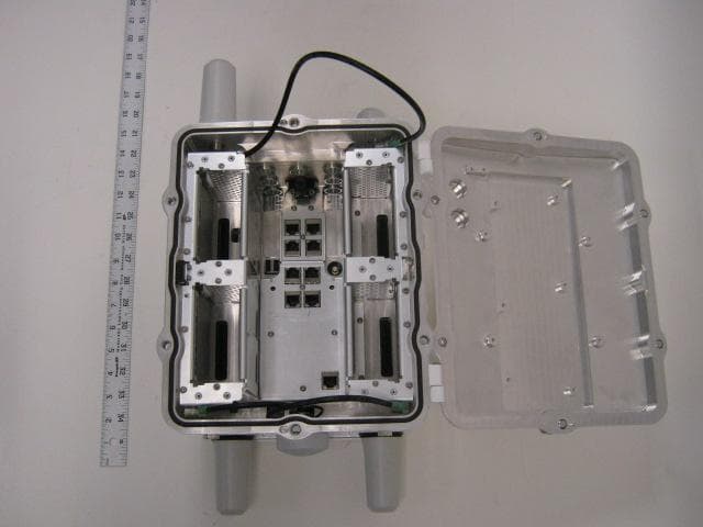
Click to zoom
Application Details
- Equipment Class
- DTS - Digital Transmission System
- Date of Grant
- Feb 02, 2012
- Application Purpose
- Original Equipment
- Date of Application
- Feb 02, 2012
- Equipment Note
- Utility Meter Monitoring System
- Frequency Range
- 2412.00000000 - 2462.00000000
- Company
- Cisco Systems Inc
- Country
- United States
Documents & Files
Document Text
Text extracted from the exhibit documents filed with the FCC. Open a document above to read the original.
Users Manual
DEC. 2011—EFT REVIEW DRAFT—CISCO CONFIDENTIAL Americas Headquarters Cisco Systems, Inc. 170 West Tasman Drive San Jose, CA 95134-1706 USA http://www.cisco.com Tel: 408 526-4000 800 553-NETS (6387) Fax: 408 527-0883 Cisco 1240 Connected Grid Router Hardware Installation Guide Text Part Number: OL-26223-01 DEC. 2011—EFT REVIEW DRAFT—CISCO CONFIDENTIAL THE SPECIFICATIONS AND INFORMATION REGARDING THE PRODUCTS IN THIS MANUAL ARE SUBJECT TO CHANGE WITHOUT NOTICE. ALL STATEMENTS, INFORMATION, AND RECOMMENDATIONS IN THIS MANUAL ARE BELIEVED TO BE ACCURATE BUT ARE PRESENTED WITHOUT WARRANTY OF ANY KIND, EXPRESS OR IMPLIED. USERS MUST TAKE FULL RESPONSIBILITY FOR THEIR APPLICATION OF ANY PRODUCTS. THE SOFTWARE LICENSE AND LIMITED WARRANTY FOR THE ACCOMPANYING PRODUCT ARE SET FORTH IN THE INFORMATION PACKET THAT SHIPPED WITH THE PRODUCT AND ARE INCORPORATED HEREIN BY THIS REFERENCE. IF YOU ARE UNABLE TO LOCATE THE SOFTWARE LICENSE OR LIMITED WARRANTY, CONTACT YOUR CISCO REPRESENTATIVE FOR A COPY. The following information is for FCC compliance of Class A devices: This equipment has been tested and found to comply with the limits for a Class A digital device, pursuant to part 15 of the FCC rules. These limits are designed to provide reasonable protection against harmful interference when the equipment is operated in a commercial environment. This equipment generates, uses, and can radiate radio-frequency energy and, if not installed and used in accordance with the instruction manual, may cause harmful interference to radio communications. Operation of this equipment in a residential area is likely to cause harmful interference, in which case users will be required to correct the interference at their own expense. The following information is for FCC compliance of Class B devices: This equipment has been tested and found to comply with the limits for a Class B digital device, pursuant to part 15 of the FCC rules. These limits are designed to provide reasonable protection against harmful interference in a residential installation. This equipment generates, uses and can radiate radio frequency energy and, if not installed and used in accordance with the instructions, may cause harmful interference to radio communications. However, there is no guarantee that interference will not occur in a particular installation. If the equipment causes interference to radio or television reception, which can be determined by turning the equipment off and on, users are encouraged to try to correct the interference by using one or more of the following measures: •Reorient or relocate the receiving antenna. •Increase the separation between the equipment and receiver. •Connect the equipment into an outlet on a circuit different from that to which the receiver is connected. •Consult the dealer or an experienced radio/TV technician for help. Modifications to this product not authorized by Cisco could void the FCC approval and negate your authority to operate the product. The Cisco implementation of TCP header compression is an adaptation of a program developed by the University of California, Berkeley (UCB) as part of UCB’s public domain version of the UNIX operating system. All rights reserved. Copyright © 1981, Regents of the University of California. NOTWITHSTANDING ANY OTHER WARRANTY HEREIN, ALL DOCUMENT FILES AND SOFTWARE OF THESE SUPPLIERS ARE PROVIDED “AS IS” WITH ALL FAULTS. CISCO AND THE ABOVE-NAMED SUPPLIERS DISCLAIM ALL WARRANTIES, EXPRESSED OR IMPLIED, INCLUDING, WITHOUT LIMITATION, THOSE OF MERCHANTABILITY, FITNESS FOR A PARTICULAR PURPOSE AND NONINFRINGEMENT OR ARISING FROM A COURSE OF DEALING, USAGE, OR TRADE PRACTICE. IN NO EVENT SHALL CISCO OR ITS SUPPLIERS BE LIABLE FOR ANY INDIRECT, SPECIAL, CONSEQUENTIAL, OR INCIDENTAL DAMAGES, INCLUDING, WITHOUT LIMITATION, LOST PROFITS OR LOSS OR DAMAGE TO DATA ARISING OUT OF THE USE OR INABILITY TO USE THIS MANUAL, EVEN IF CISCO OR ITS SUPPLIERS HAVE BEEN ADVISED OF THE POSSIBILITY OF SUCH DAMAGES. CCDE, CCENT, Cisco Eos, Cisco HealthPresence, the Cisco logo, Cisco Lumin, Cisco Nexus, Cisco StadiumVision, Cisco TelePresence, Cisco WebEx, DCE, and Welcome to the Human Network are trademarks; Changing the Way We Work, Live, Play, and Learn and Cisco Store are service marks; and Access Registrar, Aironet, AsyncOS, Bringing the Meeting To You, Catalyst, CCDA, CCDP, CCIE, CCIP, CCNA, CCNP, CCSP, CCVP, Cisco, the Cisco Certified Internetwork Expert logo, Cisco IOS, Cisco Press, Cisco Systems, Cisco Systems Capital, the Cisco Systems logo, Cisco Unity, Collaboration Without Limitation, EtherFast, EtherSwitch, Event Center, Fast Step, Follow Me Browsing, FormShare, GigaDrive, HomeLink, Internet Quotient, IOS, iPhone, iQuick Study, IronPort, the IronPort logo, LightStream, Linksys, MediaTone, MeetingPlace, MeetingPlace Chime Sound, MGX, Networkers, Networking Academy, Network Registrar, PCNow, PIX, PowerPanels, ProConnect, ScriptShare, SenderBase, SMARTnet, Spectrum Expert, StackWise, The Fastest Way to Increase Your Internet Quotient, TransPath, WebEx, and the WebEx logo are registered trademarks of Cisco Systems, Inc. and/or its affiliates in the United States and certain other countries. All other trademarks mentioned in this document or website are the property of their respective owners. The use of the word partner does not imply a partnership relationship between Cisco and any other company. (0812R) No combinations are authorized or intended under this document. Any Internet Protocol (IP) addresses and phone numbers used in this document are not intended to be actual addresses and phone numbers. Any examples, command display output, network topology diagrams, and other figures included in the document are shown for illustrative purposes only. Any use of actual IP addresses or phone numbers in illustrative content is unintentional and coincidental. © 2012 Cisco Systems, Inc. All rights reserved. DEC. 2011—EFT REVIEW DRAFT—CISCO CONFIDENTIAL Contents iii Cisco 1240 Conne…
Text truncated - open the document above for the full version.
Users Manual
Americas Headquarters: Cisco Systems, Inc., 170 West Tasman Drive, San Jose, CA 95134-1706 USA Cisco Connected Grid 3G Module Installation and Configuration Guide First Published: January, 2012 Part Number: OL-25991-01 This document provides an overview of hardware and configuration information for the following single-wide grid router WAN interface card modules: •Cisco Connected Grid Module—3G EVDO Rev A/0/1xRTT (CDMA version) •Cisco Connected Grid Module—3G HSPA+/UMTS/GSM/GPRS/EDGE (GSM version) These 3rd Generation technology modules are supported on Cisco 1240 Connected Grid Router. This document contains the following topics: •Kit Contents, page 2 •Features, page 4 •Hardware Overview, page 5 •Installing and Removing the SIM Card (GSM Module), page 17 •Installing and Removing the 3G Module, page 18 •Regulatory and Compliance Information, page 21 •Software Overview, page 21 •Configuring the Module, page 24 •Configuration Example, page 33 •Debug Commands, page 38 •Additional References, page 36 •Technical Assistance, page 37 •Troubleshooting and Diagnostics, page 38 WarningOnly trained and qualified personnel should be allowed to install, replace, or service this equipment. Statement 1030 2 Cisco Connected Grid 3G Module Installation and Configuration Guide OL-25991-01 Kit Contents NoteThe Cisco Connected Grid 3G Module is installed in the router at the factory. Only Cisco Systems or Itron, Inc. technicians may install, uninstall, or configure Connected Grid Modules. Figure 1Cisco Connected Grid 2G/3G Wireless Connected Grid Module Kit Contents Your 3G module kit contains the GSM or CDMA module. Parts can be ordered by referencing the following information shown in Ta b l e 1. 284021 Table 1Kit Contents for the 3G Module Cisco Part NumberModeDescriptionFrequency Band CGM-3G-EVDO-VCDMA/EVDOConnected Grid Module - 3G Verizon EVDO Rev A/0/1xRTT •800 MHz: North American cellular band •1900 MHz: North American PCS band CGM-3G-EVDO-SCDMA/EVDOConnected Grid Module - 3G Sprint EVDO Rev A/0/1xRTT •800 MHz: North American cellular band •1900 MHz: North American PCS band 3 Cisco Connected Grid 3G Module Installation and Configuration Guide OL-25991-01 Kit Contents For system requirements, important notes, limitations, open and resolved bugs, and last-minute documentation updates, see the Release Notes on Cisco.com. For translations of the warnings that appear in this document, see the Regulatory Compliance and Safety Information document for your router on Cisco.com. When using the online publications, see the documents that match the Cisco system software version run- ning on the 2G/3G wireless module. CGM-3G-HSPA-AGSM/HSPA+Connected Grid Module - 3G AT&T HSPA+/UMTS/ GSM/GPRS/EDGE •GSM: 850, 900, 1900 MHz. •WCDMA/UMTS/HSPA+: 850, 900, 1800, 1900, 2100 MHz. CGM-3G-HSPA-GGSM/HSPA+Connected Grid Module - 3G (Global) HSPA+/UMTS/ GSM/GPRS/EDGE •GSM: 850, 900, 1900 MHz. •WCDMA/UMTS/HSPA+: 850, 900, 1800, 1900, 2100 MHz. Table 1Kit Contents for the 3G Module Cisco Part NumberModeDescriptionFrequency Band 4 Cisco Connected Grid 3G Module Installation and Configuration Guide OL-25991-01 Features Features Cisco Connected Grid 3G GSM Modules offer the following features: The Cisco Connected Grid 3G GSM and CDMA modules share the following key features: •Supported on the Cisco 1240 Connected Grid Router and the Cisco 1120 Connected Grid Router •Supports Cisco system software •Provides the primary cellular WAN connection for critical data applications in supporting the Connected-Grid Router •WAN connectivity as a backup data link for critical data applications •USB interface—Data, control, and diagnostics channels; control, bulk, and interrupt transfers; low (1.1 Mbps), full (12 Mbps), and high (480 Mbps) speeds •SIM plug-in SIM card—USB, ISO 7816 compliant, (U)SAT commands, USIM, 3G phone book, flash memory 8/6/128-1024 MB Table 2Feature Information for 3G module 3G GSM Module3G CDMA Module •MC8705 PCI Express Mini Card wireless data modem: –GSM data connectivity –GSM SIM-card interface –USB 2.0 high-speed (480 Mbps) interface for data and management traffic –Supports 850 MHz, 900 MHz, 1800 MHz, and 1900 MHz frequencies –PCI Express chip-set interface –Input/output hub component for embedded applications •MC5728V PCI Express Mini Card wireless data modem: –CDMA data connectivity –1xEVDO data connectivity (full-mini and half-mini) –USB 2.0 high-speed (480 Mbps) interface for data and management traffic –Supports 800 MHz, 850 MHz, 900 MHz, 1900 MHz, and 2100 MHz frequencies –PCI Express chip-set interface –Input/output hub component for embedded applications •Support for the following technologies: –High Speed Packet Access (HSPA and HSPA+) –High-speed Downlink Packet Access (HSDPA) –High-speed Uplink Packet Access (HSUPA) –Universal Mobile Telecommunication System (UMTS) –Enhanced Data-Rates for GSM Evolution (EDGE) –General Packet Radio Service (GPRS) •Support for the following technologies: –EVDO Rev. A –EVDO Rel. 0 –1xRTT 5 Cisco Connected Grid 3G Module Installation and Configuration Guide OL-25991-01 Hardware Overview 3G module provides the following functionality: •Broadband WAN connectivity using high-speed cellular data technology •Automatic best-network selection •Always-on capability •Multiple antenna and cable options: –Diversity antenna –Indoor and outdoor external antennas –Radio Frequency Ultra-Low Loss (RF-ULL) cable •Dynamic IP addressing •Cellular modem upgrade over wireless link •Modem management—Enables you to access modem software and hardware information, radio and network status, and data profile information by using Cisco commands. •Auto-detect—3G WAN for fixed and modular routers automatically detects and uses the best available service. •Profile Configuration—Enables you to configure the Access-Point Name (APN) profile. •Firmware upgrade—Enables you to upgrade the firmware on the modem by using Cisco commands. •3G wireless WAN for fixed and modular routers support on Cisco Connected …
Text truncated - open the document above for the full version.
Users Manual
FIRST REVIEW DRAFT—CISCO CONFIDENTIAL Americas Headquarters: Cisco Systems, Inc., 170 West Tasman Drive, San Jose, CA 95134-1706 USA Cisco Connected Grid WPAN Module for CGR1000 Series Installation and Configuration Guide First Published: January, 2012 OL-26243-01 This guide explains how to install the Wireless Personal Area Network (WPAN) module, as well as how to configure the Cell Relay (release 3.7). This document contains the following topics: •Kit Contents, page 2 •Features, page 2 •Hardware Overview, page 2 •Installing and Removing the Module, page 6 •Regulatory and Compliance Information, page 8 •Software Overview, page 8 •Additional References, page 17 •Technical Assistance, page 18 WarningOnly trained and qualified personnel should be allowed to install, replace, or service this equipment. Statement 1030 NoteThe Cisco Connected Grid WPAN Module is installed in the router at the factory. Only Cisco Systems or Itron, Inc. technicians may install, uninstall, or configure Connected Grid Modules. FIRST REVIEW DRAFT—CISCO CONFIDENTIAL 2 Cisco Connected Grid WPAN Module for CGR1000 Series Installation and Configuration Guide OL-26243-01 Kit Contents Figure 1Cisco Connected Grid WPAN Module Kit Contents For system requirements, important notes, limitations, open and resolved bugs, and last-minute documentation updates, see the Release Notes on Cisco.com. For translations of the warnings that appear in this document, see the Regulatory Compliance and Safety Information document for your router on Cisco.com. When using the online publications, see the documents that match the Cisco system software version running on the WPAN module. Features The WPAN module provides the following functionality: •Acts as bridge between the WPAN port manager and the radio module via the Cisco Connected Grid 1240 Router's FPGA module •Monitors the health and of the WPAN module •Resets and reprograms the WPAN module •Collects statistics and status of the WPAN module Hardware Overview The WPAN module hardware is based on Itron’s Trifecta Communications Module, which contains a Cortex-M3, microcontroller, Texas Instruments CC1101 RF Transceiver operating in the 900 MHz ISM band, Semtech SX1781 PLL Frequency Synthesizer, and RF Micro Devices RF6559 front-end module. This section covers the following topics: FIRST REVIEW DRAFT—CISCO CONFIDENTIAL 3 Cisco Connected Grid WPAN Module for CGR1000 Series Installation and Configuration Guide OL-26243-01 Hardware Overview •Front Panel, page 3 •LED, page 3 •Supported Cisco Antenna, page 4 •Cisco Supported Cables, page 4 •Configuration, page 5 •Default Parameters, page 5 •Environmental Specifications, page 6 •Power Specifications, page 6 Front Panel Figure 2 shows the front panel of the WPAN module. Figure 2Front Panel of the Cisco Connected Grid WPAN Module LED Ta b le 1 lists the LED indicastor and describes the behavior. The LED provides a visual indicator of the available services. Ta b l e 1LED Indicator LED NameColorDescription StatusGreenIndicates the RF status: •Off: Module is not powered •On: System is functional - RF mesh interface is up (if installed) •Blinking: Hardware is functional - RF mesh interface is up (if installed) FIRST REVIEW DRAFT—CISCO CONFIDENTIAL 4 Cisco Connected Grid WPAN Module for CGR1000 Series Installation and Configuration Guide OL-26243-01 Hardware Overview Supported Cisco Antenna The antenna is connected to the TNC, panel-mount, 50 Ohm connector located on the faceplate of the WPAN module. For more information about antennas, including installation steps, see the Cisco Connected Grid 1240 Router Installation Guide. Ta b le 2 lists the Cisco antenna this is supported for use with the WPAN module and the Cisco Connected Grid 1120 Router. Cisco Supported Cables Ta b le 3 lists the external cable options, and internal cable/adapter available from Cisco for use with the WPAN module. Interfaces The WPAN module includes the following physical interfaces to the host: •Single RF Transceiver—supports IEEE 802.15.4g in the 915 MHz ISM. The RF transceiver is used to provide mesh networking connectivity. •Single Serial UART—used to communicate with the Cisco Connected Grid 1240 Router host processor via the onboard FPGA I/O module, providing framing control and buffering for UART data communications. •GPIO—control and data communications Ta b l e 2CGR 1240 Supported Antennas and Cables for use with the WPAN Module DescriptionOutdoor CableAntenna •WPAN Module •10.5’or 17.5’ cable through conduit Single cable passes thru conduit from inside to outside bldg. 900 MHz, 3G, 806-960 MHz, 1710-2700 MHz, Monopole Antenna, Chassis Mounted, Omni-directional, ANT-MP-INT-OUT-M, qty 1 Table 3Cisco External and Internal Cables for WPAN Module External Cable OptionsInternal Cable/AdapterAntenna Options •LMR-400-DB, 20’ CAB-L400-20-N-N •LMR-600B-DB, 30’ CAB-L600-30-N-N •LMR-100, 10.5” CAB-L100-10-Q-M, qty 1 •LMR-100-17.5” CAB-L100-17-Q-M, qty 1 •N Bulkhead adapters plus lightning arrestors, qty 2 900 MHz ISM Band, Omni Stick, ANT-RF-OMNI-OUT-N, qty 1 FIRST REVIEW DRAFT—CISCO CONFIDENTIAL 5 Cisco Connected Grid WPAN Module for CGR1000 Series Installation and Configuration Guide OL-26243-01 Hardware Overview Configuration The configuration parameters are set by the Connected Grid Network Management System (CG-NMS), through a series of CLI commands. Statistics on netork traffic is also retrieved from the interface via the RF port manager, through the use of the CLI. Default Parameters Ta b le 4 lists the interface default values. Ta b le 5 lists the default frequencies for each channel. Ta b l e 4List of Interface Default Values ParametersDefault Value Admin StateEnabled 802.14.4 Raw Data Rates155 kbps (78.6 kbps with FEC on by default) RF Transmit Power28 dBm Channels52 (frequency hopping) Link Retransmission Retries16 Mac Backoff Timer Ta b l e 5List of Default Frequencies for each Channel Channel # Channel f. (MHz)Channel # Channel f. (MHz)Channel # Channel f. (MHz)…
Text truncated - open the document above for the full version.
Users Manual
DEC. 2011—EFT REVIEW DRAFT—CISCO CONFIDENTIAL 6-9 Cisco 1240 Connected Grid Router Hardware Installation Guide OL-26223-01 Chapter 6 Installing the Router Basic Hardware Installation Use the show interface Command To verify that the router has been successfully installed and connected to the network, use the show interface command to confirm that the router Ethernet interface is up. CGR1240> show interface Ethernet0 is up, line protocol is up Hardware is Cisco, address is 0019.076c.1a78 (bia 0019.076c.1a78) Internet address is 192.0.2.111/23 MTU 1500 bytes, BW 10000 Kbit, DLY 1000 usec, rely 255/255, load 1/255 Encapsulation ARPA, loopback not set, keepalive set (10 sec) ARP type: ARPA, ARP Timeout 04:00:00 Last input 00:00:00, output 00:00:00, output hang never Last clearing of "show interface" counters never Queueing strategy: fifo Output queue 0/40, 0 drops; input queue 5/75, 32 drops 5 minute input rate 10000 bits/sec, 27 packets/sec 5 minute output rate 10000 bits/sec, 26 packets/sec 16076431 packets input, 1280716531 bytes, 27 no buffer Received 1809290 broadcasts, 0 runts, 0 giants 1105 input errors, 0 CRC, 0 frame, 0 overrun, 1105 ignored, 0 abort 0 input packets with dribble condition detected 16196175 packets output, 1011044938 bytes, 0 underruns 19 output errors, 184 collisions, 3 interface resets 0 babbles, 0 late collision, 1474 deferred 19 lost carrier, 0 no carrier 0 output buffer failures, 0 output buffers swapped out Serial0 is administratively down, line protocol is down Hardware is HD64570 MTU 1500 bytes, BW 1544 Kbit, DLY 20000 usec, rely 255/255, load 1/255 Encapsulation HDLC, loopback not set, keepalive set (10 sec) Last input never, output never, output hang never Last clearing of "show interface" counters never Input queue: 0/75/0 (size/max/drops); Total output drops: 0 Queueing strategy: weighted fair Output queue: 0/64/0 (size/threshold/drops) Conversations 0/0 (active/max active) Reserved Conversations 0/0 (allocated/max allocated) 5 minute input rate 0 bits/sec, 0 packets/sec 5 minute output rate 0 bits/sec, 0 packets/sec 0 packets input, 0 bytes, 0 no buffer Received 0 broadcasts, 0 runts, 0 giants 0 input errors, 0 CRC, 0 frame, 0 overrun, 0 ignored, 0 abort 0 packets output, 0 bytes, 0 underruns 0 output errors, 0 collisions, 1 interface resets 0 output buffer failures, 0 output buffers swapped out 0 carrier transitions DCD=down DSR=down DTR=down RTS=down CTS=down For more information about using the show interface command, see the Cisco 1000 Series Connected Grid Routers Software Configuration Guide. DEC. 2011—EFT REVIEW DRAFT—CISCO CONFIDENTIAL 6-10 Cisco 1240 Connected Grid Router Hardware Installation Guide OL-26223-01 Chapter 6 Installing the Router Additional Router Connections Additional Router Connections This section provides information about making other, additional router cable connections. Follow the procedures in this section based on your network configuration and requirements. This section contains these procedures: •External Connections and Chassis Cable Ports, page 6-10 •Using Cable Glands, page 6-11 •Connecting the Console Port, page 6-15 •Connecting the Serial Port, page 6-16 •Connecting the USB Ports, page 6-17 •Connecting the SFP Ports, page 6-18 •Connecting the Ethernet Ports, page 6-20 •Connecting the Alarm Port, page 6-22 •Connecting the IRIG-B Port, page 6-23 External Connections and Chassis Cable Ports When connecting the router internal ports to external cables or exterior devices, you must thread the router cables through the chassis cable ports designated for this purpose. Some chassis ports are reserved for specific cables and remaining ports can be used based on your network configuration and cabling requirements. There are nine cable ports on the chassis base and two ports on the chassis door (Figure 6-8). Some ports are reserved for a specific cables types, as indicated Figure 6-8. CautionWhen you make router cable connections through these ports, you must use cable glands as described in Using Cable Glands, page 6-11, to protect the router interior from environmental elements, including moisture, heat, cold, and dust. Failure to use cable glands with the chassis cable ports can result in damage to the router. DEC. 2011—EFT REVIEW DRAFT—CISCO CONFIDENTIAL 6-11 Cisco 1240 Connected Grid Router Hardware Installation Guide OL-26223-01 Chapter 6 Installing the Router Additional Router Connections Figure 6-8Chassis Cable Ports—For Cabling to External Connectors or Devices Using Cable Glands This section describes how to use cable glands with router cables that are threaded through the chassis cable ports that are described in External Connections and Chassis Cable Ports, page 6-10. CautionThe cable glands must be used for all cables that are threaded through the router chassis cable ports to prevent exposing the router interior to environmental elements. Ordering Cisco Cable Glands You can order a cable gland kit from Cisco using the model number CGR-IP67GLAND. Each kit contains one cable gland. See the chapter Router Hardware Description for detailed information about this part. Tools You Supply You must supply a 13-mm box-end wrench or socket set to install the cable glands on the router. ItemDescriptionItemDescription 1These two ports on the router base are reserved for SPF module cables. One of these ports is shown with the liquid tight seal that must be used when the port is not in use. 2These two ports on the router door are reserved for non-Cisco module cables. 112 DEC. 2011—EFT REVIEW DRAFT—CISCO CONFIDENTIAL 6-12 Cisco 1240 Connected Grid Router Hardware Installation Guide OL-26223-01 Chapter 6 Installing the Router Additional Router Connections Cable Glands Description Figure 6-9Cable Glands, Assembled Figure 6-10Cable Gland Components ItemNameDescription 1AdapterConnects directly to the chassis cable port on the router. 2GrommetSecures the split gasket over the cable 3Split gasketFits over the cable and creates an liq…
Text truncated - open the document above for the full version.
Cover Letter(s)
Cisco Systems, Inc. 170 West Tasman Drive San Jose, CA 95134-1706 Phone 408 526-4000 Fax: 408 526 –4100 http://www.cisco.com February 3, 2012 Federal Communications Commission Office of Engineering and Technology Equipment Authorization division 7345 Oakland Mills Road Columbia, Maryland 21046 Subject: Confidentiality request for FCC ID LDKALTMT0556 Pursuant to FCC 47 CRF 0.457(d) and 0.459 and IC RSP-100, Section 10, the applicant requests that a part of the subject FCC application be held confidential. Type of Confidentiality Requested Exhibit Short Term Permanent Block Diagrams Short Term External Photos Short Term Permanent* 1 Internal Photos Short Term Permanent Operation Description/Theory of Operation Short Term Permanent Parts List & Placement/BOM Short Term Permanent Tune-Up Procedure Short Term Permanent Schematics Short Term Test Setup Photos Short Term Permanent* User’s Manual Permanent Confidentiality: The applicant requests the exhibits listed above as permanently confidential be permanently withheld from public review due to materials that contain trade secrets and proprietary information not customarily released to the public. Short-Term Confidentiality: The applicant requests the exhibits selected above as short term confidential be withheld from public view for a period of _45 days from the date of the Grant of Equipment Authorization and prior to marketing. This is to avoid premature release of sensitive information prior to marketing or release of the product to the public. Applicant is also aware that they are responsible to notify ACB in the event information regarding the product or the product is made available to the public. ACB will then release the documents listed above for public disclosure pursuant to FCC Public Notice DA 04-1705. Sincerely, Gerard Thorpe MANAGER.HARDWARE ENGINEERING Cisco Systems, Inc.
External Photos
Cisco Systems, Inc. 170 West Tasman Drive San Jose, CA 95134-1706 Phone 408 526-4000 Fax: 408 526 –4100 http://www.cisco.com Exhibit : External Photos Model: Cisco CGR 1240 FCC ID: LDKALTMT0556 IC ID: 2461B-ALTMT0556 CGR-1240 : Interior CGR-1240 : Bottom chassis CGR-1240 : TOP CGR-1240 : Front Side CGR-1240 : Side CGR-1240 : Back side
ID Label/Location Info
EDCS-1118879 Cisco Systems, Inc. 170 West Tasman Drive San Jose, CA 95134-1706 Phone 408 526-4000 Fax: 408 526 –4100 http://www.cisco.com Exhibit : Label Location Model: CGR1240 FCC ID: LDKALTMT0556 IC ID: 2461B-ALTMT0556 The label on the right is the Compliance label, the one on the left is the one that has all the IDs for the modules and the FCC / IC .
ID Label/Location Info
Dimensions are shown in imperial (metric) Tolerances unless otherwise specified are: Dimensions Tolerance: P2C Tolerance: ± 0.010” ± 0.010” SCALE:1:1 SHEET:1 of 1 UNIT: INCHES ORIGINATIONDATECHECK BYDATE Rev.DescriptionECN Angie R. WM REF. No. Red Line is cut line LABEL FINISHED COPY: NOTES: A) Material Worldmark 3361T-J1 Mat Ref: Laminate: Adhesive: LABELS/TILE: TILES/PACK: LABELS/PACK: Matrix Strip:YN B) COLORSC) FONTS 1)1) 2) 2) 3) 4) 5) 6) 7) 8) 3) 4) 5) 6) 7) 8) White Background Black Graphics 2.200” .200” PEEL TAB 1.400” 1.600” .100” R. 4x DWG/PART No:47-24707-01 Rev. 01 ARTWORK No:56-18701-01 Rev. 01 CUST. NAME: Artwork Proof #: 4 11-21-11 Title:________________________________Date:______________ Approved By:___________________________________________ DELIVERY TIME CAN ONLY BE MET WITH YOUR COOPERATION. PLEASE ENSURE THE ARTWORK PROOF IS CHECKED CAREFULLY FOR LAYOUT, WORDING, SPELLING, SIZE, COLOR, ETC., THEN, RETURNED WITHIN 24 HOURS, TO ENSURE DELIVERY SCHEDULES ARE MET. THE COLORS DISPLAYED ON THIS PROOF MAY NOT BE ACCURATE; REFER TO PMS OR CISCO COLOR BOOK REFERENCES STATED FOR TRUE REPRESENTATION. IMPORTANT KCC-CMM-TNY-CGR1240 CGR1240 See Manual before Use Watertight IP67, Type 4 Enclosure 47-24707-01 Rev. 01 DPC This Cisco 1240 Series Router may be connected to the Telecom Network PCT232/10/04 TELEPERMIT I.T .E. 4TØ2
Internal Photos
EDCS-1118876 Cisco Systems, Inc. 170 West Tasman Drive San Jose, CA 95134-1706 Phone 408 526-4000 Fax: 408 526 –4100 http://www.cisco.com Exhibit : Internal Photos Model: Cisco CGR 1240 FCC ID: LDKALTMT0556 IC ID: 2461B-ALTMT0556 CGR-1240 : Internal PCB Mother Board (Bottom) CGR-1240 : Internal PCB Mother Board (Top) EDCS-1118876 Cisco Systems, Inc. 170 West Tasman Drive San Jose, CA 95134-1706 Phone 408 526-4000 Fax: 408 526 –4100 http://www.cisco.com Exhibit : Internal Photos Model: CGR1240 FCC ID: LDKALTMT0556 IC ID: 2461B-ALTMT0556 CGR1240 : Internal PCB Mother Board (Bottom) CGR1240 : Internal PCB Mother Board (Top) CGR1240 : Internal PCB Daughter card (Top) CGR1240 : Internal PCB Daughter card (Bottom) CGR1240 : 2400MHz DTS transmitter section close up CGR1240 : 2400MHz DTS transmitter connector and Antenna 2400MHz DTS Tx connector & Antenna assembly
RF Exposure Info
RF Exposure Study - Engineering Analysis per FCC 2.1093 Industry Canada RSS-102 CGR1240 FCC ID : LDKALTMT0556 IC : 2461B-ALTMT0556 Supplementary Appendix to Report EDCS# 1104807 Prepared By: Cisco Systems Inc 170 West Tasman San Jose, CA 95134 USA 1.0: Attestation Statement of Compliance The Cisco Systems CGR1240 with modules have been evaluated for Maximum Permissible Exposure in compliance with 47 Code of Federal Regulations 2.1093. The evaluation was in accordance with methodology as referenced in FCC Bulletin OET 65C (rev 01-01) by Compliance Certification Services This report serves as the additional technical analysis of the Cisco radio modules This study addresses the addition of an additional pair of transmitters using the data derived in the afore mentioned report # 1104807. The limits used for this evaluation are in line with the recommendations of the World Health Organizations (WHO) International Committee on Non Ionizing Radiation Protection (ICNIRP) as well as the American National Standards Institute (ANSI) C95.1. The limits chosen are of General Population/Uncontrolled Exposure. The device is pole mounted. The device is high enough that it is not accessible by the general …
Text truncated - open the document above for the full version.
Contact Information
Applicant
Samuel Kim(Manager, Engineering)
Technical Contact
Cisco SystemsJose Luis Aguirre
[email protected]408-525-0835
125 West Tasman Drive · San Jose · United States
Non-Technical Contact
Cisco SystemsShyam Pullela
[email protected]408-527-1701
Test Firm
Cisco Systems, Inc.Dave Wilson
Technical Specifications
| # | Rule Parts | Frequency Range | Power Output |
|---|---|---|---|
| 1 | 15C | 2.41 GHz - 2.46 GHz | 13.40 mW |
Other Applications from Cisco Systems Inc

LDKJ98213058
May 25, 2026Wireless Phone
Equipment Class
DSS - Part 15 Spread Spectrum TransmitterLDKIW9165E
Aug 20, 2024Wi-Fi 6E Outdoor Access Point
Equipment Class
6SD - 15E 6 GHz Standard Power Access PointLDKIW9165DH
Aug 05, 2024Wi-Fi 6E Outdoor Access Point
Equipment Class
6SD - 15E 6 GHz Standard Power Access PointLDKUSBC2857
Jul 22, 2024Cisco Headset USB-C Adapter
Equipment Class
DSS - Part 15 Spread Spectrum TransmitterLDKESPRD2922
May 09, 2024UC Phone
Equipment Class
NII - Unlicensed National Information Infrastructure TX