LDKCALAB0676Cisco 1120 Connected Grid Router (CGR 1120)
Cisco Systems Inc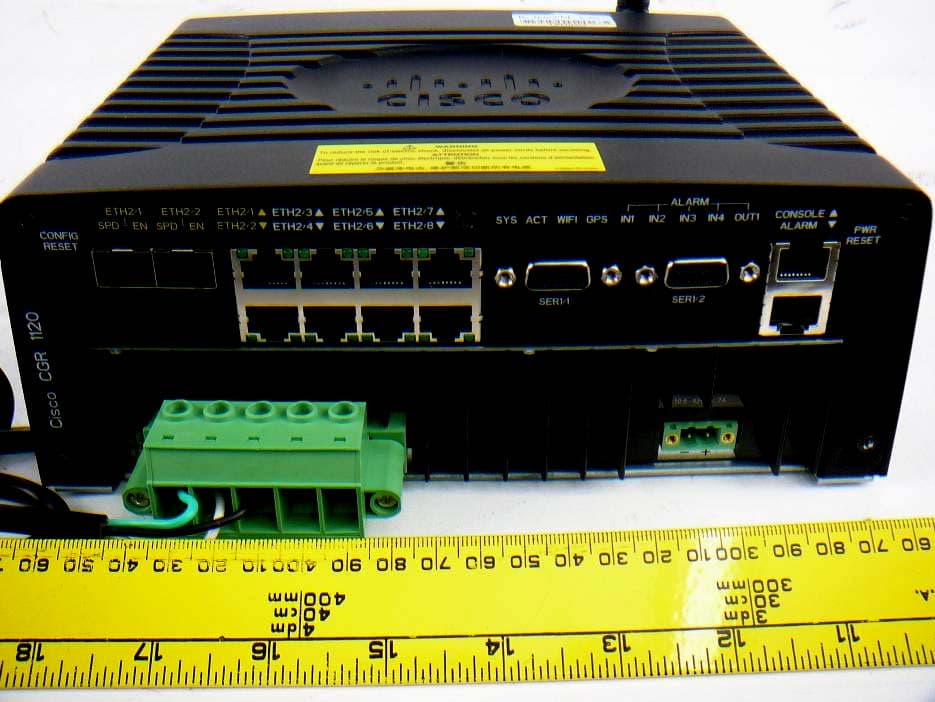
Click to zoom
Application Details
- Equipment Class
- DTS - Digital Transmission System
- Date of Grant
- Nov 29, 2012
- Application Purpose
- Original Equipment
- Date of Application
- Nov 29, 2012
- Equipment Note
- Cisco 1120 Connected Grid Router (CGR 1120)
- Frequency Range
- 2412.00000000 - 2462.00000000
- Company
- Cisco Systems Inc
- Country
- United States
Documents & Files
Document Text
Text extracted from the exhibit documents filed with the FCC. Open a document above to read the original.
Users Manual
Americas Headquarters Cisco Systems, Inc. 170 West Tasman Drive San Jose, CA 95134-1706 USA http://www.cisco.com Tel: 408 526-4000 800 553-NETS (6387) Fax: 408 527-0883 Cisco 1120 Connected Grid Router Hardware Installation Guide Last updated: November 26, 2012 Text Part Number: OL-26438-01 THE SPECIFICATIONS AND INFORMATION REGARDING THE PRODUCTS IN THIS MANUAL ARE SUBJECT TO CHANGE WITHOUT NOTICE. ALL STATEMENTS, INFORMATION, AND RECOMMENDATIONS IN THIS MANUAL ARE BELIEVED TO BE ACCURATE BUT ARE PRESENTED WITHOUT WARRANTY OF ANY KIND, EXPRESS OR IMPLIED. USERS MUST TAKE FULL RESPONSIBILITY FOR THEIR APPLICATION OF ANY PRODUCTS. THE SOFTWARE LICENSE AND LIMITED WARRANTY FOR THE ACCOMPANYING PRODUCT ARE SET FORTH IN THE INFORMATION PACKET THAT SHIPPED WITH THE PRODUCT AND ARE INCORPORATED HEREIN BY THIS REFERENCE. IF YOU ARE UNABLE TO LOCATE THE SOFTWARE LICENSE OR LIMITED WARRANTY, CONTACT YOUR CISCO REPRESENTATIVE FOR A COPY. The Cisco implementation of TCP header compression is an adaptation of a program developed by the University of California, Berkeley (UCB) as part of UCB’s public domain version of the UNIX operating system. All rights reserved. Copyright © 1981, Regents of the University of California. NOTWITHSTANDING ANY OTHER WARRANTY HEREIN, ALL DOCUMENT FILES AND SOFTWARE OF THESE SUPPLIERS ARE PROVIDED “AS IS” WITH ALL FAULTS. CISCO AND THE ABOVE-NAMED SUPPLIERS DISCLAIM ALL WARRANTIES, EXPRESSED OR IMPLIED, INCLUDING, WITHOUT LIMITATION, THOSE OF MERCHANTABILITY, FITNESS FOR A PARTICULAR PURPOSE AND NONINFRINGEMENT OR ARISING FROM A COURSE OF DEALING, USAGE, OR TRADE PRACTICE. IN NO EVENT SHALL CISCO OR ITS SUPPLIERS BE LIABLE FOR ANY INDIRECT, SPECIAL, CONSEQUENTIAL, OR INCIDENTAL DAMAGES, INCLUDING, WITHOUT LIMITATION, LOST PROFITS OR LOSS OR DAMAGE TO DATA ARISING OUT OF THE USE OR INABILITY TO USE THIS MANUAL, EVEN IF CISCO OR ITS SUPPLIERS HAVE BEEN ADVISED OF THE POSSIBILITY OF SUCH DAMAGES.Cisco and the Cisco logo are trademarks or registered trademarks of Cisco and/or its affiliates in the U.S. and other countries. To view a list of Cisco trademarks, go to this URL: www.cisco.com/go/trademarks. Third-party trademarks mentioned are the property of their respective owners. The use of the word partner does not imply a partnership relationship between Cisco and any other company. (1110R) No combinations are authorized or intended under this document. Any Internet Protocol (IP) addresses used in this document are not intended to be actual addresses. Any examples, command display output, and figures included in the document are shown for illustrative purposes only. Any use of actual IP addresses in illustrative content is unintentional and coincidental. Cisco 1120 Connected Grid Router Hardware Installation Guide ©2012 Cisco Systems, Inc. All rights reserved. Contents iii Cisco 1120 Connected Grid Router Hardware Installation Guide OL-26438-01 CONTENTS CHAPTER 1Unpacking the Router1-1 Unpacking the Router1-1 Router Package Contents1-2 CHAPTER 2Installation Safety and Site Preparation2-1 Safety Recommendations2-2 Safety with Electricity2-3 Preventing Electrostatic Discharge Damage2-3 General Site Requirements2-4 Rack Mounting2-4 Router Environmental Requirements2-4 Power Guidelines and Requirements2-4 Network Cabling Specifications2-5 Preparing for Network Connections2-5 Ethernet Connections2-5 Serial Connections2-5 Required Tools and Equipment for Installation and Maintenance2-7 CHAPTER 3Router Hardware Description3-1 Router Overview3-1 Applications Overview3-1 Hardware Compliance3-2 Router Hardware Overview3-2 Hardware Features3-4 Chassis3-4 Mounting Features3-5 Mounting Procedures3-6 Module Panel (Front Panel) Features3-6 Front Panel LEDs3-7 WiFi Antenna Port3-7 USB Port3-8 SD Flash Memory Module3-8 GPS Antenna Port3-9 Kensington-Compatible Security Slot3-9 Connected Grid Module Slots3-10 Cable Panel (Back Panel) Features3-11 Contents iv Cisco 1120 Connected Grid Router Hardware Installation Guide OL-26438-01 Back Panel LEDs3-12 CONFIG Reset Button3-12 PWR RESET Button3-12 Small Form-Factor Pluggable (SFP) Ports3-12 Ethernet Ports3-13 Combo Ports3-15 Serial Ports3-15 Console Port3-16 AC Power Supply3-17 DC Input for Battery Backup3-17 Power Specifications3-17 Alarm Port3-18 Internal Hardware Features3-19 Memory3-19 Internal GPS Module3-19 Short-Range Access Point3-20 Real-Time Clock (RTC)3-21 Temperature Sensor3-21 CHAPTER 4Mounting the Router4-1 Router Mounting Kit4-1 Mounting Kit Contents4-1 Prepare to Mount the Router4-2 Materials and Tools You Supply4-3 Router Orientation When Mounting4-3 General Safety Information for Mounting4-3 Mounting Instructions4-4 Attach the Mounting Bracket to the Router4-4 Mount the Router on a DIN Rail4-6 Mount the Router on a Wall4-7 Ground the Router4-8 CHAPTER 5Connecting the Router to Power5-1 Before You Begin5-1 Verify Router Hardware Readiness5-1 Tools and Materials You Supply5-2 EMC Class A Notices and Warnings (US and Canada)5-2 Class A Notice for FCC5-2 Class A Notice for Canada5-3 Contents v Cisco 1120 Connected Grid Router Hardware Installation Guide OL-26438-01 Safety Information5-3 AC Power Connection Information5-4 Router Power Source Input Terminals5-4 Electrical Wire Color Codes5-5 Terminal Blocks and Mating Connectors for Power Input Wiring5-6 Connect to AC Power5-7 Verify AC Power Connection5-9 Connect to DC Power (Optional)5-9 Power Cycling the Router5-10 Accessing the Buttons5-10 CHAPTER 6Making Network Connections6-1 Before Installing6-1 Installation Site Preparation6-1 Installation Safety Information6-2 Connecting the Router to Power6-2 Preventing Electrostatic Discharge Damage6-2 Cabling Guidelines6-2 Basic Network Connections6-2 Connect to the Ethernet Network6-3 Connecting the Ethernet Ports6-3 Connecting the SFP Ports6-4 Verify Ethernet Connection with System Software CLI6-6 Additional Router Connections6-7 Connecting the Console Port6-8 About6-8 Connecting6-8 Related Information6-9 Connecting the Serial Port6-9 …
Text truncated - open the document above for the full version.
External Photos
Cisco Systems, Inc. FCC ID: LDKCALAB0676, IC: 2461B-CALAB0676 Report Number: R1210294-247 Page 64 of 70 FCC Part 15C/IC RSS-210 Test Report 16 Exhibit C – EUT Photographs 16.1 EUT – Top View 16.2 EUT – Front View Cisco Systems, Inc. FCC ID: LDKCALAB0676, IC: 2461B-CALAB0676 Report Number: R1210294-247 Page 65 of 70 FCC Part 15C/IC RSS-210 Test Report 16.3 EUT – Left Side View 16.4 EUT – Right Side View Cisco Systems, Inc. FCC ID: LDKCALAB0676, IC: 2461B-CALAB0676 Report Number: R1210294-247 Page 66 of 70 FCC Part 15C/IC RSS-210 Test Report 16.5 EUT – Rear Side View (With Antenna) 16.6 EUT – Rear Side View (Without Antenna) Cisco Systems, Inc. FCC ID: LDKCALAB0676, IC: 2461B-CALAB0676 Report Number: R1210294-247 Page 67 of 70 FCC Part 15C/IC RSS-210 Test Report 16.7 EUT – Bottom Side View 16.8 EUT – Port View
ID Label/Location Info
A printed version of this document is an uncontrolled copy Cisco Systems, Inc. Company Confidential Page 1 of 4 SPEC CALABRIA COMPLIANCE LABEL PRINTING INSTRUCTIONS Modification History: Rev ECO # Date Originator Comments 01 05/02/12 CK Kho Initial Release 02 05/03/12 Toan Chau Update table in section 4 03 05/14/12 Toan Chau Update table in section 4 COO label A0 E108943 06/04/12 CK Kho Production Release Document Number 95-14167-01 Revision A0 Originator CK KHO Dept CENBU A printed version of this document is an uncontrolled copy Cisco Systems, Inc. Company Confidential Page 2 of 4 1.0 Introduction 1.1. This specification provides printing instructions to Cisco Compliance Label 47-24585-XX for all CENBU Calabria FAN 2.0 Scope 2.1. This specification applies to all products produced for or by Cisco Systems. The information in this specification is considered a Cisco standard and shall be followed by all Cisco divisions, personnel and suppliers. 3.0 Label Format and Characteristics #3 #1 #2 #4 #6 #8 #10 #12 #14 #16 #18 #5 #7 #9 #11 #13 #15 #17 A printed version of this document is an uncontrolled copy Cisco Systems, Inc. Company Confidential Page 3 of 4 4.0 Label Informations Note: Width manipulation of the text is allowable for the human readable portion as long as the first article samples are approved by the NPIE/SBE for the appropriate program. Please refer to the reference drawing (62) for label location. Label # Portion Label Description Required to apply? Printing Requirement Note/ Sample 1 US Compliance Label YES Print '"CGR1120" as shown Text Font: Arial Bold or equivalent Size: 5 pt @ 100% horizontal Justified: Text is to be center justified in respect to the length of the label 2 Caution Label YES N/A 3 ANATEL Label No Print '"xxxx‐xx‐xxxx" as shown Text Font: Arial Bold or equivalent Size: 5 pt @ 100% horizontal Justified: Text is to be center justified in respect to the length of the label 4 PCT Label No Print '"XXXXX" as shown Text Font: Arial Bold or equivalent Size: 5 pt @ 100% horizontal Justified: Text is to be center justified in respect to the length of the label 5 KCC Label No Print '"TNY‐XXXXXXXX‐XXX" as shown Text Font: Arial Bold or equivalent Size: 5 pt @ 100% horizontal Justified: Text is to be center justified in respect to the length of the label 6 Wifi b,g & N label No Print as shown below: FCC ID: LDKCALAB0676 IC: 2461B‐CALAB0676 SCT: XXXXXXXXXXX Text Font: Arial Bold or equivalent Size: 5 pt @ 100% horizontal Justified: Text is to be left justified in respect to the length of the texts as shown 7 Telepermit Label No Print '"PTCXXXXXXX" as shown Text Font: Arial Bold or equivalent Size: 5 pt @ 100% horizontal Justified: Text is to be center justified in respect to the length of the label 8 BLANK NO TBD A printed version of this document is an uncontrolled copy Cisco Systems, Inc. Company Confidential Page 4 of 4 9 PID VID Label YES Barcode: 128 @ 0.10” (2.5mm) height, X‐Dim 0.005” Justified: The barcode is to be center justified in respect to the length of the label Text Font: Arial Bold or equivalent Size: 5 pt @ 100% horizontal Justified: Text is to be center justified in respect to the length of the label 10 TAN (Top Assy No) Label YES Barcode: 128 @ 0.10” (2.5mm) height, X‐Dim 0.005” Justified: The barcode is to be center justified in respect to the length of the label Text Font: Arial Bold or equivalent Size: 5 pt @ 100% horizontal Justified: Text is to be center justified in respect to the length of the label 11 COO (Country of Origin) Label NO Text Font: Arial Bold or equivalent Size: 5 pt @ 100% horizontal Justified: Text is to be center justified in respect to the length of the label This label will be printed and applied at DF site using 471‐00027‐ 01 12 SN (Serial No) Label YES Barcode: 128 @ 0.10” (2.5mm) height, X‐Dim 0.005” Justified: The barcode is to be center justified in respect to the length of the label Text Font: Arial Bold or equivalent Size: 5 pt @ 100% horizontal Justified: Text is to be center justified in respect to the length of the label 13 ELMECH (Electro Mechanical) Label YES Barcode: 128 @ 0.10” (2.5mm) height, X‐Dim 0.005” Justified: The barcode is to be center justified in respect to the length of the label Text Font: Arial Bold or equivalent Size: 5 pt @ 100% horizontal Justified: Text is to be center justified in respect to the length of the label 14 BLANK NO TBD 15 BLANK NO TBD 16 BLANK NO TBD 17 BLANK NO TBD 18 BLANK NO TBD
Internal Photos
Cisco Systems, Inc. FCC ID: LDKCALAB0676, IC: 2461B-CALAB0676 Report Number: R1210294-247 Page 68 of 70 FCC Part 15C/IC RSS-210 Test Report 16.9 EUT – Open Chassis View 1 16.10 EUT – Open Chassis View 2 Cisco Systems, Inc. FCC ID: LDKCALAB0676, IC: 2461B-CALAB0676 Report Number: R1210294-247 Page 69 of 70 FCC Part 15C/IC RSS-210 Test Report 16.11 EUT – Motherboard Component Top View with Shield 16.12 EUT – Motherboard Component Top View without Shield Cisco Systems, Inc. FCC ID: LDKCALAB0676, IC: 2461B-CALAB0676 Report Number: R1210294-247 Page 70 of 70 FCC Part 15C/IC RSS-210 Test Report 16.13 EUT – Motherboard Component Bottom View with Shield 16.14 EUT – Motherboard Component Bottom View without Shield ---END OF REPORT---
RF Exposure Info
Cisco Systems, Inc. FCC ID: LDKCALAB0676, IC: 2461B-CALAB0676 Report Number: R1210294-247 Page 9 of 70 FCC Part 15C/IC RSS-210 Test Report 4 FCC §15.247 (i), §2.1091 & IC RSS-102 – RF Exposure 4.1 Applicable Standard According to FCC §15.247(i) and §1.1307(b)(1), systems operating under the provisions of this section shall be operated in a manner that ensures that the public is not exposed to radio frequency energy level in excess of the Commission’s guidelines. Limits for General Population/Uncontrolled Exposure Frequency Range (MHz) Electric Field Strength (V/m) Magnetic Field Strength (A/m) Power Density (mW/cm 2 ) Averaging Time (minutes) Limits for General Population/Uncontrolled Exposure 0.3-1.34 614 1.63 * (100) 30 1.34-30 824/f 2.19/f * (180/f 2 ) 30 30-300 27.5 0.073 0.2 30 300-1500 / / f/1500 30 1500-100,000 / / 1.0 30 f = frequency in MHz * = Plane-wave equivalent power density Before equipment certification is granted, the procedure of IC RSS-102 must be followed concerning the exposure of humans to RF fields. According to IC RSS-102 Issue 2 section 4.1, RF limits used for general public will be applied to the EUT. Frequency Range (MHz) Electric Field (V/m rms) Magnetic Field (A/m rms) Power Density (W/m 2 ) Time Averaging (min) 0.003 - 1 280 2.19 - 6 1 - 10 280 / f 2.19 / f - 6 10 - 30 28 2.19 / f - 6 30 – 300 28 0.073 2* 6 300 – 1 500 1.585 f 0.5 0.0042 f 0.5 f / 150 6 1 500 – 15 000 61.4 0.163 10 6 15 000 – 150 000 61.4 0.163 10 616000 / f 1.2 150 000- 300 000 0.158 f 0.5 4.21 x 10 -4 f 0.5 6.67 x 10 -5 f 616000 / f 1.2 Note: ƒ is frequency in MHz * = Power density limit is applicable at frequencies greater than 100 MHz Cisco Systems, Inc. FCC ID: LDKCALAB0676, IC: 2461B-CALAB0676 Report Number: R1210294-247 Page 10 of 70 FCC Part 15C/IC RSS-210 Test Report 4.2 MPE Prediction Predication of MPE limit at a given distance, Equation from OET Bulletin 65, Edition 97-01 S = PG/4πR² Where: S = power density P = power input to antenna G = power gain of the antenna in the direction of interest relative to an isotropic radiator R = distance to the center of radiation of the antenna 4.3 MPE Results Maximum peak output power at antenna input terminal (dBm):8.29 Maximum peak output power at antenna input terminal (mW): 6.75 Prediction distance (cm): 20 Prediction frequency (MHz): 2437 Maximum Antenna Gain, typical (dBi): 2.2 Maximum Antenna Gain (numeric): 1.66 Power density of prediction frequency at 20.0 cm (mW/cm 2 ): 0.00223 Power density of prediction frequency at 20.0 cm (W/m 2 ): 0.0223 MPE limit for uncontrolled exposure at prediction frequency (mW/cm 2 ): 1.0 MPE limit for uncontrolled exposure at prediction frequency (W/m 2 ): 10 The device is compliant with the requirement MPE limit for uncontrolled exposure. The maximum power density at the distance of 20 cm is 0.00223mW/cm 2 (0.0223 W/m 2 ). Limit is 1.0 mW/cm 2 (10 W/m 2 ).
Test Report
Note: This test report is prepared for the customer shown above and for the device described herein. It may not be duplicated or used in part without prior written consent from Bay Area Compliance Laboratories Corp. This report must not be used by the customer to claim product certification, approval, or endorsement by A2LA*, NIST, or any agency of the Federal Government. * This report may contain data that are not covered by the A2LA accreditation and are marked with an asterisk “*” (Rev.2) FCC PART 15, SUBPART C IC RSS-210, ISSUE 8, DECEMBER 2010 TEST AND MEASUREMENT REPORT For Cisco Systems, Inc. 1700 West Tasman Drive, San Jose, CA 95134, USA Report Type: Original Report Product Type: Smart Grid Router Prepared By: Jeffrey Wu Report Number: R1210294-247 Report Date: 2012-11-27 Reviewed By: Quinn Jiang Test Engineer Bay Area Compliance Laboratories Corp. 1274 Anvilwood Avenue, Sunnyvale, CA 94089, USA Tel: (408) 732-9162 Fax: (408) 732-9164 FCC ID: LDKCALAB0676 IC: 2461B-CALAB0676 Product Name: Cisco Connected Grid Router w/ 802.11N Access Points, 2400-2483.5 MHz Cisco Systems, Inc. FCC ID: LDKCALAB0676, IC: 2461B-CALAB0676 Report Number: R1210294-247 Page 2 of 70 FCC Part 15C/IC RSS-210 Test Report TABLE OF CONTENTS 1 General Description..................................................................................................................................................... 5 1.1 Product Description for Equipment Under Test (EUT) ....................................................................................... 5 1.2 Mechanical Description of EUT .......................................................................................................................... 5 1.3 Objective.............................................................................................................................................................. 5 1.4 Related Submittal(s)/Grant(s) .............................................................................................................................. 5 1.5 Test Methodology................................................................................................................................................ 5 1.6 Measurement Uncertainty.................................................................................................................................... 5 1.7 Test Facility......................................................................................................................................................... 6 2 System Test Configuration.......................................................................................................................................... 7 2.1 Justification.......................................................................................................................................................... 7 2.2 EUT Exercise Software ....................................................................................................................................... 7 2.3 Special Equipment ............................................................................................................................................... 7 2.4 Equipment Modifications .................................................................................................................................... 7 2.5 Local Support Equipment .................................................................................................................................... 7 2.6 EUT Internal Configuration Details .................................................................................................................... 7 2.7 Interface Ports and Cables ................................................................................................................................... 7 3 Summary of Test Results ............................................................................................................................................ 8 4 FCC §15.247 (i), §2.1091 & IC RSS-102 – RF Exposure.......................................................................................... 9 4.1 Applicable Standard ............................................................................................................................................ 9 4.2 MPE Prediction.................................................................................................................................................. 10 4.3 MPE Results ...................................................................................................................................................... 10 5 FCC §15.203 & IC RSS-Gen §7.1.2 – Antenna Requirements ................................................................................ 11 5.1 Applicable Standard .......................................................................................................................................... 11 5.2 Antenna List ...................................................................................................................................................... 11 6 FCC §15.207 & IC RSS-Gen §7.2.4 – AC Line Conducted Emissions.................................................................... 12 6.1 Applicable Standards ......................................................................................................................................... 12 6.2 Test Setup .......................................................................................................................................................... 12 6.3 Test Procedure ................................................................................................................................................... 12 6.4 Test Setup Block Diagram................................................................................................................................. 13 6.5 Corrected Ampl…
Text truncated - open the document above for the full version.
Test Setup Photos
Cisco Systems, Inc. FCC ID: LDKCALAB0676, IC: 2461B-CALAB0676 Report Number: R1210294-247 Page 61 of 70 FCC Part 15C/IC RSS-210 Test Report 15 Exhibit B – Test Setup Photographs 15.1 AC Line Conducted Emissions Front View 15.2 AC Line Conducted Emissions Side View Cisco Systems, Inc. FCC ID: LDKCALAB0676, IC: 2461B-CALAB0676 Report Number: R1210294-247 Page 62 of 70 FCC Part 15C/IC RSS-210 Test Report 15.3 Radiated Emission Front View at 3 Meter 15.4 Radiated Emission below 1 GHz Rear View at 3 Meter Cisco Systems, Inc. FCC ID: LDKCALAB0676, IC: 2461B-CALAB0676 Report Number: R1210294-247 Page 63 of 70 FCC Part 15C/IC RSS-210 Test Report 15.5 Radiated Emission above 1 GHz Rear View at 3 Meter
Contact Information
Applicant
Samuel Kim(Manager, Engineering)
Test Firm
Bay Area Compliance Laboratories Corp.Lisa Tang
Technical Specifications
| # | Rule Parts | Frequency Range | Power Output |
|---|---|---|---|
| 1 | 15C | 2.41 GHz - 2.46 GHz | 6.75 mW |
Other Applications from Cisco Systems Inc

LDKJ98213058
May 25, 2026Wireless Phone
Equipment Class
DSS - Part 15 Spread Spectrum TransmitterLDKIW9165E
Aug 20, 2024Wi-Fi 6E Outdoor Access Point
Equipment Class
6SD - 15E 6 GHz Standard Power Access PointLDKIW9165DH
Aug 05, 2024Wi-Fi 6E Outdoor Access Point
Equipment Class
6SD - 15E 6 GHz Standard Power Access PointLDKUSBC2857
Jul 22, 2024Cisco Headset USB-C Adapter
Equipment Class
DSS - Part 15 Spread Spectrum TransmitterLDKESPRD2922
May 09, 2024UC Phone
Equipment Class
NII - Unlicensed National Information Infrastructure TX