LDKCPDSKCH7925Cisco UC Phone 7925G Desktop Charger
Cisco Systems Inc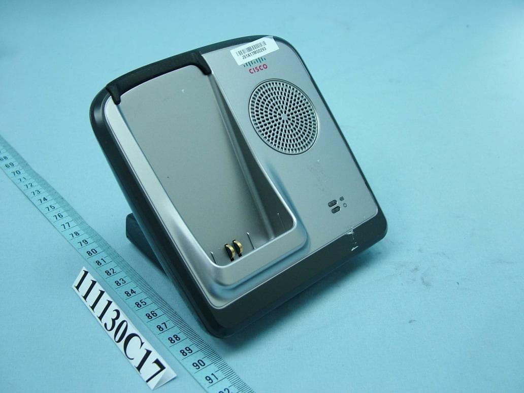
Click to zoom
Application Details
- Equipment Class
- DSS - Part 15 Spread Spectrum Transmitter
- Date of Grant
- Feb 23, 2012
- Application Purpose
- Original Equipment
- Date of Application
- Feb 23, 2012
- Equipment Note
- Cisco UC Phone 7925G Desktop Charger
- Frequency Range
- 2402.00000000 - 2480.00000000
- Company
- Cisco Systems Inc
- Country
- United States
Documents & Files
Document Text
Text extracted from the exhibit documents filed with the FCC. Open a document above to read the original.
Users Manual
Cisco CiscoCisco Cisco UC UCUC UC Phone 7925G Desktop Charger Phone 7925G Desktop ChargerPhone 7925G Desktop Charger Phone 7925G Desktop Charger This chapter describes the Cisco Unified Wireless IP Phone 7925G, 7925G Cisco Cisco Cisco Cisco UC UC UC UC Phone 7925G Desktop Charger overview Phone 7925G Desktop Charger overviewPhone 7925G Desktop Charger overview Phone 7925G Desktop Charger overview Phone 7925G Desktop Charger Phone 7925G Desktop ChargerPhone 7925G Desktop Charger Phone 7925G Desktop Charger This chapter describes the Cisco UC Phone 7925G Desktop Charger for use with Cisco Unified Wireless IP Phone 7925G, 7925G-EX, and 7926G. Phone 7925G Desktop Charger overview Phone 7925G Desktop Charger overviewPhone 7925G Desktop Charger overview Phone 7925G Desktop Charger overview Phone 7925G Desktop Charger for use with Cisco The Cisco UC Phone 7925G Desktop Charger provides the following features: • works on line power or from the spare battery for the phone • contains a Power LED and a Battery LED • contains a speakerphone, with the volume controlled by the phone volume buttons • supports Bluetooth headset through the speakerphone • charges the docked phone battery • contains an additional port at the back of the station for charging a spare batter Need a figure next: Cisco UC Phone 7925G Desktop Charger, shown with the Cisco Unified Wireless IP Phone 7925G - note: will identify the battery and power LEDs The Cisco UC Phone 7925G Desktop Charger supports the following phones: • •• •Cisco Unified Wireless IP Phone 7925G • •• •Cisco Unified Wireless IP Phone 7925G • •• •Cisco Unified Wireless IP Phone 7926G The two LEDs on the Cisco UC Phone 7925G Desktop Charger change color, as described in the following table. Phone 7925G Desktop Charger provides the following features: works on line power or from the spare battery for the phone contains a Power LED and a Battery LED contains a speakerphone, with the volume controlled by the phone volume buttons supports Bluetooth headset through the speakerphone charges the docked phone battery contains an additional port at the back of the station for charging a spare batter Phone 7925G Desktop Charger, shown with the Cisco Unified Wireless IP note: will identify the battery and power LEDs Phone 7925G Desktop Charger supports the following phones: Cisco Unified Wireless IP Phone 7925G Cisco Unified Wireless IP Phone 7925G-EX Cisco Unified Wireless IP Phone 7926G Phone 7925G Desktop Charger change color, as described in the following table. contains a speakerphone, with the volume controlled by the phone volume buttons contains an additional port at the back of the station for charging a spare battery Phone 7925G Desktop Charger, shown with the Cisco Unified Wireless IP Phone 7925G Desktop Charger change color, as described in the following table. The spare battery only charges when the Cisco U plugged into line power. The Cisco UC Phone 7925G Desktop Charger supports Bluetooth version 2.1 + EDR using Handsfree version 1.5. The speakerphone supports Acoustic Echo Cancellation (AER) and N (NR) to provide audio under a variety of noise environments. When the Cisco U Phone 7925G Desktop Charger establishes a Bluetooth connection, the AER and NR automatically disable. Connect charger to external power Connect charger to external powerConnect charger to external power Connect charger to external power Procedure ProcedureProcedure Procedure Step 1 Step 1Step 1 Step 1 Connect one end of the power cord to the station. Step 2 Step 2Step 2 Step 2 Plug the other end of the power cord into the nearest electrical output. The Power LED lights green. Pair charger and wireless phone After you have the Cisco U make the charger and your wireless phone communicate. This communication is called “pairing” because the phone and Cisco U communicate using Bluetooth technology. Charger Pin Design for BT On y charges when the Cisco UC Phone 7925G Desktop Charger is Phone 7925G Desktop Charger supports Bluetooth version 2.1 + EDR using Handsfree version 1.5. The speakerphone supports Acoustic Echo Cancellation (AER) and Noise Reduction (NR) to provide audio under a variety of noise environments. When the Cisco U Phone 7925G Desktop Charger establishes a Bluetooth connection, the AER and NR Connect charger to external power Connect charger to external powerConnect charger to external power Connect charger to external power one end of the power cord to the station. Plug the other end of the power cord into the nearest electrical output. Pair charger and wireless phone After you have the Cisco UC Phone 7925G Desktop Charger powered up, you must make the charger and your wireless phone communicate. This communication is called “pairing” because the phone and Cisco UC Phone 7925G Desktop Charger communicate using Bluetooth technology. or BT On Phone 7925G Desktop Charger is Phone 7925G Desktop Charger supports Bluetooth version 2.1 + EDR oise Reduction (NR) to provide audio under a variety of noise environments. When the Cisco UC Phone 7925G Desktop Charger establishes a Bluetooth connection, the AER and NR powered up, you must make the charger and your wireless phone communicate. This communication is Phone 7925G Desktop Charger Prerequisites • •• •The Cisco UC Phone 7925G Desktop Charger is connected to external power, or a charged spare battery installed. Procedure Step 1 Turn the phone on. Step 2 Choose tool > Phone Settings > Bluetooth > Device List Step 3 Press Scan. The phone scans for a Bluetooth device. The device name for the charger is “Cisco Dock 7900”. Step 4 Select Cisco Dock 7900 Step 5 Press the Answer/Send Dock phone in charger Prerequisites Phone 7925G Desktop Charger is connected to external power, or a charged spare battery installed. Turn the phone on. > Phone Settings > Bluetooth > Device List. . The phone scans for a Bluetooth device. The device name for the charger is “Cisco Dock 7900”. Cisco Dock 7900, and press Pair. Answer/Send button Dock phone in ch…
Text truncated - open the document above for the full version.
External Photos
Page 1 CONSTRUCTION PHOTOS OF EUT
ID Label/Location Info
170 West Tasman Drive Made In China San Jose, CA 95134-1706 USA size:54.55x34.4 Cisco UC Phone 7925G Model (): CP-DSKCH-7925G FCC ID: LDKCPDSKCH7925 CANADA IC: 2461B-CPDSKCH7925 Manufacturer (): Cisco Systems, Inc. XXXXXXXXX R 商標: 產品名稱: 產品型號: NCC證書號碼: Desktop Charger (UC ) KCC-CMM-TNY-XXXXX
ID Label/Location Info
FCC ID: LDKCPDSKCH7925 Bottom of device Label location
Internal Photos
Page 2 Page 3 Page 4 Page 5 Page 6 Page 7 Page 8 Page 9
RF Exposure Info
Report No.: SA111130C17 1 Report Format Version 4.0.0 RF EXPOSURE REPORT (FOR BLUETOOTH) REPORT NO.: SA111130C17 MODEL NO.: CP-DSKCH-7925G FCC ID: LDKCPDSKCH7925 RECEIVED: Nov. 30, 2011 TESTED: Dec. 09 ~ Dec. 16, 2011 ISSUED: Dec. 27, 2011 APPLICANT: Cisco Systems, Inc. ADDRESS: 170, West Tasman San Jose CA 95134 USA ISSUED BY: Bureau Veritas Consumer Products Services (H.K.) Ltd., Taoyuan Branch LAB ADDRESS: No. 47, 14th Ling, Chia Pau Vil., Lin Kou Dist., New Taipei City, Taiwan (R.O.C) TEST LOCATION: No. 19, Hwa Ya 2nd Rd, Wen Hwa Tsuen, Kwei Shan Hsiang, Taoyuan Hsien 333, Taiwan, R.O.C. This test report consists of 5 pages in total. It may be duplicated completely for legal use with the approval of the applicant. It should not be reproduced except in full, without the written approval of our laboratory. The client should not use it to claim product certification, approval or endorsement by any government agency. The test results in the report only apply to the tested sample. Report No.: SA111130C17 2 Report Format Version 4.0.0 TABLE OF CONTENTS RELEASE CONTROL RECORD ........................................................................................... 3 1. CERTIFICATION ........................................................................................................ 4 2. REDUCED CONDITION FOR SAR............................................................................ 5 3. MAXIMUM MEASURED POWER OF EUT ................................................................ 5 4. CONCLUSION ........................................................................................................... 5 Report No.: SA111130C17 3 Report Format Version 4.0.0 RELEASE CONTROL RECORD ISSUE NO. REASON FOR CHANGE DATE ISSUED Original release NA Dec. 27, 2011 Report No.: SA111130C17 4 Report Format Version 4.0.0 1. CERTIFICATION PRODUCT: Cisco UC Phone 7925G Desktop Charger MODEL: CP-DSKCH-7925G BRAND: Cisco APPLICANT: Cisco Systems, Inc. TESTED: Dec. 09 ~ Dec. 16, 2011 TEST SAMPLE: ENGINEERING SAMPLE STANDARDS: FCC Part 2 (Section 2.1093) FCC OET Bulletin 65, Supplement C (01-01) IEEE C95.1 The above equipment (model: CP-DSKCH-7925G) have been tested by Bureau Veritas Consumer Products Services (H.K.) Ltd., Taoyuan Branch, and found compliance with the requirement of the above standards. The test record, data evaluation & Equipment Under Test (EUT) configurations represented herein are true and accurate accounts of the measurements of the sample’s EMC characteristics under the conditions specified in this report. PREPARED BY : , DATE: Dec. 27, 2011 Ivonne Wu / Senior Specialist APPROVED BY : , DATE: Dec. 27, 2011 Gary Chang / Technical Manager Report No.: SA111130C17 5 Report Format Version 4.0.0 2. REDUCED CONDITION FOR SAR When output power is ≤ 60/f(GHz) mW, SAR evaluation is not required. 3. MAXIMUM MEASURED POWER OF EUT Mode Conducted power (dBm) Antenna Gain (dBi) EIRP (dBm) Threshold for SAR (dBm) Bluetooth 0.26 0 0.26 13.84 4. CONCLUSION No SAR evaluation is required since output power of EUT is less than threshold of SAR.
Test Report
Report No.: RF111130C17 1 Report Format Version 4.0.0 FCC TEST REPORT (Bluetooth) REPORT NO.: RF111130C17 MODEL NO.: CP-DSKCH-7925G FCC ID: LDKCPDSKCH7925 RECEIVED: Nov. 30, 2011 TESTED: Dec. 09 ~ Dec. 16, 2011 ISSUED: Dec. 27, 2011 APPLICANT: Cisco Systems, Inc. ADDRESS: 170, West Tasman San Jose CA 95134 USA ISSUED BY: Bureau Veritas Consumer Products Services (H.K.) Ltd., Taoyuan Branch LAB ADDRESS: No. 47, 14th Ling, Chia Pau Vil., Lin Kou Dist., New Taipei City, Taiwan (R.O.C) TEST LOCATION: No. 19, Hwa Ya 2nd Rd, Wen Hwa Tsuen, Kwei Shan Hsiang, Taoyuan Hsien 333, Taiwan, R.O.C. This test report consists of 60 pages in total. It may be duplicated completely for legal use with the approval of the applicant. It should not be reproduced except in full, without the written approval of our laboratory. The client should not use it to claim product certification, approval or endorsement by TAF or any government agency. The test results in the report only apply to the tested sample. Report No.: RF111130C17 2 Report Format Version 4.0.0 TABLE OF CONTENTS RELEASE CONTROL RECORD .............................................................................................4 1. CERTIFICATION ..........................................................................................................5 2. SUMMARY OF TEST RESULTS ..................................................................................6 2.1 MEASUREMENT UNCERTAINTY ...............................................................................6 3. GENERAL INFORMATION ..........................................................................................7 3.1 GENERAL DESCRIPTION OF EUT .............................................................................7 3.2 DESCRIPTION OF TEST MODES ...............................................................................8 3.2.1 CONFIGURATION OF SYSTEM UNDER TEST ..........................................................9 3.2.2 DESCRIPTION OF SUPPORT UNITS .........................................................................9 3.2.3 TEST MODE APPLICABILITY AND TESTED CHANNEL DETAIL .............................. 10 3.3 GENERAL DESCRIPTION OF APPLIED STANDARDS ............................................. 12 4. TEST TYPES AND RESULTS .................................................................................... 13 4.1 RADIATED EMISSION MEASUREMENT .................................................................. 13 4.1.1 LIMITS OF RADIATED EMISSION MEASUREMENT ................................................ 13 4.1.2 TEST INSTRUMENTS ............................................................................................... 14 4.1.3 TEST PROCEDURES ................................................................................................ 15 4.1.4 DEVIATION FROM TEST STANDARD ...................................................................... 15 4.1.5 TEST SETUP ............................................................................................................. 16 4.1.6 EUT OPERATING CONDITIONS ............................................................................... 16 4.1.7 TEST RESULTS ........................................................................................................ 17 4.2 CONDUCTED EMISSION MEASUREMENT ............................................................. 26 4.2.1 LIMITS OF CONDUCTED EMISSION MEASUREMENT ........................................... 26 4.2.2 TEST INSTRUMENTS ............................................................................................... 26 4.2.3 TEST PROCEDURES ................................................................................................ 27 4.2.4 DEVIATION FROM TEST STANDARD ...................................................................... 27 4.2.5 TEST SETUP ............................................................................................................. 28 4.2.6 EUT OPERATING CONDITIONS ............................................................................... 28 4.2.7 TEST RESULTS ........................................................................................................ 29 4.3 NUMBER OF HOPPING FREQUENCY USED .......................................................... 31 4.3.1 LIMIT OF HOPPING FREQUENCY USED ................................................................ 31 4.3.2 TEST SETUP ............................................................................................................. 31 4.3.3 TEST INSTRUMENTS ............................................................................................... 31 4.3.4 TEST PROCEDURES ................................................................................................ 31 4.3.5 DEVIATION FROM TEST STANDARD ...................................................................... 31 4.3.6 TEST RESULTS ........................................................................................................ 31 4.4 DWELL TIME ON EACH CHANNEL .......................................................................... 34 4.4.1 LIMIT OF DWELL TIME USED .................................................................................. 34 4.4.2 TEST SETUP ............................................................................................................. 34 4.4.3 TEST INSTRUMENTS ............................................................................................... 34 4.4.4 TEST PROCEDURES ................................................................................................ 34 4.4.5 DEVIATION FROM TEST STANDARD ...................................................................... 34 Report No.: RF111130C17 3 Report Format Version 4.0.0 4.4.6 TEST RESULTS ........................................................................................................ 35 4.5 CHANNEL BANDWIDTH .....................................................…
Text truncated - open the document above for the full version.
Test Setup Photos
1 PHOTOGRAPHS OF THE TEST CONFIGURATION CONDUCTED EMISSION TEST 2 RADIATED EMISSION TEST
Contact Information
Applicant
Samuel Kim(Manager, Engineering)
Technical Contact
Bureau Veritas CPS (H.K.) Ltd. Taoyuan BranchGary Chang
[email protected]886-3-3183232
No. 19, Hwa Ya 2nd Rd., Kwei Shan Hsiang · Taoyuan Hsien · Taiwan
Non-Technical Contact
Bureau Veritas CPS (H.K.) Ltd. Taoyuan BranchNatacha Chen
[email protected]886-3-3183232
Test Firm
Bureau Veritas CPS (H.K.) Ltd. Taoyuan BranchRichard Chen
Technical Specifications
| # | Rule Parts | Frequency Range | Power Output |
|---|---|---|---|
| 1 | 15C | 2.40 GHz - 2.48 GHz | 1.00 mW |
Other Applications from Cisco Systems Inc

LDKJ98213058
May 25, 2026Wireless Phone
Equipment Class
DSS - Part 15 Spread Spectrum TransmitterLDKIW9165E
Aug 20, 2024Wi-Fi 6E Outdoor Access Point
Equipment Class
6SD - 15E 6 GHz Standard Power Access PointLDKIW9165DH
Aug 05, 2024Wi-Fi 6E Outdoor Access Point
Equipment Class
6SD - 15E 6 GHz Standard Power Access PointLDKUSBC2857
Jul 22, 2024Cisco Headset USB-C Adapter
Equipment Class
DSS - Part 15 Spread Spectrum TransmitterLDKESPRD2922
May 09, 2024UC Phone
Equipment Class
NII - Unlicensed National Information Infrastructure TX