LDKDPH150856Femtocell
Cisco Systems Inc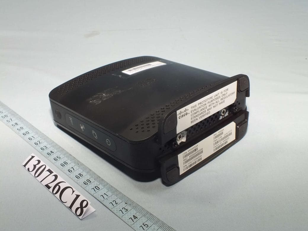
Click to zoom
Application Details
- Equipment Class
- PCB - PCS Licensed Transmitter
- Date of Grant
- Oct 19, 2013
- Application Purpose
- Original Equipment
- Date of Application
- Oct 19, 2013
- Equipment Note
- Femtocell
- Frequency Range
- 1932.40000000 - 1987.60000000
- Company
- Cisco Systems Inc
- Country
- United States
Documents & Files
Document Text
Text extracted from the exhibit documents filed with the FCC. Open a document above to read the original.
Users Manual
AT&T 3G MicroCell ™ User Guide Getting Started Requirements 4 Getting to Know your Device 4 Frequently Asked Questions 5 Overview 7 Step 1: Activate your device online 8 Step 2: Connect your device to the Internet 9 Step 3: Power on your device 10 Step 4: Wait while your device connects 10 Step 5: Confirm your success 10 Troubleshooting Help with Activating your MicroCell 12 Help after Activating your MicroCell 15 Additional Information Understanding the Lights on your MicroCell 18 Important Safety Instructions 20 Firewall Settings 23 Specifications 23 RF Exposure 24 FCC Compliance 24 Index 26 One-Year Limited Warranty Back Cover Table of Contents 5 AT&T 3G MicroCell User Guide | Getting Started 4 Getting to Know your Device Requirements To use the AT&T 3G MicroCell™, you will need: • High-speed Internet service such as U-verse®, DSL, or cable. For best performance, download speeds of at least 1.5 Mbps and upload speeds of at least 256 Kbps are recommended. There are no restrictions on broadband service providers. Satellite or wireless internet service is not supported. • Modem or router with at least one open ethernet port. • Computer with Internet access to activate your device. Package Contents • AT&T 3G MicroCell™ • Yellow ethernet cable • AC power adapter • Quick Start • User Guide STATUS INDICATORS Your MicroCell uses indicator lights on the front of the device to show service status. HARDwARe pORTS Color coded connection ports are located on the back of the device. Frequently Asked Questions I completed my MicroCell online activation at the AT&T store. Do I have to do it again? No, you can skip Step 3 and proceed to Step 4 of the setup process. what’s the best location for the MicroCell? Your MicroCell works best within three feet of a window and not in a basement or closet. You will improve the chances of receiving a GPS signal when you install your MicroCell: • On first floor or above basement level. • Next to a window with a clear, unobstructed view of the sky. • At least one foot away from other wireless broadcasting devices. • When the weather is clear (no clouds or rain). will all cell phones work with my MicroCell? All 3G, 4G and 4G LTE cell phones that receive wireless service from AT&T will work with the MicroCell if they are added online to the MicroCell’s approved user list. IMpORTANT NOTe: When adding a wireless number to your approved user list, that handset will need to be restarted (turned off and back on again) when in range of your MicroCell. This is a one-time occurrence and only needs to be done the first time you add the wireless number to your approved user list. Do I need to change any settings on my AT&T cell phone to make it work with my MicroCell? No, you don’t have to change anything on your phone. If your AT&T cell phone number is on your approved user list, it should work. what is an approved user list? The approved user list contains the phone numbers of friends, family and associates that you allow to use your MicroCell while they are at your home or office. You can only add people to this list who have an AT&T wireless service plan. When they make phone calls, they will use their own minutes and service plan. To add an AT&T 3G, 4G or 4G LTE wireless cell phone number to your approved user list, go to att.com/3GMicroCell and manage your settings. what type of Internet service does the MicroCell need? The MicroCell uses high-speed Internet service such as AT&T U-verse, DSL, or cable. For best performance, your service should have download speeds of at least 1.5 Mbps and upload speeds of at least 256 Kbps. You can use any high-speed Internet service provider. Satellite or wireless internet service is not supported. Contact your Internet Service Provider if your Internet service is slower than minimum requirements. Ethernet Power Power Ethernet GPS 3G AT&T 3G MicroCell User Guide | Getting Started 67 why did my MicroCell lights go off during activation? Your MicroCell automatically checks for software updates each time you turn it on. If necessary, the MicroCell downloads updated software and then restarts. will my MicroCell slow down my network? The MicroCell takes up very little of your bandwidth. Downloading music, videos, or other large files may impact the bandwidth available for your MicroCell and affect voice quality. Should I use my MicroCell for data instead of wi-Fi? The MicroCell supports data usage. However, it is not intended to be a replacement for your wireless network (Wi-Fi). Data over Wi-Fi doesn’t affect your wireless plan and provides best performance for Wi-Fi capable cell phones and other devices. The MicroCell is a great supplement for data on cell phones that aren’t Wi-Fi capable. How do I move my MicroCell to a new location? Use the Quick Start for setup instructions and then update your account online with the new address by visiting att.com/3GMicroCell and manage your settings. NOTe: The new location must be in an area where AT&T is licensed to provide service. How do I purchase the Unlimited MicroCell Calling feature? Go to www.att.com/mywireless. Log in to your online wireless account, click the “I want to...” dropdown, hover the mouse over “Manage my plan & services”, and click “Add or change a service”. Scroll down and select “AT&T Unlimited MicroCell Calling.” Is there a 3G MicroCell Mobile App? Yes, you can download the free 3G MicroCell iPhone App at the Apple App Store. The app allows you to activate and manage your MicroCell settings, including adding a new approved user, changing your location, and updating your email address. I have more questions. For more information about your MicroCell, visit att.com/3GMicroCell. Frequently Asked Questions (continued) Overview This guide will take you step-by-step through configuration, activation, and confirmation. STep 3 Power on your device STep 5 Confirm your success STep 2 Connect your device to the Internet STep 4 Wait while your device connects 90 MIN STep 1 Activate your …
Text truncated - open the document above for the full version.
Cover Letter(s)
EDCS-1216337 09/10/2013 Subject : Authorized signatures The following people are authorized by Cisco Systems to sign documents for FCC product approval under FCC Grantee code LDK on behalf of the company. Further this right is extended to any regular Cisco employee as deemed necessary. David A, Case Jim Nicholson Trinh Tien Donn Foster Howard Ji Phil Carranco Jose Aguirre Collin Wilson Lisa Bevington Andy Griffin Mark King Dave Wilson Allan Beecroft Bob Lyall Pushpinder Sawanni Julius “Bud” Chiller Chuck Troia Francois Caron Steve Granzella Rob Hastings Dilip Patel Rick Ransdell Regards Kenny Wee Cisco Systems
Cover Letter(s)
SCS-F18: Project and Product Certification Representative Authorization Letter Page 1 of 2 Rev 3.0 775 Montague Expressway Milpitas, CA 95035 Tel: 408-526-1188 Fax: 408-526-1088 Email: [email protected] Project and Product Certification Representative Authorization Letter Reason for Amendment (current / obsolete) Revision History Approved Date From To Initial Release (obsolete) 1.0 1.0 Nov-14-2006 Revised wording (obsolete) 1.0 2.0 Sept–25-2007 Updated company template (current) 2.0 3.0 Jan-31-2012 SCS-F18: Project and Product Certification Representative Authorization Letter Page 2 of 2 Rev 3.0 Bureau Veritas Consumer Products Services Electrical & Electronic Business Line, Taiwan Branch October 14, 2013 To: SIEMIC, INC. 775 Montague Expressway, Milpitas, CA 95035 USA Dear Sir/Madam, Re: Project and Product Certification Representative Authorization Letter We, Bureau Veritas Consumer Products Services Electrical & Electronic Business Line, Taiwan Branch hereby authorize SIEMIC, INC. to act as a Certification Body for certifying for the following project(s): Femtocell, DPH-154 We affirm that between SIEMIC and Bureau Veritas Consumer Products Services Electrical & Electronic Business Line, Taiwan Branch, any difference in understanding, including test plan, measurement methods, applicable standards and relevant procedures and processes have been resolved prior to commencement of testing activities. Sincerely, Daniel Lee / Vice-President Tel: +886-3-318-3232 Ext. 1857 Mobile: +886-970510189 E-mail: [email protected]
External Photos
1 CONSTRUCTION PHOTOS OF EUT
ID Label/Location Info
Label Location
Internal Photos
2 3 4 5 6 7 8 9
RF Exposure Info
Report No.: SA130726C18 1 of 5 Report Format Version 5.1.0 RF EXPOSURE REPORT REPORT NO.: SA130726C18 MODEL NO.: DPH-154 FCC ID: LDKDPH150856 RECEIVED: Jul. 14, 2013 ISSUED: Sep. 24, 2013 APPLICANT: Cisco Systems, Inc ADDRESS: 170 Tasman Drive, San Jose, CA95134, USA ISSUED BY: Bureau Veritas Consumer Products Services (H.K.) Ltd., Taoyuan Branch LAB ADDRESS: No. 47, 14th Ling, Chia Pau Vil., Lin Kou Dist., New Taipei City, Taiwan, R.O.C. TEST LOCATION: No. 19, Hwa Ya 2nd Rd, Wen Hwa Tsuen, Kwei Shan Hsiang, Taoyuan Hsien 333, Taiwan, R.O.C. This report is for your exclusive use. Any copying or replication of this report to or for any other person or entity, or use of our name or trademark, is permitted only with our prior written permission. This report sets forth our findings solely with respect to the test samples identified herein. The results set forth in this report are not indicative or representative of the quality or characteristics of the lot from which a test sample was taken or any similar or identical product unless specifically and expressly noted. Our report includes all of the tests requested by you and the results thereof based upon the information that you provided to us. You have 60 days from date of issuance of this report to notify us of any material error or omission caused by our negligence, provided, however, that such notice shall be in writing and shall specifically address the issue you wish to raise. A failure to raise such issue within the prescribed time shall constitute your unqualified acceptance of the completeness of this report, the tests conducted and the correctness of the report contents. Unless specific mention, the uncertainty of measurement has been explicitly taken into account to declare the compliance or non-compliance to the specification. This report should not be used by the client to claim product certification, approval, or endorsement by TAF or any government agencies. Report No.: SA130726C18 2 of 5 Report Format Version 5.1.0 TABLE OF CONTENTS RELEASE CONTROL RECORD .............................................................................................. 3 1. CERTIFICATION ............................................................................................................... 4 2. RF Exposure ..................................................................................................................... 5 2.1 LIMITS FOR MAXIMUM PERMISSIBLE EXPOSURE (MPE) ........................................... 5 2.2 MPE calculation Formula .................................................................................................. 5 2.3 Classification ..................................................................................................................... 5 2.4 calculation result of maximum conducted power ............................................................... 5 Report No.: SA130726C18 3 of 5 Report Format Version 5.1.0 RELEASE CONTROL RECORD ISSUE NO. REASON FOR CHANGE DATE ISSUED SA130726C18 Original release Sep. 24, 2013 Report No.: SA130726C18 4 of 5 Report Format Version 5.1.0 1. CERTIFICATION PRODUCT: Femtocell MODEL NO.: DPH-154 BRAND: Cisco APPLICANT: Cisco Systems, Inc TEST SAMPLE: Production Unit P/N: SC-DPH154-4U-ATT STANDARDS: FCC Part 2 (Section 2.1091) FCC OET Bulletin 65, Supplement C (01-01) IEEE C95.1 The above equipment (model: DPH-154) has been tested by Bureau Veritas Consumer Products Services (H.K.) Ltd., Taoyuan Branch, and found compliance with the requirement of the above standards. The test record, data evaluation & Equipment Under Test (EUT) configurations represented herein are true and accurate accounts of the measurements of the sample’s EMC characteristics under the conditions specified in this report. PREPARED BY : , DATE : Sep. 24, 2013 Vera Huang / Specialist APPROVED BY : , DATE : Sep. 24, 2013 Gordon Lin / Assistant Manager Report No.: SA130726C18 5 of 5 Report Format Version 5.1.0 2. RF EXPOSURE 2.1 LIMITS FOR MAXIMUM PERMISSIBLE EXPOSURE (MPE) FREQUENCY RANGE (MHz) ELECTRIC FIELD STRENGTH (V/m) MAGNETIC FIELD STRENGTH (A/m) POWER DENSITY (mW/cm 2 ) AVERAGE TIME (minutes) LIMITS FOR GENERAL POPULATION / UNCONTROLLED EXPOSURE 300-1500 ... ... F/1500 30 1500-100,000 ... ... 1.0 30 F = Frequency in MHz 2.2 MPE CALCULATION FORMULA Pd = (Pout*G) / (4*pi*r 2 ) where Pd = power density in mW/cm 2 Pout = output power to antenna in mW G = gain of antenna in linear scale Pi = 3.1416 R = distance between observation point and center of the radiator in cm 2.3 CLASSIFICATION The antenna of this product, under normal use condition, is at least 20cm away from the body of the user. So, this device is classified as Mobile Device. This product is a single radio device, so no simultaneous transmission of this product. 2.4 CALCULATION RESULT OF MAXIMUM CONDUCTED POWER Frequency Band (MHz) Conducted Avg. Power (dBm) Antenna Gain (dBi) E.I.R.P. (mW) Power Density (mW/cm 2 ) Limit (mW/cm 2 ) WCDMA Band II 21 2.96 248.89 0.050 1.00 WCDMA Band V 21 2.5 223.87 0.045 0.55
Test Report
Report No.: RF130726C18 1 of 28 Report Format Version 5.0.0 FCC TEST REPORT (PART 22) REPORT NO.: RF130726C18 MODEL NO.: DPH-154 FCC ID: LDKDPH150856 RECEIVED: Jul. 14, 2013 TESTED: Jul. 31, 2013 ~ Sep. 17, 2013 ISSUED: Sep. 24, 2013 APPLICANT: Cisco Systems, Inc ADDRESS: 170 Tasman Drive, San Jose, CA95134, USA ISSUED BY: Bureau Veritas Consumer Products Services (H.K.) Ltd., Taoyuan Branch LAB ADDRESS: No. 47, 14th Ling, Chia Pau Vil., Lin Kou Dist., New Taipei City, Taiwan ( R.O.C. ) TEST LOCATION: No. 19, Hwa Ya 2nd Rd, Wen Hwa Tsuen, Kwei Shan Hsiang, Taoyuan Hsien 333, Taiwan, R.O.C. This report is for your exclusive use. Any copying or replication of this report to or for any other person or entity, or use of our name or trademark, is permitted only with our prior written permission. This report sets forth our findings solely with respect to the test samples identified herein. The results set forth in this report are not indicative or representative of the quality or characteristics of the lot from which a test sample was taken or any similar or identical product unless specifically and expressly noted. Our report includes all of the tests requested by you and the results thereof based upon the information that you provided to us. You have 60 days from date of issuance of this report to notify us of any material error or omission caused by our negligence, provided, however, that such notice shall be in writing and shall specifically address the issue you wish to raise. A failure to raise such issue within the prescribed time shall constitute your unqualified acceptance of the completeness of this report, the tests conducted and the correctness of the report contents. Unless specific mention, the uncertainty of measurement has been explicitly taken into account to declare the compliance or non-compliance to the specification This report should not be used by the client to claim product certification, approval, or endorsement by TAF or any government agencies. Report No.: RF130726C18 2 of 28 Report Format Version 5.0.0 TABLE OF CONTENTS RELEASE CONTROL RECORD ................................................................................................ 3 1 CERTIFICATION .......................................................................................................... 4 2 SUMMARY OF TEST RESULTS .................................................................................. 5 2.1 MEASUREMENT UNCERTAINTY ............................................................................... 5 2.2 TEST SITE AND INSTRUMENTS ................................................................................ 6 3 GENERAL INFORMATION ........................................................................................... 7 3.1 GENERAL DESCRIPTION OF EUT ............................................................................. 7 3.2 CONFIGURATION OF SYSTEM UNDER TEST .......................................................... 8 3.3 DESCRIPTION OF SUPPORT UNITS ......................................................................... 8 3.4 TEST ITEM AND TEST CONFIGURATION ................................................................. 9 3.5 EUT OPERATING CONDITIONS ............................................................................... 10 3.6 GENERAL DESCRIPTION OF APPLIED STANDARDS ............................................ 10 4 TEST TYPES AND RESULTS .....................................................................................11 4.1 OUTPUT POWER MEASUREMENT ..........................................................................11 4.1.1 LIMITS OF OUTPUT POWER MEASUREMENT ........................................................11 4.1.2 TEST PROCEDURES .................................................................................................11 4.1.3 TEST SETUP ............................................................................................................. 12 4.1.4 TEST RESULTS ......................................................................................................... 13 4.2 FREQUENCY STABILITY MEASUREMENT ............................................................. 14 4.2.1 LIMITS OF FREQUENCY STABILITY MEASUREMENT ........................................... 14 4.2.2 TEST PROCEDURE .................................................................................................. 14 4.2.3 TEST SETUP ............................................................................................................. 14 4.2.4 TEST RESULTS ......................................................................................................... 15 4.3 OCCUPIED BANDWIDTH MEASUREMENT ............................................................. 16 4.3.1 TEST PROCEDURES ................................................................................................ 16 4.3.2 TEST SETUP ............................................................................................................. 16 4.3.3 TEST RESULTS ......................................................................................................... 17 4.4 BAND EDGE MEASUREMENT ................................................................................. 18 4.4.1 LIMITS OF BAND EDGE MEASUREMENT ............................................................... 18 4.4.2 TEST SETUP ............................................................................................................. 18 4.4.3 TEST PROCEDURES ................................................................................................ 18 4.4.4 TEST RESULTS ......................................................................................................... 19 4.5 CONDUCTED SPURIOUS EMISSIONS .................................................................... 20 4.5.1 LIMITS OF CONDUCTED SPURIOUS EMISSIONS MEASUREMENT .................... 20 4.5.2 TEST PROCEDURE ....................................…
Text truncated - open the document above for the full version.
Test Report
Report No.: RF130726C18-1 1 of 31 Report Format Version 5.0.0 FCC TEST REPORT (PART 24) REPORT NO.: RF130726C18-1 MODEL NO.: DPH-154 FCC ID: LDKDPH150856 RECEIVED: Jul. 14, 2013 TESTED: Jul. 14, 2013 ~ Sep. 17, 2013 ISSUED: Sep. 24, 2013 APPLICANT: Cisco Systems, Inc ADDRESS: 170 Tasman Drive, San Jose, CA95134, USA ISSUED BY: Bureau Veritas Consumer Products Services (H.K.) Ltd., Taoyuan Branch LAB ADDRESS: No. 47, 14th Ling, Chia Pau Vil., Lin Kou Dist., New Taipei City, Taiwan ( R.O.C. ) TEST LOCATION: No. 19, Hwa Ya 2nd Rd, Wen Hwa Tsuen, Kwei Shan Hsiang, Taoyuan Hsien 333, Taiwan, R.O.C. This report is for your exclusive use. Any copying or replication of this report to or for any other person or entity, or use of our name or trademark, is permitted only with our prior written permission. This report sets forth our findings solely with respect to the test samples identified herein. The results set forth in this report are not indicative or representative of the quality or characteristics of the lot from which a test sample was taken or any similar or identical product unless specifically and expressly noted. Our report includes all of the tests requested by you and the results thereof based upon the information that you provided to us. You have 60 days from date of issuance of this report to notify us of any material error or omission caused by our negligence, provided, however, that such notice shall be in writing and shall specifically address the issue you wish to raise. A failure to raise such issue within the prescribed time shall constitute your unqualified acceptance of the completeness of this report, the tests conducted and the correctness of the report contents. Unless specific mention, the uncertainty of measurement has been explicitly taken into account to declare the compliance or non-compliance to the specification This report should not be used by the client to claim product certification, approval, or endorsement by TAF or any government agencies. Report No.: RF130726C18-1 2 of 31 Report Format Version 5.0.0 TABLE OF CONTENTS RELEASE CONTROL RECORD ................................................................................................ 4 1 CERTIFICATION .......................................................................................................... 5 2 SUMMARY OF TEST RESULTS .................................................................................. 6 2.1 MEASUREMENT UNCERTAINTY ............................................................................... 6 2.2 TEST SITE AND INSTRUMENTS ................................................................................ 7 3 GENERAL INFORMATION ........................................................................................... 8 3.1 GENERAL DESCRIPTION OF EUT ............................................................................. 8 3.2 CONFIGURATION OF SYSTEM UNDER TEST .......................................................... 9 3.3 DESCRIPTION OF SUPPORT UNITS ......................................................................... 9 3.4 TEST ITEM AND TEST CONFIGURATION ............................................................... 10 3.5 EUT OPERATING CONDITIONS ................................................................................11 3.6 GENERAL DESCRIPTION OF APPLIED STANDARDS .............................................11 4 TEST TYPES AND RESULTS .................................................................................... 12 4.1 OUTPUT POWER MEASUREMENT ......................................................................... 12 4.1.1 LIMITS OF OUTPUT POWER MEASUREMENT ....................................................... 12 4.1.2 TEST PROCEDURES ................................................................................................ 12 4.1.3 TEST SETUP ............................................................................................................. 13 4.1.4 TEST RESULTS ......................................................................................................... 14 4.2 FREQUENCY STABILITY MEASUREMENT ............................................................. 15 4.2.1 LIMITS OF FREQUENCY STABILITY MEASUREMENT ........................................... 15 4.2.2 TEST PROCEDURE .................................................................................................. 15 4.2.3 TEST SETUP ............................................................................................................. 15 4.2.4 TEST RESULTS ......................................................................................................... 16 4.3 OCCUPIED BANDWIDTH MEASUREMENT ............................................................. 17 4.3.1 TEST PROCEDURES ................................................................................................ 17 4.3.2 TEST SETUP ............................................................................................................. 17 4.3.3 TEST RESULTS ......................................................................................................... 18 4.4 PEAK TO AVERAGE RATIO ...................................................................................... 19 4.4.1 LIMITS OF PEAK TO AVERAGE RATIO MEASUREMENT ....................................... 19 4.4.2 TEST SETUP ............................................................................................................. 19 4.4.3 TEST PROCEDURES ................................................................................................ 19 4.4.4 TEST RESULTS ......................................................................................................... 20 4.5 BAND EDGE MEASUREMENT ................................................................................. 21 4.5.1 LIMITS OF BAND EDGE MEASUREMENT ............................................................... 21 4.5.2 TEST SETUP ............…
Text truncated - open the document above for the full version.
Test Setup Photos
1 PHOTOGRAPHS OF THE TEST CONFIGURATION (Part 22/24)
Contact Information
Applicant
Samuel Kim(Manager, Engineering)
Test Firm
Bureau Veritas CPS (H.K.) Ltd., Taoyuan BranchRichard Chen
Technical Specifications
| # | Rule Parts | Frequency Range | Power Output | Emission | Tolerance |
|---|---|---|---|---|---|
| 2 | 24E | 1.93 GHz - 1.99 GHz | 310.00 mW | 4M18F9W | 0.007 ppm |
Other Applications from Cisco Systems Inc

LDKJ98213058
May 25, 2026Wireless Phone
Equipment Class
DSS - Part 15 Spread Spectrum TransmitterLDKIW9165E
Aug 20, 2024Wi-Fi 6E Outdoor Access Point
Equipment Class
6SD - 15E 6 GHz Standard Power Access PointLDKIW9165DH
Aug 05, 2024Wi-Fi 6E Outdoor Access Point
Equipment Class
6SD - 15E 6 GHz Standard Power Access PointLDKUSBC2857
Jul 22, 2024Cisco Headset USB-C Adapter
Equipment Class
DSS - Part 15 Spread Spectrum TransmitterLDKESPRD2922
May 09, 2024UC Phone
Equipment Class
NII - Unlicensed National Information Infrastructure TX