LDKDX700976Desktop Telepresence Device
Cisco Systems Inc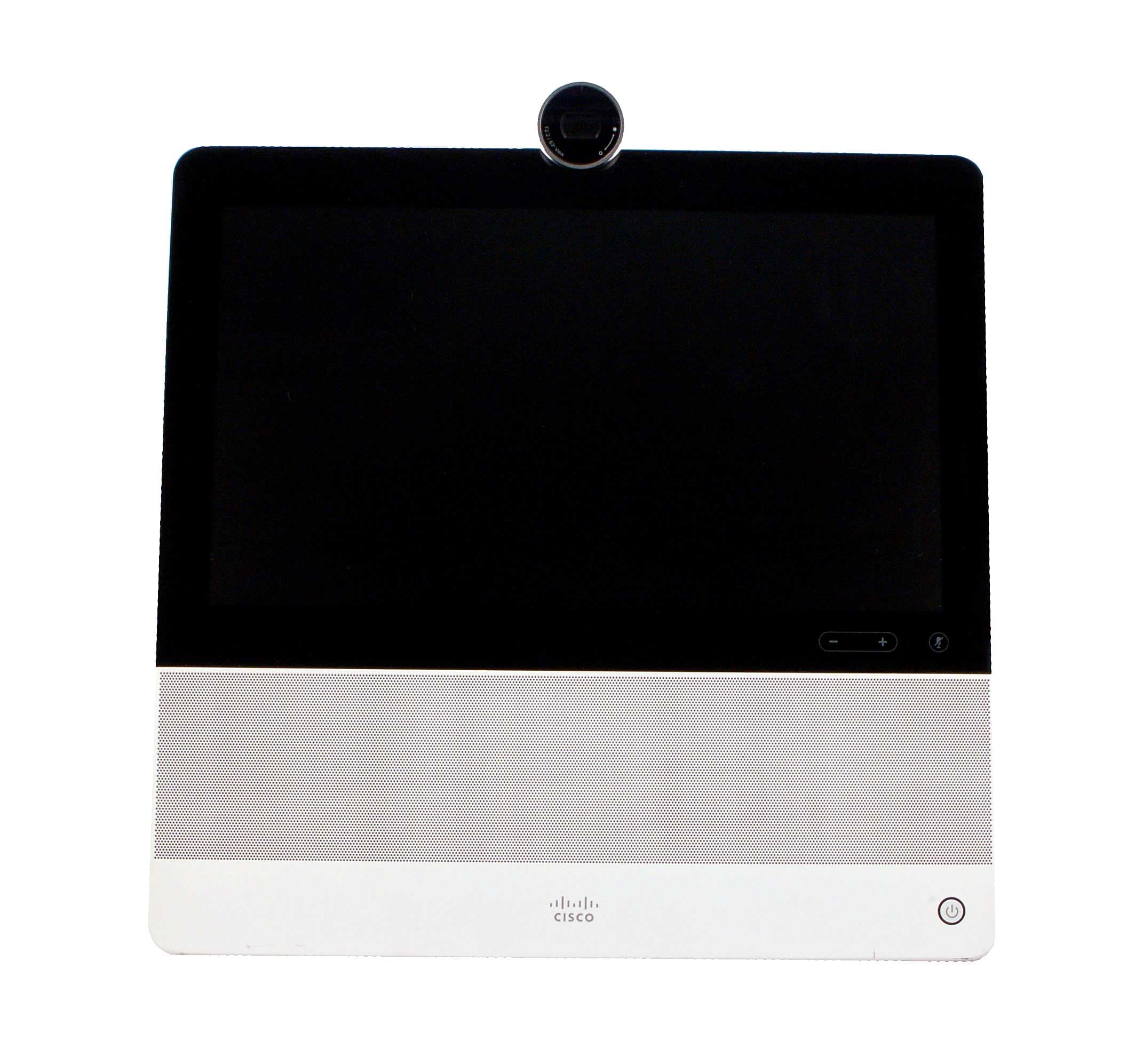
Click to zoom
Application Details
- Equipment Class
- DTS - Digital Transmission System
- Date of Grant
- Jul 31, 2014
- Application Purpose
- Original Equipment
- Date of Application
- Jul 30, 2014
- Equipment Note
- Desktop Telepresence Device
- Frequency Range
- 5745.00000000 - 5825.00000000
- Company
- Cisco Systems Inc
- Country
- United States
Documents & Files
Document Text
Text extracted from the exhibit documents filed with the FCC. Open a document above to read the original.
Users Manual
Front View and Home Screen Rear View Cisco DX70 Quick Reference Guide Draft 2014.02.14 REVIEW DRAFT—CISCO CONFIDENTIAL 1. USB ports 2.HDMI sockets (future use) 3.Connect y our PC LAN here to let your DX70 and PC share a common LAN connection 4.LAN connection 5.Power supply socket. Phone Only Mode Standard Mode Show Self View Tap the Settings icon ( ) in the upper right corner and select Self view from the menu. Forward All Calls 1.Tap the Settings icon ( ) in the upper right corner and select Forward all calls. 2. You will be prompted to specify a target phone number. 3.To cancel Forward all calls, repeat the process. Turn On Do Not Disturb Tap the Settings icon ( ) in the upper right corner and select Do not disturb. Available only when feature has been activated by your Administrator. Mute a Call Press the Microphone mute button on the right side of the system. To unmute a call, press again. Stop Your Video Transmission Turn the camera shutter counter-clockwise. To resume video transmission, turn shutter clockwise. Voicemail The Message Waiting Icon (MWI) light indicates that you have a new voice message. To view your voice messages: 1. Tap Recents. 2.Tap Call voicemail. Play voice message: Tap Play. If your system operates in Standard Mode, you must start the Phone App to use the system as a phone. To start the Phone App tap the Phone icon ( ) in the left corner of the black bottom bar. The Phone icon is shown in Standard Mode only. The usual Android navigation buttons (Back, Home and Recently Used Apps)will be shown when the Phone App is running. Note! The descriptions provided in this document assume that the system either is in Phone Only Mode or that the Phone Application is running. Place calls Access your list of Contacts Display the list of Recent calls Display any Voice Mail (Messages) View PC (if applicable) Display the Settings menu (icon in upper right corner). If your system operates in Phone Only Mode (modes are set up by your Administrator), the following functions are available: Camera with privacy shutter, turn counter-clockwise to shut and clockwise to open Microphone mute button and loudspeaker volume controls SD card slot and connectors for headset and USB. Loudspeaker Power On/Off. EFT DRAFT - CISCO CONFIDENTIAL DO NOT DISTRIBUTE Americas Headquarters Cisco Systems, Inc. 170 West Tasman Drive San Jose, CA 95134-1706, USA http://www.cisco.com Cisco and the Cisco logo are trademarks or registered trademarks of Cisco and/or its affiliates in the U.S. and other countries. To view a list of Cisco trademarks, go to this URL:www.cisco.com/ go/trademarks. Third-party trademarks mentioned are the property of their respective owners. The use of the word partner does not imply a partnership relationship between Cisco and any other company. (1110R) © 2014 Cisco Systems, Inc. All rights reserved. Google, Google Play, Android and other marks are trademarks of Google Inc. The terms HDMI and HDMI High-Definition Multimedia Interface, and the HDMI Logo are trademarks or registered trademarks of HDMI Licensing LLC in the United States and other countries. REVIEW DRAFT—CISCO CONFIDENTIAL Place a CallCreate a Conference Tap Calls as shown. Tap the Search or call field at the top. This will cause the virtual keyboard to appear. Type in name or number. Possible matches will appear as you type. Alternatively, tap Recents or Contacts in the left column to select whom to call from any of those lists (just tap the one to call). Tap the green Call button to place the call. From a call, tap Add. Tap the Search or call to add field. This will invoke the virtual keyboard unless you have an external keyboard connected. Tap the Search or call to add field. This will invoke the virtual keyboard unless you have an external keyboard connected. From a call, tap Transfer. Key in the name or number. Possible matches will occur as you type. Tap Call. Key in the name or number. Possible matches will occur as you type. Tap Call. Current call will be put on hold. Tap Merge to combine the calls into a conference. Current call will be put on hold. Tap Transfer to complete the task. Repeat 1–4 to include more participants. Leave a Conference Transfer a Call Any conference participant may leave the conference any time by tapping End. This will not affect the conference as such. Place a Call on Hold An active call goes on hold whenever you pick up an incoming or held call, start a new call, initiate a transfer or a conference. You may also deliberately put a call on hold: Make sure that the call you want to put on hold is highlighted. Tap Hold. Tap the green Resume button to get the call back. Call History To view your call history, tap Recents in the left column. Add Recents to Contacts You may add any entry from Recents to your list of Contacts. 1. Select an entry in Recents. 2. T ap the Settings icon ( ) in the upper right corner . 3.Tap Add to Contacts. 4.Tap again to undo. 1. 1. 3.3. 3. 2. 2. 1. 1. 2. 4.4. 5. 2. 3.3. 4. 18:00 Susan Noble 00:12Mona Simmons Calling ResumeEnd Transfer Brandon Rue 18:00 808 690 300 Transfer : Susan Noble Cancel EFT DRAFT - CISCO CONFIDENTIAL DO NOT DISTRIBUTE
Users Manual
Americas Headquarters: Cisco Systems, Inc., 170 West Tasman Drive, San Jose, CA 95134-1706 USA Regulatory Compliance and Safety Information for Cisco DX Series This document provides international agency compliance, safety, and statutory information for Cisco DX Series collaboration desk endpoints. Contents This document contains the following sections: •Translated Safety Warnings, page 2 •Japanese Electric Appliance and Radio Laws, page 26 •Cell Phone Interference Caution, page 26 •Using External Devices with Your Cisco DX Series Collaboration Desk Endpoint, page 27 •European Directives, page 27 •Compliance and Safety Information, page 30 •Obtaining Documentation and Submitting a Service Request, page 39 2 Regulatory Compliance and Safety Information for Cisco DX Series OL-28934-01 Translated Safety Warnings This section repeats in multiple languages the basic warnings appropriate for Cisco DX Series collaboration desk endpoints. Statement 1071—Warning Definition WarningIMPORTANT SAFETY INSTRUCTIONS This warning symbol means danger. You are in a situation that could cause bodily injury. Before you work on any equipment, be aware of the hazards involved with electrical circuitry and be familiar with standard practices for preventing accidents. Use the statement number provided at the end of each warning to locate its translation in the translated safety warnings that accompanied this device. Statement 1071 SAVE THESE INSTRUCTIONS Waarschuwing BELANGRIJKE VEILIGHEIDSINSTRUCTIES Dit waarschuwingssymbool betekent gevaar. U verkeert in een situatie die lichamelijk letsel kan veroorzaken. Voordat u aan enige apparatuur gaat werken, dient u zich bewust te zijn van de bij elektrische schakelingen betrokken risico's en dient u op de hoogte te zijn van de standaard praktijken om ongelukken te voorkomen. Gebruik het nummer van de verklaring onderaan de waarschuwing als u een vertaling van de waarschuwing die bij het apparaat wordt geleverd, wilt raadplegen. BEWAAR DEZE INSTRUCTIES Varoitus TÄRKEITÄ TURVALLISUUSOHJEITA Tämä varoitusmerkki merkitsee vaaraa. Tilanne voi aiheuttaa ruumiillisia vammoja. Ennen kuin käsittelet laitteistoa, huomioi sähköpiirien käsittelemiseen liittyvät riskit ja tutustu onnettomuuksien yleisiin ehkäisytapoihin. Turvallisuusvaroitusten käännökset löytyvät laitteen mukana toimitettujen käännettyjen turvallisuusvaroitusten joukosta varoitusten lopussa näkyvien lausuntonumeroiden avulla. SÄILYTÄ NÄMÄ OHJEET Attention IMPORTANTES INFORMATIONS DE SÉCURITÉ Ce symbole d'avertissement indique un danger. Vous vous trouvez dans une situation pouvant entraîner des blessures ou des dommages corporels. Avant de travailler sur un équipement, soyez conscient des dangers liés aux circuits électriques et familiarisez-vous avec les procédures couramment utilisées pour éviter les accidents. Pour prendre connaissance des traductions des avertissements figurant dans les consignes de sécurité traduites qui accompagnent cet appareil, référez-vous au numéro de l'instruction situé à la fin de chaque avertissement. CONSERVEZ CES INFORMATIONS 3 Regulatory Compliance and Safety Information for Cisco DX Series OL-28934-01 Warnung WICHTIGE SICHERHEITSHINWEISE Dieses Warnsymbol bedeutet Gefahr. Sie befinden sich in einer Situation, die zu Verletzungen führen kann. Machen Sie sich vor der Arbeit mit Geräten mit den Gefahren elektrischer Schaltungen und den üblichen Verfahren zur Vorbeugung vor Unfällen vertraut. Suchen Sie mit der am Ende jeder Warnung angegebenen Anweisungsnummer nach der jeweiligen Übersetzung in den übersetzten Sicherheitshinweisen, die zusammen mit diesem Gerät ausgeliefert wurden. BEWAHREN SIE DIESE HINWEISE GUT AUF. Avvertenza IMPORTANTI ISTRUZIONI SULLA SICUREZZA Questo simbolo di avvertenza indica un pericolo. La situazione potrebbe causare infortuni alle persone. Prima di intervenire su qualsiasi apparecchiatura, occorre essere al corrente dei pericoli relativi ai circuiti elettrici e conoscere le procedure standard per la prevenzione di incidenti. Utilizzare il numero di istruzione presente alla fine di ciascuna avvertenza per individuare le traduzioni delle avvertenze riportate in questo documento. CONSERVARE QUESTE ISTRUZIONI Advarsel VIKTIGE SIKKERHETSINSTRUKSJONER Dette advarselssymbolet betyr fare. Du er i en situasjon som kan føre til skade på person. Før du begynner å arbeide med noe av utstyret, må du være oppmerksom på farene forbundet med elektriske kretser, og kjenne til standardprosedyrer for å forhindre ulykker. Bruk nummeret i slutten av hver advarsel for å finne oversettelsen i de oversatte sikkerhetsadvarslene som fulgte med denne enheten. TA VARE PÅ DISSE INSTRUKSJONENE Aviso INSTRUÇÕES IMPORTANTES DE SEGURANÇA Este símbolo de aviso significa perigo. Você está em uma situação que poderá ser causadora de lesões corporais. Antes de iniciar a utilização de qualquer equipamento, tenha conhecimento dos perigos envolvidos no manuseio de circuitos elétricos e familiarize-se com as práticas habituais de prevenção de acidentes. Utilize o número da instrução fornecido ao final de cada aviso para localizar sua tradução nos avisos de segurança traduzidos que acompanham este dispositivo. GUARDE ESTAS INSTRUÇÕES ¡Advertencia! INSTRUCCIONES IMPORTANTES DE SEGURIDAD Este símbolo de aviso indica peligro. Existe riesgo para su integridad física. Antes de manipular cualquier equipo, considere los riesgos de la corriente eléctrica y familiarícese con los procedimientos estándar de prevención de accidentes. Al final de cada advertencia encontrará el número que le ayudará a encontrar el texto traducido en el apartado de traducciones que acompaña a este dispositivo. GUARDE ESTAS INSTRUCCIONES 4 Regulatory Compliance and Safety Information for Cisco DX Series OL-28934-01 Varning! VIKTIGA SÄKERHETSANVISNINGAR Denna varningssignal signalerar fara. Du befinner dig i en situation som kan leda till personskada. Innan du utför arbete på någon utrustning måste du vara medveten om farorna me…
Text truncated - open the document above for the full version.
Cover Letter(s)
Cisco Systems, Inc. 170 West Tasman Drive San Jose, CA 95134-‐1706 Phone 408 526-‐4000 Fax: 408 526 –4100 http://www.cisco.com Request for Confidentiality Date: 06/12/2014 Subject: Confidentiality Request for: FCC ID: LDKDX700976 Pursuant to FCC 47 CRF 0.457(d) and 0.459 and IC RSP-100, Section 10, the applicant requests that a part of the subject FCC application be held confidential. Type of Confidentiality Requested Exhibit Short Term Permanent Block Diagrams Short Term External Photos Short Term Permanent* 1 Internal Photos Short Term Permanent Operation Description/Theory of Operation Short Term Permanent Parts List & Placement/BOM Short Term Permanent Tune-Up Procedure Short Term Permanent Schematics Short Term Permanent* User’s Manual Cisco Systems, Inc. has spent substantial effort in developing this product and it is one of the first of its kind in industry. Having the subject information easily available to "competition" would negate the advantage they have achieved by developing this product. Not protecting the details of the design will result in financial hardship. Permanent Confidentiality: The applicant requests the exhibits listed above as permanently confidential be permanently withheld from public review due to materials that contain trade secrets and proprietary information not customarily released to the public. Short-Term Confidentiality: The applicant requests the exhibits selected above as short term confidential be withheld from public view for a period of ___(45) days from the date of the Grant of Equipment Authorization and prior to marketing. This is to avoid premature release of sensitive information prior to marketing or release of the product to the public. Applicant is also aware that they are responsible to notify ACB in the event information regarding the product or the product is made available to the public. ACB will then release the documents listed above for public disclosure pursuant to FCC Public Notice DA 04-1705. NOTE for Industry Canada Applications: The applicant understands that until such time that IC distinguishes between Short Term and Permanent Confidentiality, either type of marked exhibit above will simply be marked Confidential when submitted to IC. Sincerely Manager Test Development Engineering By: __________________________ ____Gerard Thorpe___ (Signature/Title 2 ) (Print name)
Cover Letter(s)
Cisco Systems, Inc. 170 West Tasman Drive San Jose, CA 95134-‐1706 Phone 408 526-‐4000 Fax: 408 526 –4100 http://www.cisco.com Attestation Statements on compliance for CP-DX70 The client device software does not support Active scanning on 2.4 GHz channels 12, 13, and 14. Further as the device does not have DFS detection capabilities, it only supports Passive scanning on the 5250- 5350 MHz and 5470- 5725MHz as required by FCC regulations and guidance. Accordingly passive scanning provides protection for TDWR operations and preventing transmission in the 5600MHz - 5650MHz frequency band. Sincerely, Gerard Thorpe Manager Test Development Engineering
ID Label/Location Info
Title:________________________________Date:______________ Approved By:___________________________________________ DELIVERY TIME CAN ONLY BE MET WITH YOUR COOPERATION. PLEASE ENSURE THE ARTWORK PROOF IS CHECKED CAREFULLY FOR LAYOUT, WORDING, SPELLING, SIZE, COLOR, ETC., THEN, RETURNED WITHIN 24 HOURS, TO ENSURE DELIVERY SCHEDULES ARE MET. THE COLORS DISPLAYED ON THIS PROOF MAY NOT BE ACCURATE; REFER TO PMS OR CISCO COLOR BOOK REFERENCES STATED FOR TRUE REPRESENTATION. IMPORTANT Rubenson 338T- J1a (Worldmark) Cisco Platinum Background DPW7424 06/10/14 47-26880-01 REV.C0 56-20795-01 REV.C0 wmX15 .30mm .30mm mm 36mm 130mm Liner UNWIND DIRECTION R 1mm (X4) Perforation line 50% REDUCED DWG: 471-00766-01 REV.A0(BLANK LBL) DYNAMIC FIELDS TO BE ENTERED BY CM SITE Ben Rubenson 05/12/14
ID Label/Location Info
Cisco Systems, Inc. 170 West Tasman Drive San Jose, CA 95134-‐1706 Phone 408 526-‐4000 Fax: 408 526 –4100 http://www.cisco.com Cisco Systems, Inc. CP-DX70 Label and Location 10119876 5 4321 I H G F E D C B A I H G F E D C B 111098765432 A 1 CAD TYPE: PROE --- REVISION --- APPROVE DATEECO-CRO N°DESCRIPTIONREV MFGMECH SEE SHEET 1 SIZE A1 DWG NO. 62-26609-01 Revision B0 SCALE 1/1 DO NOT SCALE DRAWING Sheet 8 of 8 Form ***** 16 13 29 35 57 28 17 7 15 32 14 9 600 0.5 59 15 (2X) (2X) (2X) (2X) (2X) (2X) 16 SCALE 1/2 SEE DETAIL A SCALE 3/1 ADETAIL 18 17 16
Internal Photos
Cisco Systems, Inc. 170 West Tasman Drive San Jose, CA 95134-‐1706 Phone 408 526-‐4000 Fax: 408 526 –4100 http://www.cisco.com Exhibit : Internal Photos Model Number: CP-DX70 FCC ID: LDKDX700976 IC: 2461B – DX700976 : Internal antenna connection
RF Exposure Info
Model Number: CP-DX70 Desktop TelePresence EDCS # 1401425 This report shall not be reproduced except in full without written permission by Cisco Systems Inc RF Exposure Study - Engineering Analysis per FCC 2.1093 Industry Canada RSS-102 Australian ARPANSA Requirements New Zealand Regulations CP-DX70 Desktop Telepresence FCC ID : LDKDX700976 IC: 2461B- DX700976 Supplementary Appendix to Reports EDCS-1394241, EDCS-1401017 Prepared By: Allan Beecroft Cisco Systems Inc 170 West Tasman San Jose, CA 95134 USA Model Number: CP-DX70 Desktop TelePresence EDCS # 1401425 This report shall not be reproduced except in full without written permission by Cisco Systems Inc 1.0: Attestation Statement of Compliance The Cisco Systems Inc CP-DX70 Series desktop TelePresence has been evaluated for Maximum Permissible Exposure in compliance with 47 Code of Federal Regulations 2.1093. The evaluation was in accordance with methodology as referenced in FCC Bulletin OET 65C (rev 01-01). This report serves as the technical analysis of Cisco of the radios in the CP-DX80 series. The technical information referenced for this study was derived from the FCC / Canada test report on the product. For purposes of this study, the evaluation was only done with the worse case antennae for each programmable power level. The limits used for this evaluation are in line with the recommendations of the World Health Organizations (WHO) International Committee on Non Ionizing Radiation Protection (ICNIRP) as well as the American National Standards Institute (ANSI) C95.1. This analysis also complies with the requirements stated in Industry Canada RSS-102 as well as the applicable Australian and New Zealand regulations. _______________________________________________ Allan Beecroft Technical Leader, Cisco Systems Inc 170 W Tasman Dr San Jose, CA 93727 Phone: 408.527.9787 Email: [email protected] 2.0 EUT Description This is a Cisco DX-70 video-capable desktop TelePresence endpoint which contains an 802.11a/b/g/n radio and an 802.15 Bluetooth Ver. 3.0 + EDR Radio. Model Number: CP-DX70 Desktop TelePresence EDCS # 1401425 This report shall not be reproduced except in full without written permission by Cisco Systems Inc 3.0 Methodology All calculations were made in accordance with ANSI C95.1, and FCC OET 65C. 4.0 Technical Requirements 4.1 Single Band Operation – Limits As referenced by OET 65C / RSS-102 (B) Limits for General Population/Uncontrolled Exposure Frequency Electric Field Magnetic Field Power Density Averaging Time Range Strength (E) Strength (H) (S) |E| 2 , |H| 2 or S (MHz) (V/m) (A/m) (mW/cm 2 ) (minutes) 0.3-1.34 614 1.63 (100)* 30 1.34-30 824/f 2.19/f (180/f 2 )* 30 30-300 27.5 0.073 0.2 30 300-1500 -- -- f/1500 30 1500-100,000 -- -- 1.0 30 f = frequency in MHz *Plane-wave equivalent power density NOTE 1: See Section 1 for discussion of exposure categories. NOTE 2: The averaging time for General Population/Uncontrolled exposure to fixed transmitters is not applicable for mobile and portable transmitters. See 47 CFR §§2.1091 and 2.1093 on source- based time-averaging requirements for mobile and portable transmitters. Model Number: CP-DX70 Desktop TelePresence EDCS # 1401425 This report shall not be reproduced except in full without written permission by Cisco Systems Inc Excerpt from Australian Radiation Protection Standard REFERENCE LEVELS FOR TIME AVERAGED EXPOSURE TO RMS ELECTRIC AND MAGNETIC FIELDS (UNPERTURBED FIELDS) Exposure category Frequency range E-field strength (V/m rms) H-field strength (A/m rms) Equivalent plane wave power flux density Seq (W/m2) Occupational 100 kHz – 1 MHz 614 1.63 / f — 1 MHz – 10 MHz 614 / f 1.63 / f 1000 / f 2 (see note 5) 10 MHz – 400 MHz 61.4 0.163 10 (see note 5) 400 MHz – 2 GHz 3.07 × f 0.5 0.00814 × f 0.5 f/ 40 2 GHz – 300 GHz 137 0.364 50 General public 100 kHz – 150 kHz 86.8 4.86 — 150 kHz – 1 MHz 86.8 0.729 / f — 1 MHz – 10 MHz 86.8 / f 0.5 0.729 / f — 10 MHz – 400 MHz 27.4 0.0729 2 (see note 6) 400 MHz – 2 GHz 1.37 × f 0.5 0.00364 × f 0.5 f / 200 2 GHz – 300 GHz 61.4 0.163 10 5.0 Calculations The Power Density (mW/cm2) is calculated as follows: S = PG(Duty Cycle) / 4πR 2 Where: S = power density (in appropriate units, e.g. mW/cm2) P = power input to the antenna (in appropriate units, e.g., mW) G = power gain of the antenna in the direction of interest relative to an isotropic radiator R = distance to the center of radiation of the antenna (appropriate units, e.g., cm) Model Number: CP-DX70 Desktop TelePresence EDCS # 1401425 This report shall not be reproduced except in full without written permission by Cisco Systems Inc 6.0 Results TX Frequency (MHz) MPE Distance (cm) Peak Transmit Power (dBm) Antenna Gain (dBi) Duty Cycle Power Density (mW/cm^2) Limit (cm) % of Std TX1 2412-‐2462 (Wi-‐Fi) 20 15.72 2.6 1 0.01 1 0.01 TX1 2402-‐2480 (BT) 20 05.57 2.6 1 0.001 1 0.001 TX3 5150-‐5250 (Wi-‐Fi) 20 15.50 3.3 1 0.02 1 0.02 TX3 5250-‐5350 (Wi-‐Fi) 20 15.93 3.1 1 0.02 1 0.02 TX3 5470-‐5725 (Wi-‐Fi) 20 15.88 3.5 1 0.02 1 0.02 TX3 5745-‐5825 (Wi-‐Fi) 20 15.09 4.0 1 0.02 1 0.02 Calculations with additional transmitters The wifi radio operates in either the 2.4GHz or 5GHz Band but not both at the same time. Bluetooth may be used with either wi-fi band. Model Number: CP-DX70 Desktop TelePresence EDCS # 1401425 This report shall not be reproduced except in full without written permission by Cisco Systems Inc Scenario 1 : Bluetooth and 2.4GHz Radio TX1 + TX2 = % standard 20 = d (estimate) Distance (estimate) = 2.10 cm < 20cm (Passed) Scenario 2 : Bluetooth and 5GHz Radio TX1 + TX2 = % standard 20 = d (estimate) TX1 TX2 Total 0.02 0.001 0.021 Distance (estimate) = 2.90 cm < 20cm (Passed) The configuration above co-location calculation is for the General population /Uncontrolled exposure. The minimum recommended distance is 20 cm when all antenna’s are within 20 cm boundary. TX1 TX2 Total 0.01 0.001 0.011
Test Report
Radio Test Report No: EDCS - 1404741 FCC ID: LDKDX700976 IC: 2461B- DX700976 Page No: 1 of 73 This document is uncontrolled. Please refer to the electronic copy within EDCS for the most up to date version. Cisco Systems, Inc. Company Confidential Test Report Radio Test Report: EDCS - 1404741 CP-DX70 Desktop Telepresence FCC ID:LDKDX700976 IC: 2461B- DX700976 5725-5850 MHz Against the following Specifications: CFR47 Part 15.247 RSS210 Cisco Systems 170 West Tasman Drive San Jose, CA 95134 Author: Allan Beecroft Approved By: See EDCS Title: See EDCS This report replaces any previously entered test report under EDCS - 1404741 Radio Test Report No: EDCS - 1404741 FCC ID: LDKDX700976 IC: 2461B- DX700976 Page No: 2 of 73 This document is uncontrolled. Please refer to the electronic copy within EDCS for the most up to date version. Cisco Systems, Inc. Company Confidential This test report has been electronically authorized and archived using the CISCO Engineering Document Control system. SECTION 1: OVERVIEW .......................................................................................................................................... 3 1.1 TEST SUMMARY ................................................................................................................................................... 3 SECTION 2: ASSESSMENT INFORMATION ....................................................................................................... 4 2.1 GENERAL ............................................................................................................................................................. 4 2.2 DATE OF TESTING ................................................................................................................................................ 5 2.3 REPORT ISSUE DATE ........................................................................................................................................... 5 2.4 TESTING FACILITIES ............................................................................................................................................ 5 2.5 EQUIPMENT ASSESSED (EUT) ............................................................................................................................ 5 2.6 EUT DESCRIPTION .............................................................................................................................................. 5 SECTION 3: RESULTS SUMMARY ........................................................................................................................ 7 SECTION 4: SAMPLE DETAILS ............................................................................................................................. 7 SECTION 5: MODIFICATIONS ............................................................................................................................... 8 APPENDIX A: TEST RESULTS ........................................................................................................................ 9 TARGET MAXIMUM CHANNEL POWER ....................................................................................................................... 9 6DB BANDWIDTH .................................................................................................................................. 10 99% AND 26DB BANDWIDTH ................................................................................................................................... 19 PEAK OUTPUT POWER ............................................................................................................................................ 28 POWER SPECTRAL DENSITY ................................................................................................................................... 34 CONDUCTED SPURIOUS EMISSION ......................................................................................................................... 43 CONDUCTED BAND EDGE ......................................................................................................................................... 52 RADIATED SPURIOUS EMISSIONS ........................................................................................................................... 59 AC POWER LINE CONDUCTED EMISSIONS ................................................................................................. 65 APPENDIX B: PHOTOGRAPHS OF TEST SETUPS ....................................................................................... 66 APPENDIX C: PHOTOGRAPHS OF EQUIPMENT UNDER TEST .............................................................. 70 APPENDIX D: TEST EQUIPMENT/SOFTWARE USED TO PERFORM THE TEST ............................... 71 APPENDIX E: TEST PROCEDURES ................................................................................................................. 73 Radio Test Report No: EDCS - 1404741 FCC ID: LDKDX700976 IC: 2461B- DX700976 Page No: 3 of 73 This document is uncontrolled. Please refer to the electronic copy within EDCS for the most up to date version. Cisco Systems, Inc. Company Confidential Section 1: Overview 1.1 Test Summary The samples were assessed against the tests detailed in section 3 under the requirements of the following specifications: Emission Immunity CFR47 Part 15.247 RSS210 N/A The specifications listed above represent actual tests performed to demonstrate compliance against the specifications and basic standards listed on the front cover of this report. This list is not a one to one match to the front cover for one or more of the following reasons. 1. Basic standards call up many different test phenomena specifications such as the 61000-4-X series. The basic standards define which elements and levels shall be applied from these specifications and as such it is not appropriate to list the individual specifications on the front cover. 2. A Standard listed on the front cover may be requir…
Text truncated - open the document above for the full version.
Test Report
Radio Test Report No: EDCS - 1404741 FCC ID: LDKDX700976 IC: 2461B- DX700976 Page No: 41 of 73 This document is uncontrolled. Please refer to the electronic copy within EDCS for the most up to date version. Cisco Systems, Inc. Company Confidential Power Spectral Density, 5755 MHz, 802.11n HT40 (MCS0 to MCS7) Radio Test Report No: EDCS - 1404741 FCC ID: LDKDX700976 IC: 2461B- DX700976 Page No: 42 of 73 This document is uncontrolled. Please refer to the electronic copy within EDCS for the most up to date version. Cisco Systems, Inc. Company Confidential Power Spectral Density, 5795 MHz, 802.11n HT40 (MCS0 to MCS7) Radio Test Report No: EDCS - 1404741 FCC ID: LDKDX700976 IC: 2461B- DX700976 Page No: 43 of 73 This document is uncontrolled. Please refer to the electronic copy within EDCS for the most up to date version. Cisco Systems, Inc. Company Confidential Conducted Spurious Emission 15.247: In any 100 kHz bandwidth outside the frequency band in which the digitally modulated intentional radiator is operating, the radio frequency power that is produced by the intentional radiator shall be at least 30 dB below that in the 100 kHz bandwidth within the band that contains the highest level of the desired power. Connect the antenna port(s) to the spectrum analyzer input. Place the radio in continuous transmit mode. Configure the spectrum analyzer as shown below (be sure to enter all losses between the transmitter output and the spectrum analyzer). Span: 30 MHz-40GHz Reference Level: 20 dBm Attenuation: 30 dB Sweep Time: Auto Resolution Bandwidth: 100 kHz Video Bandwidth: 300 kHz Detector: Peak Trace: Single Marker: Peak Record the marker waveform peak to spur difference Radio Test Report No: EDCS - 1404741 FCC ID: LDKDX700976 IC: 2461B- DX700976 Page No: 44 of 73 This document is uncontrolled. Please refer to the electronic copy within EDCS for the most up to date version. Cisco Systems, Inc. Company Confidential Conducted Spurs, 5745MHz, 802.11a (6Mbps to 54Mbps) Radio Test Report No: EDCS - 1404741 FCC ID: LDKDX700976 IC: 2461B- DX700976 Page No: 45 of 73 This document is uncontrolled. Please refer to the electronic copy within EDCS for the most up to date version. Cisco Systems, Inc. Company Confidential Conducted Spurs, 5785MHz, 802.11a (6Mbps to 54Mb…
Text truncated - open the document above for the full version.
Contact Information
Applicant
Samuel Kim(Manager, Engineering)
Technical Contact
CISCO Systems, Inc.Jose Aguirre 285 West Tasman Drive
[email protected]408 525 0835
Mail Stop SJCA/2/ · San Jose · United States
Non-Technical Contact
CISCO Systems, Inc.Lisa Bevington
[email protected]408 853 9174
Test Firm
Cisco Systems, Inc.Dave Wilson
Technical Specifications
| # | Rule Parts | Frequency Range | Power Output |
|---|---|---|---|
| 2 | 15C | 5.75 GHz - 5.83 GHz | 32.30 mW |
Other Applications from Cisco Systems Inc

LDKJ98213058
May 25, 2026Wireless Phone
Equipment Class
DSS - Part 15 Spread Spectrum TransmitterLDKIW9165E
Aug 20, 2024Wi-Fi 6E Outdoor Access Point
Equipment Class
6SD - 15E 6 GHz Standard Power Access PointLDKIW9165DH
Aug 05, 2024Wi-Fi 6E Outdoor Access Point
Equipment Class
6SD - 15E 6 GHz Standard Power Access PointLDKUSBC2857
Jul 22, 2024Cisco Headset USB-C Adapter
Equipment Class
DSS - Part 15 Spread Spectrum TransmitterLDKESPRD2922
May 09, 2024UC Phone
Equipment Class
NII - Unlicensed National Information Infrastructure TX