LDKMICWR0776CISCO VoIP Conference Phone Wireless Microphone
Cisco Systems Inc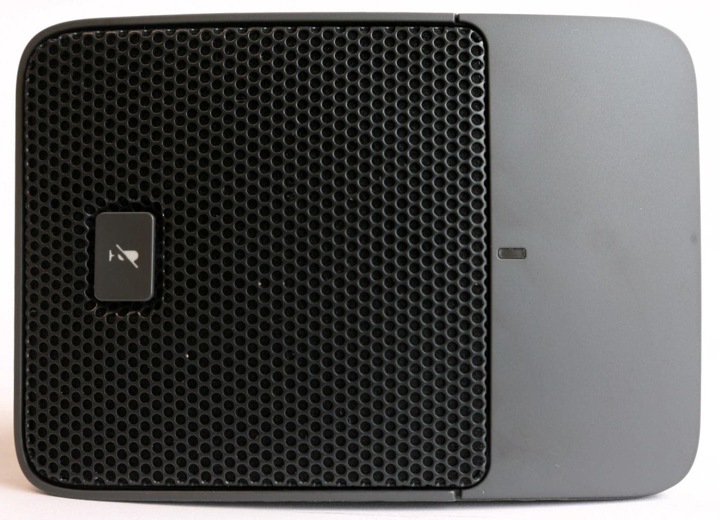
Click to zoom
Application Details
- Equipment Class
- PUB - Part 15 Unlicensed PCS Base Station
- Date of Grant
- Jul 07, 2013
- Application Purpose
- Original Equipment
- Date of Application
- Jul 04, 2013
- Equipment Note
- CISCO VoIP Conference Phone Wireless Microphone
- Frequency Range
- 1921.53600000 - 1928.44800000
- Company
- Cisco Systems Inc
- Country
- United States
Documents & Files
Document Text
Text extracted from the exhibit documents filed with the FCC. Open a document above to read the original.
Users Manual
Americas Headquarters: Cisco Systems, Inc., 170 West Tasman Drive, San Jose, CA 95134-1706 USA Regulatory Compliance and Safety Information for Cisco Unified IP Phones This document provides international agency compliance, safety, and statutory information for Cisco Unified IP Phones. Contents This document contains the following sections: •Translated Safety Warnings, page 2 •Japanese Electric Appliance and Radio Laws, page 28 •Battery Safety Notices, page 28 •Using External Devices with Your Cisco Unified IP Phone, page 32 •European Directives, page 33 •Compliance and Safety Information, page 35 •Obtaining Documentation and Submitting a Service Request, page 44 2 Regulatory Compliance and Safety Information for Cisco Unified IP Phones Translated Safety Warnings This section repeats in multiple languages the basic warnings appropriate for Cisco Unified IP Phones. Statement 1071—Warning Definition WarningIMPORTANT SAFETY INSTRUCTIONS This warning symbol means danger. You are in a situation that could cause bodily injury. Before you work on any equipment, be aware of the hazards involved with electrical circuitry and be familiar with standard practices for preventing accidents. Use the statement number provided at the end of each warning to locate its translation in the translated safety warnings that accompanied this device. Statement 1071 SAVE THESE INSTRUCTIONS Waarschuwing BELANGRIJKE VEILIGHEIDSINSTRUCTIES Dit waarschuwingssymbool betekent gevaar. U verkeert in een situatie die lichamelijk letsel kan veroorzaken. Voordat u aan enige apparatuur gaat werken, dient u zich bewust te zijn van de bij elektrische schakelingen betrokken risico's en dient u op de hoogte te zijn van de standaard praktijken om ongelukken te voorkomen. Gebruik het nummer van de verklaring onderaan de waarschuwing als u een vertaling van de waarschuwing die bij het apparaat wordt geleverd, wilt raadplegen. BEWAAR DEZE INSTRUCTIES Va ro i t u s TÄRKEITÄ TURVALLISUUSOHJEITA Tämä varoitusmerkki merkitsee vaaraa. Tilanne voi aiheuttaa ruumiillisia vammoja. Ennen kuin käsittelet laitteistoa, huomioi sähköpiirien käsittelemiseen liittyvät riskit ja tutustu onnettomuuksien yleisiin ehkäisytapoihin. Turvallisuusvaroitusten käännökset löytyvät laitteen mukana toimitettujen käännettyjen turvallisuusvaroitusten joukosta varoitusten lopussa näkyvien lausuntonumeroiden avulla. SÄILYTÄ NÄMÄ OHJEET Attention IMPORTANTES INFORMATIONS DE SÉCURITÉ Ce symbole d'avertissement indique un danger. Vous vous trouvez dans une situation pouvant entraîner des blessures ou des dommages corporels. Avant de travailler sur un équipement, soyez conscient des dangers liés aux circuits électriques et familiarisez-vous avec les procédures couramment utilisées pour éviter les accidents. Pour prendre connaissance des traductions des avertissements figurant dans les consignes de sécurité traduites qui accompagnent cet appareil, référez-vous au numéro de l'instruction situé à la fin de chaque avertissement. CONSERVEZ CES INFORMATIONS 3 Regulatory Compliance and Safety Information for Cisco Unified IP Phones Warnung WICHTIGE SICHERHEITSHINWEISE Dieses Warnsymbol bedeutet Gefahr. Sie befinden sich in einer Situation, die zu Verletzungen führen kann. Machen Sie sich vor der Arbeit mit Geräten mit den Gefahren elektrischer Schaltungen und den üblichen Verfahren zur Vorbeugung vor Unfällen vertraut. Suchen Sie mit der am Ende jeder Warnung angegebenen Anweisungsnummer nach der jeweiligen Übersetzung in den übersetzten Sicherheitshinweisen, die zusammen mit diesem Gerät ausgeliefert wurden. BEWAHREN SIE DIESE HINWEISE GUT AUF. Avvertenza IMPORTANTI ISTRUZIONI SULLA SICUREZZA Questo simbolo di avvertenza indica un pericolo. La situazione potrebbe causare infortuni alle persone. Prima di intervenire su qualsiasi apparecchiatura, occorre essere al corrente dei pericoli relativi ai circuiti elettrici e conoscere le procedure standard per la prevenzione di incidenti. Utilizzare il numero di istruzione presente alla fine di ciascuna avvertenza per individuare le traduzioni delle avvertenze riportate in questo documento. CONSERVARE QUESTE ISTRUZIONI Advarsel VIKTIGE SIKKERHETSINSTRUKSJONER Dette advarselssymbolet betyr fare. Du er i en situasjon som kan føre til skade på person. Før du begynner å arbeide med noe av utstyret, må du være oppmerksom på farene forbundet med elektriske kretser, og kjenne til standardprosedyrer for å forhindre ulykker. Bruk nummeret i slutten av hver advarsel for å finne oversettelsen i de oversatte sikkerhetsadvarslene som fulgte med denne enheten. TA VARE PÅ DISSE INSTRUKSJONENE Aviso INSTRUÇÕES IMPORTANTES DE SEGURANÇA Este símbolo de aviso significa perigo. Você está em uma situação que poderá ser causadora de lesões corporais. Antes de iniciar a utilização de qualquer equipamento, tenha conhecimento dos perigos envolvidos no manuseio de circuitos elétricos e familiarize-se com as práticas habituais de prevenção de acidentes. Utilize o número da instrução fornecido ao final de cada aviso para localizar sua tradução nos avisos de segurança traduzidos que acompanham este dispositivo. GUARDE ESTAS INSTRUÇÕES ¡Advertencia! INSTRUCCIONES IMPORTANTES DE SEGURIDAD Este símbolo de aviso indica peligro. Existe riesgo para su integridad física. Antes de manipular cualquier equipo, considere los riesgos de la corriente eléctrica y familiarícese con los procedimientos estándar de prevención de accidentes. Al final de cada advertencia encontrará el número que le ayudará a encontrar el texto traducido en el apartado de traducciones que acompaña a este dispositivo. GUARDE ESTAS INSTRUCCIONES 4 Regulatory Compliance and Safety Information for Cisco Unified IP Phones Va r n i n g ! VIKTIGA SÄKERHETSANVISNINGAR Denna varningssignal signalerar fara. Du befinner dig i en situation som kan leda till personskada. Innan du utför arbete på någon utrustning måste du vara medveten om farorna med elkretsar och känna till vanliga förfaranden för att förebygga …
Text truncated - open the document above for the full version.
Users Manual
Cisco Unified IP Phone 8831 User Guide for Cisco Unified Communications Manager 9.3 First Published: April15, 2013 Americas Headquarters Cisco Systems, Inc. 170 West Tasman Drive San Jose, CA 95134-1706 USA http://www.cisco.com Tel: 408 526-4000 800 553-NETS (6387) Fax: 408 527-0883 THE SPECIFICATIONSANDINFORMATIONREGARDINGTHE PRODUCTSIN THISMANUALARE SUBJECTTO CHANGEWITHOUTNOTICE.ALL STATEMENTS, INFORMATION,ANDRECOMMENDATIONSIN THISMANUALARE BELIEVEDTO BE ACCURATE BUT ARE PRESENTEDWITHOUTWARRANTYOF ANYKIND, EXPRESSOR IMPLIED.USERSMUSTTAKEFULLRESPONSIBILITYFOR THEIRAPPLICATIONOF ANYPRODUCTS. THE SOFTWARE LICENSEANDLIMITEDWARRANTYFOR THE ACCOMPANYINGPRODUCTARE SET FORTH IN THE INFORMATIONPACKETTHAT SHIPPEDWITH THE PRODUCTANDARE INCORPORATED HEREINBY THISREFERENCE.IF YOUARE UNABLETO LOCATE THE SOFTWARE LICENSEOR LIMITEDWARRANTY, CONTACT YOURCISCOREPRESENTATIVEFOR A COPY. The followinginformationis for FCC complianceof ClassA devices:This equipmenthas been testedand foundto complywith the limitsfor a ClassA digitaldevice,pursuantto part 15 of the FCC rules.Theselimitsare designedto providereasonableprotectionagainstharmfulinterferencewhenthe equipmentis operatedin a commercialenvironment.This equipment generates,uses, and can radiateradio-frequencyenergy and, if not installedand used in accordancewith the instructionmanual,may causeharmfulinterferenceto radiocommunications. Operationof this equipmentin a residentialarea is likelyto causeharmfulinterference,in whichcase userswill be requiredto correctthe interferenceat their own expense. The followinginformationis for FCC complianceof ClassB devices:This equipmenthas been testedand foundto complywith the limitsfor a ClassB digitaldevice,pursuantto part 15 of the FCC rules.Theselimitsare designedto providereasonableprotectionagainstharmfulinterferencein a residentialinstallation.This equipmentgenerates,uses and can radiateradio frequencyenergy and, if not installedand used in accordancewith the instructions,may causeharmfulinterferenceto radio communications.However, there is no guaranteethat interference will not occurin a particularinstallation.If the equipmentcausesinterferenceto radioor televisionreception,whichcan be determinedby turningthe equipmentoff and on, usersare encouragedto try to correctthe interferenceby usingone or moreof the followingmeasures: • Reorientor relocatethe receivingantenna. • Increasethe separationbetweenthe equipmentand receiver. • Connectthe equipmentinto an outleton a circuitdifferentfrom that to whichthe receiveris connected. • Consultthe dealeror an experiencedradio/TVtechnicianfor help. Modificationsto this productnot authorizedby Ciscocouldvoid the FCC approvaland negateyour authorityto operatethe product The Ciscoimplementationof TCP headercompressionis an adaptationof a programdevelopedby the Universityof California,Berkeley(UCB)as part of UCB’s publicdomainversion of the UNIXoperatingsystem.All rightsreserved.Copyright © 1981,Regentsof the Universityof California. NOTWITHSTANDINGANYOTHERWARRANTYHEREIN,ALL DOCUMENTFILESANDSOFTWARE OF THESESUPPLIERSARE PROVIDED"AS IS" WITHALL FAULTS. CISCOANDTHE ABOVE-NAMEDSUPPLIERSDISCLAIMALL WARRANTIES,EXPRESSEDOR IMPLIED,INCLUDING,WITHOUTLIMITATION,THOSEOF MERCHANTABILITY, FITNESSFOR A PARTICULARPURPOSEANDNONINFRINGEMENTOR ARISINGFROMA COURSEOF DEALING,USAGE,OR TRADEPRACTICE. IN NO EVENTSHALLCISCOOR ITS SUPPLIERSBE LIABLEFOR ANYINDIRECT, SPECIAL,CONSEQUENTIAL,OR INCIDENTAL DAMAGES,INCLUDING,WITHOUT LIMITATION,LOSTPROFITSOR LOSSOR DAMAGETO DATA ARISINGOUTOF THE USE OR INABILITYTO USE THISMANUAL,EVENIF CISCOOR ITS SUPPLIERS HAVE BEENADVISEDOF THE POSSIBILITYOF SUCHDAMAGES. Any InternetProtocol(IP) addressesused in this documentare not intendedto be actualaddresses.Any examples,commanddisplayoutput,and figuresincludedin the documentare shown for illustrativepurposesonly. Any use of actualIP addressesin illustrativecontentis unintentionaland coincidental. Ciscoand the Ciscologo are trademarksor registeredtrademarksof Ciscoand/orits affiliatesin the U.S. and othercountries.To view a list of Ciscotrademarks,go to this URL:http:// www.cisco.com/go/trademarks. Third-partytrademarksmentionedare the propertyof their respectiveowners.The use of the wordpartnerdoes not implya partnership relationshipbetweenCiscoand any othercompany. (1110R) © 2013 CiscoSystems,Inc. All rightsreserved. CONTENTS CHAPTER 1 Preface1 Introduction1 AdditionalInformation2 Safetyand PerformanceInformation2 Poweroutage2 Externaldevices2 Ciscoproductsecurityoverview3 AccessibilityFeatures3 CHAPTER 2 Features of your Cisco UnifiedIP Phone5 Buttonsand hardware5 DisplayControlUnit6 SoundBase7 Wirelessextensionmicrophoneand charger9 Wired extensionmicrophonekit11 Phonescreen12 Phonescreencleaning14 Phoneconnections14 Installferritebead16 Removeferritebead17 GeneralIP Phoneinformation17 Power-savingmode17 Featureavailability18 CHAPTER 3 Applications19 Services19 AccessServices19 Call History19 Cisco Unified IP Phone 8831 User Guide for Cisco Unified Communications Manager 9.3 iii View call history20 View call recorddetails20 Dial from Call History21 Edit phonenumber21 Clearcall history21 Deletecall record22 Preferences22 Ringtones22 ChangeRingtone22 Contrast23 AdjustContrast23 LinkedMode23 Link IP Phones24 IP PhoneInformation24 AdministratorSettings25 CHAPTER 4 Contacts27 CorporateDirectory27 Dial Contactfrom Search27 Dial Contactfrom Searchduringan activecall28 PersonalDirectory28 PersonalDirectoryoptions29 Sign In and Out of PersonalDirectory29 Add PersonalDirectoryentry30 Searchfor entryin PersonalDirectory30 Dial numberfrom PersonalDirectory31 DeletePersonalDirectoryentry31 Edit PersonalDirectoryentry31 Fast Dial codeswith PersonalDirectory32 Assignfast dial code to PAB from the phone32 Assignfast dial code to PAB from User Optionsweb page32 Placecall usingfast dial code33 Deletefast dial code33 CHAPTER 5 Messages35 Cisco Unified IP Phone 8831 User Guide for Cisco Unified Communications Manager 9.3 iv Conten…
Text truncated - open the document above for the full version.
Cover Letter(s)
Cisco Systems, Inc. 170 West Tasman Drive San Jose, CA 95134-‐1706 Phone 408 526-‐4000 Fax: 408 526 –4100 http://www.cisco.com April 22, 2013 Federal Communications Commission Office of Engineering and Technology Equipment Authorization division 7345 Oakland Mills Road Columbia, Maryland 21046 Subject: Confidentiality request for FCC ID LDKMICWR0776 and IC ID 2461B-MICWR0776 Pursuant to FCC 47 CRF 0.457(d) and 0.459 and IC RSP-100, Section 10, the applicant requests that apart of the subject FCC application be held confidential. Type of Confidentiality Requested Exhibit Short Term n Permanent Block Diagrams n Short Term Permanent 1 Internal Photos Short Term n Permanent Operation Description/Theory of Operation Short Term n Permanent Parts List & Placement/BOM Short Term n Permanent Tune-Up Procedure Short Term n Permanent Schematics n Short Term Permanent User Guide Permanent Confidentiality: The applicant requests the exhibits listed above as permanently confidential be permanently withheld from public review due to materials that contain trade secrets and proprietary information not customarily released to the public. Short-Term Confidentiality: The applicant requests the exhibits selected above as short term confidential be withheld from public view for a period of _45 days from the date of the Grant of Equipment Authorization and prior to marketing. This is to avoid premature release of sensitive information prior to marketing or release of the product to the public. Applicant is also aware that they are responsible to notify ACB in the event information regarding the product or the product is made available to the public. ACB will then release the documents listed above for public disclosure pursuant to FCC Public Notice DA 04-1705. Sincerely, Kenny Wee Manager, Engineering Cisco Systems, Inc.
External Photos
Wireless Mic front Wireless mic rear Wireless Mic Right hand side Wireless Mic left hand side Wireless mic top Wireless mic, base with battery cover in place Wireless mic, base with battery cover removed
ID Label/Location Info
Dimensions are shown in imperial (metric) Tolerances unless otherwise specified are: Dimensions Tolerance: P2C Tolerance: ± 0.25mm” ± 0.25mm” SCALE:1:1 SHEET:1 of 1 UNIT: INCHES ORIGINATIONDATECHECK BYDATE Rev.DescriptionECN Chan S. WM REF. No. Red Line is cut line Title:________________________________Date:______________ Approved By:___________________________________________ DELIVERY TIME CAN ONLY BE MET WITH YOUR COOPERATION. PLEASE ENSURE THE ARTWORK PROOF IS CHECKED CAREFULLY FOR LAYOUT, WORDING, SPELLING, SIZE, COLOR, ETC., THEN, RETURNED WITHIN 24 HOURS, TO ENSURE DELIVERY SCHEDULES ARE MET. THE COLORS DISPLAYED ON THIS PROOF MAY NOT BE ACCURATE; REFER TO PMS OR CISCO COLOR BOOK REFERENCES STATED FOR TRUE REPRESENTATION. IMPORTANT 03/12/13 LABEL COME OFF THIS END Perforation line between each set 57.50mm 25.00mm 45.00mm 11.00mm 49.00mm 19.00mm R 1.00mm R 2.00mm LABEL FINISHED COPY: NOTES: A) Material PL339-J1(Worldmark)Mat Ref: Ribbon: LABELS/TILE: TILES/PACK: LABELS/PACK: Matrix Strip:YN B) COLORSC) FONTS 1)1) 2) 2) 3) 4) 5) 6) 7) 8) 3) 4) 5) 6) 7) 8) Graphics Grey( Vanish Custom Black Background DPW7424 ( GREY) DPW7424) DWG/PN: AW#: DESC: CP-MIC-WRLS-S-US= CUST. NAME: LISA/JON Artwork proof. #5 ARTWORK- POD BARCODE DISPLAYED HERE ARE DEMO PURPOSES ONLY. 2.54mm(X2) 62.57mm 1.69mm KISSCUT LINE WEBB WIDTH LINE 1000744-00(ref.Revolab blank) 56-19863-01 REV.A0 (US) CUS FCC ID:LDKMICWR0776 IC:2461B-MICWR0776 74-11135-01 74-11135-01 PID VID: CP-MIC-WRLS-S-US=V01 CP-MIC-WRLS-S-US FCH12345678 SN: FCH12345678 cn Made in China www.cisco.com TAN: 中造 Model: Cisco IP Phone CP-MIC-WRLS-S-US= 型号/Modèle: Cisco IP电话CP-MIC-WRLS-S-US= Manufacturer(制造商/Fabricant): Cisco Systems, Inc. NOTE: INSIDE BOX ARE DYNAMIC FIELDS GET ENTRIES BY CM SITE.SEE BOM PROVIDED BY CISCO.
ID Label/Location Info
Cisco Systems, Inc. 170 West Tasman Drive San Jose, CA 95134-‐1706 Phone 408 526-‐4000 Fax: 408 526 –4100 http://www.cisco.com Label Location Diagram CP-MIC-WRLS-S-US
Internal Photos
PCB Component side PCB Solder side TX Antenna
RF Exposure Info
Test Number: 386-12R5 Issue Date: 6/12/2013 Page 56 of 65 6. Measurement Data (continued) 6.12. Public Exposure to Radio Frequency Energy Levels (1.1307 (b)(1)) RSS-GEN 5.5, RSS 102 6.12.1. MPE Power Density Table Power Density Channel MPE Distance (cm) DUT Output Power (dBm) DUT Antenna Gain (dBi) (mW/cm2) (W/m2) Limit (mW/cm2) Result (1) (2) (3) (4) (5) TX4 20.0 20.03 0.37 0.022 0.218 1 Compliant TX2 20.0 19.86 0.44 0.021 0.213 1 Compliant TX0 20.0 19.69 0.31 0.020 0.199 1 Compliant PD = OP + AG (4 x π x d²) PD = Power Density OP = DUT Output Power (dBm) AG = Antenna Gain (dBi) D = MPE Distance 1. Reference CFR 2.1093(b): For purposes of this section, a portable device is defined as a transmitting device designed to be used so that the radiating structure(s) of the device is/are within 2.5 centimeters of the body of the user. 2. Section 6.3 of this test report. 3. Data determined by comparing Conducted and Radiated Output Power. 4. Power density is calculated from conducted power output measurement and antenna gain. 5. Reference CFR 1.1310, Table 1: Limits for Maximum Permissible Exposure (MPE), Section (B): Limits for General Population/Uncontrolled Exposure. Compliance Worldwide, Inc. - 357 Main Street - Sandown, NH 03873 (603) 887 3903 Fax 887 6445 http://www.cw-inc.com Test Number: 386-12R5 Issue Date: 6/12/2013 Page 57 of 65 Compliance Worldwide, Inc. - 357 Main Street - Sandown, NH 03873 (603) 887 3903 Fax 887 6445 http://www.cw-inc.com 6. Measurement Data (continued) 6.11. Public Exposure to Radio Frequency Energy Levels (1.1307 (b)(1)) RSS-GEN 5.5, RSS 102 cont. 6.12.2. MPE Time Averaged Power Table Frequency DUT Output Power DUT Antenna Gain Calculated Output Power Time Averaged Power Limit Result Channel (MHz) (dBm) (dBi) (mW) (mW) (mW) TX4 1921.536 20.03 0.37 109.65 4.25 100.00 Compliant TX2 1924.992 19.86 0.44 107.15 4.15 100.00 Compliant TX0 1928.448 19.69 0.31 100.00 3.88 100.00 Compliant NOTE: Although the peak power is over the general exposure limit for RSS-102, the time averaged power is very small for DECT technology. In this case a nominal frame width of 387.5 μS repeating every 10 mS, and therefore is compliant with the general exposure requirements defined in RSS-102 Section 2.5.1. The reduction in power is calculated by 10 * LOG (0.3875 / 10) or -14.12 dB. In a case where a user would place this product on their body (e.g. in their pocket). This device is excluded from SAR testing per KDB 447498 D01 v05 section 4.3.1 1) page 10. Using the formula [(max. Power of channel, including tune up tolerance, mW) / (min. Test separation distance, mm)] * [f (GHz)] ^ 0.5 <=3.0, the number is calculated to be [4.25 mW / 5 mm] * [1.93] ^ 0.5 = 1.2. This value is less than the 3.0 to allow the device to be excluded from SAR testing for a body worn device. RSS-102 Section 2.5 and 2.5.1 Requirements: All transmitters are exempt from routine SAR and RF exposure evaluations provided that output power complies with the power levels of sections 2.5.1 or 2.5.2. If the equipment under test (EUT) meets the requirements of sections 2.5.1 or 2.5.2, applicants are only required to submit a properly signed declaration of compliance (see Annex C). SAR evaluation is required if the separation distance between the user and the radiating element of the device is less than or equal to 20 cm, except when the device operates as follows: • above 1 GHz and up to 2.2 GHz inclusively, and with output power (i.e. the higher of the conducted or radiated (e.i.r.p.) source-based, time-averaged output power) that is less than or equal to 100 mW for general public use and 500 mW for controlled use
Test Report
COMPLIANCE WORLDWIDE INC. TEST REPORT 386-12R5 In Accordance with the Requirements of Industry Canada RSS 213, Issue 2, December 2005 2 GHz License-exempt Personal Communications Service Devices (LE-PCS) Federal Communications Commission 47 CFR Part 15, Subpart D Technical Requirements for Unlicensed Personal Communication Systems (UPCS) Issued to CISCO Systems, Inc. 170 West Tasman Drive San Jose, CA 95134 For the CISCO Wireless Microphone Model Number: CP-MIC-WRLS-S-US FCC ID: LDKMICWR0776 IC: 2461B-MICWR0776 Report Issued on June 12, 2013 Tested By This test report shall not be reproduced, except in full, without written permission from Compliance Worldwide, Inc. Compliance Worldwide, Inc. - 357 Main Street - Sandown, NH 03873 (603) 887 3903 Fax 887 6445 http://www.complianceworldwide.com Test Number: 386-12R5 Issue Date: 6/12/2013 Page 2 of 65 Compliance Worldwide, Inc. - 357 Main Street - Sandown, NH 03873 (603) 887 3903 Fax 887 6445 http://www.cw-inc.com Table of Contents 1. Scope..................................................................................................................................................................3 2. Product Details....................................................................................................................................................3 2.1. Manufacturer............................................................................................................................................. 3 2.2. Model Number .......................................................................................................................................... 3 2.3. Serial Number ........................................................................................................................................... 3 2.4. Description ................................................................................................................................................ 3 2.5. Power Source ........................................................................................................................................... 3 2.6. Hardware Revision.................................................................................................................................... 3 2.7. Software Revision ..................................................................................................................................... 3 2.8. Modulation Type ....................................................................................................................................... 3 2.9. Operating Frequency ................................................................................................................................ 3 2.10. Emission Designator............................................................................................................................... 3 2.11. EMC Modifications .................................................................................................................................. 3 3. Product Configuration .........................................................................................................................................3 3.1. Operational Characteristics & Software .................................................................................................... 3 3.2. EUT Hardware .......................................................................................................................................... 3 3.3. EUT CablesTransducers........................................................................................................................... 3 3.4. Support Equipment................................................................................................................................... 4 3.5. EUT Diagram ............................................................................................................................................ 4 3.6. Test Setup Diagram .................................................................................................................................. 5 4. Measurements Parameters.................................................................................................................................5 4.1. Measurement Equipment Used to Perform Test ....................................................................................... 5 4.2. Measurement & Equipment Setup ............................................................................................................ 6 4.3. Measurement Procedure .......................................................................................................................... 6 4.4. Choice of Operating Frequencies ............................................................................................................. 6 5. Measurement Summary......................................................................................................................................7 6. Measurement Data .............................................................................................................................................8 6.1. Antenna Requirement ............................................................................................................................... 8 6.2. Type of Modulation and Access Protocol.................................................................................................. 8 6.3. Peak Transmit Power................................................................................................................................ 9 6.4. Emission Bandwidth................................................................................................................................ 13 6.5. Spurious Emissions at the antenna terminals ......................................................................................... 16 6.6. Radia…
Text truncated - open the document above for the full version.
Test Setup Photos
Test Number: 386-12R5 Issue Date: 6/12/2013 7. Test Images 7.1. Radiated Emissions (Front) Page 58 of 65 Compliance Worldwide, Inc. - 357 Main Street - Sandown, NH 03873 (603) 887 3903 Fax 887 6445 http://www.cw-inc.com Test Number: 386-12R5 Issue Date: 6/12/2013 7. Test Images 7.2. Radiated Emissions - 30 MHz – 1 GHz (Rear) Page 59 of 65 Compliance Worldwide, Inc. - 357 Main Street - Sandown, NH 03873 (603) 887 3903 Fax 887 6445 http://www.cw-inc.com Test Number: 386-12R5 Issue Date: 6/12/2013 7. Test Images 7.3. Radiated Emissions - Above 1 GHz (Rear) Page 60 of 65 Compliance Worldwide, Inc. - 357 Main Street - Sandown, NH 03873 (603) 887 3903 Fax 887 6445 http://www.cw-inc.com Test Number: 386-12R5 Issue Date: 6/12/2013 7. Test Images 7.4. Radiated Emissions – Below 30 MHz (Rear) Page 61 of 65 Compliance Worldwide, Inc. - 357 Main Street - Sandown, NH 03873 (603) 887 3903 Fax 887 6445 http://www.cw-inc.com Test Number: 386-12R5 Issue Date: 6/12/2013 7. Test Images 7.5. Conducted Emissions - Front Page 62 of 65 Compliance Worldwide, Inc. - 357 Main Street - Sandown, NH 03873 (603) 887 3903 Fax 887 6445 http://www.cw-inc.com Test Number: 386-12R5 Issue Date: 6/12/2013 7. Test Images 7.6. Conducted Emissions - Rear Page 63 of 65 Compliance Worldwide, Inc. - 357 Main Street - Sandown, NH 03873 (603) 887 3903 Fax 887 6445 http://www.cw-inc.com Test Number: 386-12R5 Issue Date: 6/12/2013 7. Test Images 7.7. Antenna Port Conducted Measurements Page 64 of 65 Compliance Worldwide, Inc. - 357 Main Street - Sandown, NH 03873 (603) 887 3903 Fax 887 6445 http://www.cw-inc.com
Contact Information
Applicant
Samuel Kim(Manager, Engineering)
Technical Contact
Cisco Systems, Inc.Vipul Jain
[email protected]4085255796
170 West Tasman Drive · San Jose, California · United States
Non-Technical Contact
Cisco Systems, Inc.Lisa Bevington
[email protected]4088539174
Test Firm
Compliance Worldwide, Inc.Deb Bourbeau
Technical Specifications
| # | Rule Parts | Frequency Range | Power Output |
|---|---|---|---|
| 1 | 15D | 1.92 GHz - 1.93 GHz | 101.00 mW |
Other Applications from Cisco Systems Inc

LDKJ98213058
May 25, 2026Wireless Phone
Equipment Class
DSS - Part 15 Spread Spectrum TransmitterLDKIW9165E
Aug 20, 2024Wi-Fi 6E Outdoor Access Point
Equipment Class
6SD - 15E 6 GHz Standard Power Access PointLDKIW9165DH
Aug 05, 2024Wi-Fi 6E Outdoor Access Point
Equipment Class
6SD - 15E 6 GHz Standard Power Access PointLDKUSBC2857
Jul 22, 2024Cisco Headset USB-C Adapter
Equipment Class
DSS - Part 15 Spread Spectrum TransmitterLDKESPRD2922
May 09, 2024UC Phone
Equipment Class
NII - Unlicensed National Information Infrastructure TX