LDKWRP501156Dual Band Wireless Broadband Router
Cisco Systems Inc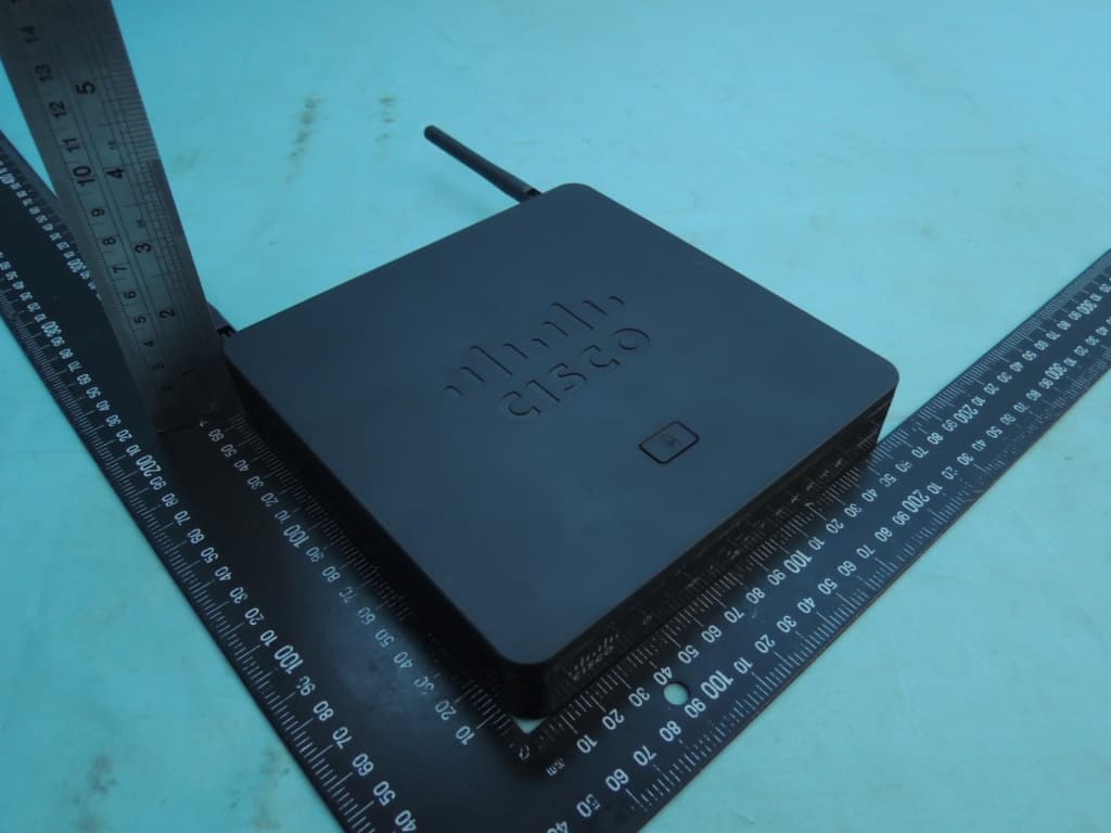
Click to zoom
Application Details
- Equipment Class
- DTS - Digital Transmission System
- Date of Grant
- Jan 27, 2015
- Application Purpose
- Original Equipment
- Date of Application
- Jan 26, 2015
- Equipment Note
- Dual Band Wireless Broadband Router
- Frequency Range
- 2422.00000000 - 2452.00000000
- Company
- Cisco Systems Inc
- Country
- United States
Documents & Files
Document Text
Text extracted from the exhibit documents filed with the FCC. Open a document above to read the original.
Users Manual
REVIEW DRAFT #1—CISCO CONFIDENTIAL Cisco Systems, Inc. www.cisco.com Cisco has more than 200 offices worldwide. Addresses, phone numbers, and fax numbers are listed on the Cisco website at www.cisco.com/go/offices. Cisco WRP500 Administration Guide Wireless-G Broadband Router with 2 Phone Ports and Built-In Analog Telephone Adapter December 23, 2014 Last Updated: December 23, 2014 ADMINISTRATION GUIDE REVIEW DRAFT #1—CISCO CONFIDENTIAL THE SPECIFICATIONS AND INFORMATION REGARDING THE PRODUCTS IN THIS MANUAL ARE SUBJECT TO CHANGE WITHOUT NOTICE. ALL STATEMENTS, INFORMATION, AND RECOMMENDATIONS IN THIS MANUAL ARE BELIEVED TO BE ACCURATE BUT ARE PRESENTED WITHOUT WARRANTY OF ANY KIND, EXPRESS OR IMPLIED. USERS MUST TAKE FULL RESPONSIBILITY FOR THEIR APPLICATION OF ANY PRODUCTS. THE SOFTWARE LICENSE AND LIMITED WARRANTY FOR THE ACCOMPANYING PRODUCT ARE SET FORTH IN THE INFORMATION PACKET THAT SHIPPED WITH THE PRODUCT AND ARE INCORPORATED HEREIN BY THIS REFERENCE. IF YOU ARE UNABLE TO LOCATE THE SOFTWARE LICENSE OR LIMITED WARRANTY, CONTACT YOUR CISCO REPRESENTATIVE FOR A COPY. The following information is for FCC compliance of Class A devices: This equipment has been tested and found to comply with the limits for a Class A digital device, pursuant to part 15 of the FCC rules. These limits are designed to provide reasonable protection against harmful interference when the equipment is operated in a commercial environment. This equipment generates, uses, and can radiate radio-frequency energy and, if not installed and used in accordance with the instruction manual, may cause harmful interference to radio communications. Operation of this equipment in a residential area is likely to cause harmful interference, in which case users will be required to correct the interference at their own expense. The following information is for FCC compliance of Class B devices: This equipment has been tested and found to comply with the limits for a Class B digital device, pursuant to part 15 of the FCC rules. These limits are designed to provide reasonable protection against harmful interference in a residential installation. This equipment generates, uses and can radiate radio frequency energy and, if not installed and used in accordance with the instructions, may cause harmful interference to radio communications. However, there is no guarantee that interference will not occur in a particular installation. If the equipment causes interference to radio or television reception, which can be determined by turning the equipment off and on, users are encouraged to try to correct the interference by using one or more of the following measures: •Reorient or relocate the receiving antenna. •Increase the separation between the equipment and receiver. •Connect the equipment into an outlet on a circuit different from that to which the receiver is connected. •Consult the dealer or an experienced radio/TV technician for help. Modifications to this product not authorized by Cisco could void the FCC approval and negate your authority to operate the product. The Cisco implementation of TCP header compression is an adaptation of a program developed by the University of California, Berkeley (UCB) as part of UCB’s public domain version of the UNIX operating system. All rights reserved. Copyright © 1981, Regents of the University of California. NOTWITHSTANDING ANY OTHER WARRANTY HEREIN, ALL DOCUMENT FILES AND SOFTWARE OF THESE SUPPLIERS ARE PROVIDED “AS IS” WITH ALL FAULTS. CISCO AND THE ABOVE-NAMED SUPPLIERS DISCLAIM ALL WARRANTIES, EXPRESSED OR IMPLIED, INCLUDING, WITHOUT LIMITATION, THOSE OF MERCHANTABILITY, FITNESS FOR A PARTICULAR PURPOSE AND NONINFRINGEMENT OR ARISING FROM A COURSE OF DEALING, USAGE, OR TRADE PRACTICE. IN NO EVENT SHALL CISCO OR ITS SUPPLIERS BE LIABLE FOR ANY INDIRECT, SPECIAL, CONSEQUENTIAL, OR INCIDENTAL DAMAGES, INCLUDING, WITHOUT LIMITATION, LOST PROFITS OR LOSS OR DAMAGE TO DATA ARISING OUT OF THE USE OR INABILITY TO USE THIS MANUAL, EVEN IF CISCO OR ITS SUPPLIERS HAVE BEEN ADVISED OF THE POSSIBILITY OF SUCH DAMAGES. Cisco and the Cisco logo are trademarks or registered trademarks of Cisco and/or its affiliates in the U.S. and other countries. To view a list of Cisco trademarks, go to this URL: www.cisco.com/go/trademarks. Third-party trademarks mentioned are the property of their respective owners. The use of the word partner does not imply a partnership relationship between Cisco and any other company. (1110R) Any Internet Protocol (IP) addresses and phone numbers used in this document are not intended to be actual addresses and phone numbers. Any examples, command display output, network topology diagrams, and other figures included in the document are shown for illustrative purposes only. Any use of actual IP addresses or phone numbers in illustrative content is unintentional and coincidental. © 2015 Cisco Systems, Inc. All rights reserved. iii Cisco WRP500 Administration Guide REVIEW DRAFT #1—CISCO CONFIDENTIAL CONTENTS CHAPTER 1Product Overview and Deployment Guidelines 1-1 WRP500 Features and Benefits 1-2 Deployment Models 1-3 WRP500 Deployment in a Basic Network 1-3 WRP500 Deployment with a Wireless Guest Network 1-4 WRP500 Deployment with Mobile Broadband 1-5 Mobile Office That Uses the Mobile Network for Internet Access 1-5 Basic Office Deployment That Uses the Mobile Network as a Backup Connection 1-6 Local Area Network Guidelines 1-6 Power, Cabling, and Telephone Lines 1-6 Basic Services and Equipment 1-7 Special Requirements for Voice Deployments 1-7 Bandwidth for Voice Deployments 1-7 NAT Mapping for Voice over IP Deployments 1-9 Local Area Network Design for Voice Deployments 1-9 WRP500 Maintenance Operations 1-10 Remote Provisioning 1-11 Upgrade URL 1-11 Resync URL 1-12 Reboot URL 1-12 Configuration Profile 1-12 XML Format 1-13 Binary Format 1-13 CHAPTER 2Configure Your System for ITSP Interoperability 2-1 Configure NAT Mapping 2-1 Configure NAT Mapping with a Static IP Address 2-1 …
Text truncated - open the document above for the full version.
Users Manual
REVIEW DRAFT - CISCO CONFIDENTIAL Regulatory Compliance and Safety Information—Cisco WRP500 Wireless-G Broadband Router with 2 Phone Ports Information sur la réglementation de la conformité et de sécurité—Cisco WRP500 Wireless-G Broadband Router with 2 Phone Ports First Published: December15, 2014 Première publication: 15 Décembre2014 Last Updated: December19, 2014 Dernière mise à jour: 19 Décembre2014 Cisco Systems, Inc. www.cisco.com Cisco has more than 200 offices worldwide. Addresses, phone numbers, and fax numbers are listed on the Cisco website at www.cisco.com/go/offices. Cisco possède plus de 200 bureaux dans le monde entier. Adresses, numéros de téléphone et numéros de fax sont répertoriés sur le site Web de Cisco à l' www.cisco.com/go/offices. RCSI Part Number: RCSI-0144 RCSI Numéro de pièce : RCSI-0144 CONTENTS Regulatory Compliance and Safety Information—Cisco WRP500 Wireless-G Broadband Router with 2 Phone Ports1 Gesetzliche Auflagen und Sicherheitshinweise—Cisco WRP500 Wireless-G Broadband Router with 2 Phone Ports9 Cumplimiento de las normas e información de seguridad—Cisco WRP500 Wireless-G Broadband Router with 2 Phone Ports15 Säädösten noudattaminen ja turvallisuustiedot—Cisco WRP500 Wireless-G Broadband Router with 2 Phone Ports23 Informations relatives à la conformité et à la sécurité—Cisco WRP500 Wireless-G Broadband Router with 2 Phone Ports29 A szabályozásnak való megfelelésre és a biztonságra vonatkozó információk—Cisco WRP500 Wireless-G Broadband Router with 2 Phone Ports37 Informazioni sulla conformità alle normative e sulla sicurezza—Cisco WRP500 Wireless-G Broadband Router with 2 Phone Ports43 法規制順守および安全性情報—Cisco WRP500 Wireless-G Broadband Router with 2 Phone Ports49 Informasjon om forskriftsmessig samsvar og sikkerhet—Cisco WRP500 Wireless-G Broadband Router with 2 Phone Ports55 Regelnaleving en veiligheidsinformatie—Cisco WRP500 Wireless-G Broadband Router with 2 Phone Ports61 Regulamentação de Conformidade e Informações de Segurança—Cisco WRP500 Wireless-G Broadband Router with 2 Phone Ports67 Информацияобезопасностиисоблюдениинормативныхтребований—Cisco WRP500 Wireless-G Broadband Router with 2 Phone Ports73 Information om överensstämmelse med regelverk och säkerhetskrav—Cisco WRP500 Wireless-G Broadband Router with 2 Phone Ports79 合规性和安全信息—Cisco WRP500 Wireless-G Broadband Router with 2 Phone Ports85 法規遵循與安全資訊—Cisco WRP500 Wireless-G Broadband Router with 2 Phone Ports91 Съответствиеснормативнатауредбаиинформациязабезопасност—Cisco WRP500 Wireless-G Broadband Router with 2 Phone Ports95 Informace o bezpečnosti a dodržování předpisů—Cisco WRP500 Wireless-G Broadband Router with 2 Phone Ports97 Regulatory Compliance and Safety Information—Cisco WRP500 Wireless-G Broadband Router with 2 Phone Ports iii Overholdelse af lovgivningen og sikkerhedsoplysninger—Cisco WRP500 Wireless-G Broadband Router with 2 Phone Ports101 Συμμόρφωσημετουςκανονισμούςκαιπληροφορίεςασφαλείας—Cisco WRP500 Wireless-G Broadband Router with 2 Phone Ports105 Eeskirjade järgimine ja ohutusteave—Cisco WRP500 Wireless-G Broadband Router with 2 Phone Ports109 reglufylgni og öryggisupplýsingar—Cisco WRP500 Wireless-G Broadband Router with 2 Phone Ports111 reglamentinei atitikties ir saugos informacijai—Cisco WRP500 Wireless-G Broadband Router with 2 Phone Ports113 Atbilstība normatīviem un informācija par drošību—Cisco WRP500 Wireless-G Broadband Router with 2 Phone Ports115 Konformità mar-Regolamenti u Informazzjoni Dwar is-Sigurtà—Cisco WRP500 Wireless-G Broadband Router with 2 Phone Ports117 Informacje o zgodności i bezpieczeństwie—Cisco WRP500 Wireless-G Broadband Router with 2 Phone Ports119 Informaţii referitoare la siguranţăşi conformitatea cu reglementările—Cisco WRP500 Wireless-G Broadband Router with 2 Phone Ports123 Dodržiavanie predpisov a bezpečnostné informácie—Cisco WRP500 Wireless-G Broadband Router with 2 Phone Ports125 규정준수및안전정보—Cisco WRP500 Wireless-G Broadband Router with 2 Phone Ports129 Informacije o skladnosti s predpisi in varnosti—Cisco WRP500 Wireless-G Broadband Router with 2 Phone Ports133 Cisco WRP500 Wireless-G Broadband Router with 2 Phone Portsالتنظيمي—التوافق Regulatory Compliance السلامةومعلومات135 Usklađenost sa propisima i informacije o sigurnosti—Cisco WRP500 Wireless-G Broadband Router with 2 Phone Ports137 Регулаторнаусогласеностибезбедносниинформации—Cisco WRP500 Wireless-G Broadband Router with 2 Phone Ports139 Conformidade regulamentar e informações de segurança—Cisco WRP500 Wireless-G Broadband Router with 2 Phone Ports143 Regulatory Compliance and Safety Information—Cisco WRP500 Wireless-G Broadband Router with 2 Phone Ports iv Contents REVIEW DRAFT - CISCO CONFIDENTIAL CHAPTER 1 Regulatory Compliance and Safety Information—Cisco WRP500 Wireless-G Broadband Router with 2 Phone Ports •Statement19—TN Power Warning,page 2 •Statement157—VCCI Compliancefor Class B Equipment,page 3 •Statement199—Emergency AccessWarning,page 3 •Statement287—DeclarationofConformitytoR&TTEDirective1999/5/ECfortheEuropeanCommunity, Switzerland,Norway, Icelandand Liechtenstein,page 3 •Statement295—Class B Warning for Korea,page 3 •Statement331—Power SupplyInstallationWarning,page 3 •Statement353—This ProductMust be Connected,page 4 •Statement355—TelephoneReceiversProducea MagneticField, page 4 •Statement361—VoIP and Emergency CallingServicesdo not Functionif Power Fails, page 4 •Statement378—Read Wall-MountingInstructionsBeforeInstallation,page 4 •Statement1003—DC Power Disconnection,page 4 •Statement1004—InstallationInstructions,page 5 •Statement1005—CircuitBreaker, page 5 •Statement1019—Main DisconnectingDevice,page 5 •Statement1021—SELV Circuit,page 5 •Statement1030—EquipmentInstallation,page 5 •Statement1040—ProductDisposal,page 5 •Statement1044—Port Connections,page 6 •Statement1071—Warning Definition,page 6 •Statement1072—Shock Hazardfrom Interconnections,page 6 Regulatory Compliance and Safety Information—Cisco WRP500 Wireless-G Broadband Router with 2 Phone Ports 1 •S…
Text truncated - open the document above for the full version.
Attestation Statements
Cisco Systems, Inc. 170 West Tasman Drive San Jose, CA 95134-‐1706 Phone 408 526-‐4000 Fax: 408 526 –4100 http://www.cisco.com Software Security Attestation The channel and frequency bands list in this filing is information when programmed into the NVM will not be accessible and cannot be changed by the end user. The transmitter is approved as a non-‐software defined radio and OEMs and third party system integrators do not have the ability through software to allow configuration controls that would permit the device to operate outside the grant conditions per FCC KDB 594280. Gerard Thorpe Manager Test Development Engineering
Cover Letter(s)
Cisco Systems, Inc. 170 West Tasman Drive San Jose, CA 95134-‐1706 Phone 408 526-‐4000 Fax: 408 526 –4100 http://www.cisco.com Authority to Act as Agent Date: 12/18/2014 American Certification Body, Inc. 6731 Whittier Avenue Suite C110 McLean, VA 22101 To Whom It May Concern: Gerard Thorpe is authorized to act on our behalf, until otherwise notified, for applications to American Certification Body, Inc. (ACB). We certify that we are not subject to denial of federal benefits, that includes FCC benefits, pursuant to Section 5301 of the Anti-Drug Abuse Act of 1988, 21 U.S.C. 862. Further, no party, as defined in 47 CFR 1.2002 (b), to the application is subject to denial of federal benefits, that includes FCC benefits. Thank you, Agency Agreement Expiration Date: _____12/18/2015 By: _ __Gerard Thorpe__ (Signature 1 ) (Print name) Title: _Manager Test Development Engineering__ On behalf of: _Cisco Systems, Inc._ (Company Name) Telephone: _408-527-7097_ .
Cover Letter(s)
Cisco Systems, Inc. 170 West Tasman Drive San Jose, CA 95134-‐1706 Phone 408 526-‐4000 Fax: 408 526 –4100 http://www.cisco.com Request for Confidentiality Date: 12/18/2014 Subject: Confidentiality Request for: IC: 2461L-WRP501156 Pursuant to FCC 47 CRF 0.457(d) and 0.459 and IC RSP-100, Section 10, the applicant requests that a part of the subject FCC application be held confidential. Type of Confidentiality Requested Exhibit Short Term Permanent Block Diagrams Short Term External Photos Short Term Permanent* 1 Internal Photos Short Term Permanent Operation Description/Theory of Operation Short Term Permanent Parts List & Placement/BOM Short Term Permanent Tune-Up Procedure Short Term Permanent Schematics Short Term Permanent* User’s Manual Short Term Permanent Test Set Up Photos Cisco Systems, Inc. has spent substantial effort in developing this product and it is one of the first of its kind in industry. Having the subject information easily available to "competition" would negate the advantage they have achieved by developing this product. Not protecting the details of the design will result in financial hardship. Permanent Confidentiality: The applicant requests the exhibits listed above as permanently confidential be permanently withheld from public review due to materials that contain trade secrets and proprietary information not customarily released to the public. Short-Term Confidentiality: The applicant requests the exhibits selected above as short term confidential be withheld from public view for a period of ___(45) days from the date of the Grant of Equipment Authorization and prior to marketing. This is to avoid premature release of sensitive information prior to marketing or release of the product to the public. Applicant is also aware that they are responsible to notify ACB in the event information regarding the product or the product is made available to the public. ACB will then release the documents listed above for public disclosure pursuant to FCC Public Notice DA 04-1705. NOTE for Industry Canada Applications: The applicant understands that until such time that IC distinguishes between Short Term and Permanent Confidentiality, either type of marked exhibit above will simply be marked Confidential when submitted to IC. Sincerely Steven Lawrence By:_____ ___ Steven Lawrence (Signature/Title) (Print name)
ID Label/Location Info
Cisco Systems, Inc. 170 West Tasman Drive San Jose, CA 95134-‐1706 Phone 408 526-‐4000 Fax: 408 526 –4100 http://www.cisco.com Label Location Diagram WRP500-A-K9 Label is located on back
Internal Photos
EUT’s Internal Photos Company Name: Cisco Systems, Inc Model: WRP500-A-K9 Title: Top Side with shielding removed Title: Bottom Side
RF Exposure Info
EDCS#: 1465483 RF Exposure Study - Engineering Analysis per FCC 2.1093 Industry Canada RSS-102 2.4GHz WLAN Radio 802.1 b/g/n 5GHz WLAN Radio 802.11a/an/ac Model : WRP500 FCC ID : LDKWRP501156 IC : 2461L- WRP501156 Supplementary Appendix to Report(s) EDCS# 1465480, EDC# 1465481, EDC# 1465482 Prepared By: Cisco Systems Inc 170 West Tasman San Jose, CA 95134 USA EDCS#: 1465483 1.0: Attestation Statement of Compliance The Cisco Systems WRP500-A-K9, 802.11 b/g/an/ac P/N: 74-12879-01 has been evaluated for Maximum Permissible Exposure in compliance with 47 Code of Federal Regulations 2.1093. The evaluation was in accordance with methodology as referenced in FCC KDB 447498 D01 General RF Exposure Guidance v05r02 This report serves as the additional technical analysis of the Cisco radio modules The limits used for this evaluation are in line with the recommendations of the World Health Organizations (WHO) International Committee on Non Ionizing Radiation Protection (ICNIRP) as well as the American National Standards Institute (ANSI) C95.1. The limits chosen are of General Population/Uncontrolled Exposure. This analysis also complies with the requirements stated in Industry Canada RSS-102 as well as the applicable Australian and New Zealand regulations. Only the following case scenario was used which are: 2.4GHz WLAN Radio: FCC ID: LDKWRP501156 , IC : 2461L-WRP501156 5150-5250MHz WLAN Radio: FCC ID: LDKWRP501156 , IC : 2461L-WRP501156 5725-5850MHz WLAN Radio: FCC ID: LDKWRP501156 , IC : 2461L-WRP501156 Output power listed is conducted. The antenna(s) used for this device must be installed to provide a separation distance of at least 20 cm from all persons. Installers must be provided with antenna installation and transmitter operating conditions for satisfying RF exposure compliance. Based on the study this case scenario, the General Population/Uncontrolled Exposure and the minimum recommended distance is around 20cm (8 inches) from the antenna. Jose Aguirre Cisco Systems Inc Corporate Compliance and Certifications 125 West Tasman Drive San Jose, CA 95134 Email: [email protected] EDCS#: 1465483 2.0 EUT Description. WRP500-A-k9 Dual Band Wireless 802.11a/ac/b/g/n Router The WRP500-A-k9 is the dual band Wireless-B, G, A, AC, N Broadband router with one WAN port, four 10/100 LAN ports for wired connections and two phone jacks for voice over Internet Protocol (VoIP) functionality. The WRP500-A-K9 uses advanced quality-of-service (QoS) functionality to preserve the consistency and clarity of voice and video communications. It keeps your data safe by supporting WPS2.0 and WPA/WPA2 and WAPI wireless security protocols, access limitations based on MAC and IP addresses, and a robust firewall that prevents against malicious external attacks to the network. 3.0 Methodology All calculations were made in accordance with ANSI C95.1, and FCC 447498 D01 General RF Exposure Guidance v05r02 . 4.0 Technical Requirements 4.1 Single Band Operation – Limits FCC Limits for Maximum Permissible Exposure (MPE) (A) Limits for Occupational/Controlled Exposure Frequency Electric Field Magnetic Field Power Density Averaging Time Range Strength (E) Strength (H) (S) |E| 2 , |H| 2 or S (MHz) (V/m) (A/m) (mW/cm 2 ) (minutes) 0.3-3.0 614 1.63 (100)* 6 3.0-30 1842/f 4.89/f (900/f 2 )* 6 30-300 61.4 0.163 1.0 6 300-1500 -- -- f/300 6 1500-100,000 -- -- 5 6 (B) Limits for General Population/Uncontrolled Exposure Frequency Electric Field Magnetic Field Power Density Averaging Time EDCS#: 1465483 Range Strength (E) Strength (H) (S) |E| 2 , |H| 2 or S (MHz) (V/m) (A/m) (mW/cm 2 ) (minutes) 0.3-1.34 614 1.63 (100)* 30 1.34-30 824/f 2.19/f (180/f 2 )* 30 30-300 27.5 0.073 0.2 30 300-1500 -- -- f/1500 30 1500-100,000 -- -- 1.0 30 f = frequency in MHz *Plane-wave equivalent power density NOTE 1: See Section 1 for discussion of exposure categories. NOTE 2: The averaging time for General Population/Uncontrolled exposure to fixed transmitters is not applicable for mobile and portable transmitters. See 47 CFR §§2.1091 and 2.1093 on source-based time-averaging requirements for mobile and portable transmitters. 5.0 Calculations The Power Density (mW/cm2) is calculated as follows: S = PG(Duty Cycle) / 4πR 2 (Equation 1) Solve for R R= sqrt ( !"!"#$ !"!#$ !" ! ) (Equation 2) Where: S = power density (in appropriate units, e.g. mW/cm2) P = power input to the antenna (in appropriate units, e.g., mW) G = power gain of the antenna in the direction of interest relative to an isotropic radiator R = distance to the center of radiation of the antenna (appropriate units, e.g., cm) 6.0 Results Test Reports used in evaluation are : 2.4GHz WLAN Radio: EDCS - 1465480 5150-5250MHz WLAN Radio: EDCS - 1465481 5725-5850MHz WLAN Radio: EDCS - 1465482 EDCS#: 1465483 S=1mW/cm^2 maximum. The highest supported antenna gain is 2.0 dBi. Using the peak power levels recorded in the test report along with Equation 2 above, the MPE distances are calculated as follows. Frequency (MHz) Bit Rate (Mbps) Power Density (mW/cm^2) Peak Transmit Power (dBm) Antenna Gain (dBi) MPE Distance (cm) Limit (cm) Margin (cm) 2437 6 1 21.3 2 4.13 20 15.87 5240 6.5 1 20.4 2 3.70 20 16.30 5825 6.5 1 20.7 2 3.85 20 16.15 MPE Calculations To maintain compliance, installations will assure a separation distance of at least 20cm. Using Equation 1, the MPE levels (s) at 20 cm are calculated as follows: Frequency (MHz) Bit Rate (Mbps) MPE Distanc e (cm) Peak Transmi t Power (dBm) Antenna Gain (dBi) Power Density (mW/cm^2) Limit (mW/cm^2) Margin (mW/cm^2) 2437 1 20 21.3 2 0.04 1 0.96 5240 1 20 20.4 2 0.03 1 0.97 5825 1 20 20.7 2 0.04 1 0.96 Calculations with simultaneous transmitters Scenerio 1 : 2400MHz to 2483.5MHz radio 5150MHz to 5250MHz radio Tx1Tx2Tx3Tx4Tx5%)of)Standard 0.040.030.07 D'(estimate)'='20* D=5.292cm % Scenerio 2 : 2400MHz to 2483.5MHz radio 5725MHz to 52850MHz radio Tx1Tx2Tx3Tx4Tx5%)of)Standard 0.040.040.08 D&(estimate)&=&20* D=5.657cm % EDCS#: 1465483 The calculation is for General Po…
Text truncated - open the document above for the full version.
Test Report
Radio Test Report No: EDCS - 1465480 FCC ID: LDKWRP501156 / IC: 2461L-WRP501156 Page No: 1 of 77 This document is uncontrolled. Please refer to the electronic copy within EDCS for the most up to date version. Cisco Systems, Inc. Company Confidential 2.4 GHz Wi-Fi Radio Test Report 802.11b/g/n For Wi-Fi Dual Band Wireless Router Model: WRP500 Against the following Specifications : 47 CFR 15.247 47 CFR 15.209 47 CFR 15.205 RSS-Gen issue 4 RSS-210 issue 8 Cisco Systems EMC Laboratory 170 West Tasman Drive San Jose, CA 95134 Author: Danh Le Approved By: Dilip Patel Title: Regulatory Compliance Manager This report replaces any previously entered test report under EDCS – 1465480 Radio Test Report No: EDCS - 1465480 FCC ID: LDKWRP501156 / IC: 2461L-WRP501156 Page No: 2 of 77 This document is uncontrolled. Please refer to the electronic copy within EDCS for the most up to date version. Cisco Systems, Inc. Company Confidential This test report has been electronically authorized and archived using the CISCO Engineering Document Control system. SECTION 1: OVERVIEW ........................................................................................................................................................ 3 1.1 TEST SUMMARY .................................................................................................................................................................. 3 SECTION 2: ASSESSMENT INFORMATION ..................................................................................................................... 4 2.1 GENERAL ............................................................................................................................................................................ 4 2.2 TESTING DATES .................................................................................................................................................................. 4 2.3 REPORT ISSUE DATE ........................................................................................................................................................... 4 2.4 TESTING FACILITIES ............................................................................................................................................................ 5 2.5 EQUIPMENT ASSESSED (EUT) ............................................................................................................................................. 6 2.6 EUT DESCRIPTION ...................................................................................................... ERROR! BOOKMARK NOT DEFINED. SECTION 3: RESULT SUMMARY ........................................................................................................................................ 7 3.1 RESULTS SUMMARY TABLE ................................................................................................................................................ 7 SECTION 4: SAMPLE DETAILS ........................................................................................................................................... 9 4.1 SAMPLE DETAILS ................................................................................................................................................................ 9 4.2 SYSTEM DETAILS ................................................................................................................................................................ 9 4.3 MODE OF OPERATION DETAILS ........................................................................................................................................... 9 4.4 TEST MODE, MODULATION AND DATA RATE DESCRIPTION ............................................................................................... 9 4.5 ANTENNA INFORMATION .................................................................................................................................................... 9 SECTION 5: MODIFICATIONS ............................................................................................................................................ 9 5.1 SAMPLE MODIFICATIONS PERFORMED DURING ASSESSMENT ............................................................................................ 9 SECTION 6: TARGET MAXIMUM CHANNEL POWER ............................................................................................... 10 SECTION 7: TEST DATA & MEASUREMENT PLOTS .................................................................................................. 11 99% AND -6DB BANDWIDTH .................................................................................................................................................. 11 MAXIMUM CONDUCTED OUTPUT POWER ............................................................................................................................... 17 POWER SPECTRAL DENSITY .................................................................................................................................................... 30 CONDUCTED BAND EDGE ....................................................................................................................................................... 41 RESTRICTED BANDS ............................................................................................................................................................... 48 TRANSMITTER RADIATED SPURIOUS EMISSIONS .................................................................................................................... 58 RECEIVER RADIATED SPURIOUS EMISSIONS ........................................................................................................................... 68 APPENDIX A: TEST EQUIPMENT/SOFTWARE USED TO PERFORM THE TEST ............................................. 77 Radio Test Report No: EDCS - 1465480 FCC ID: LDKWRP501156 / IC: 2461L-WRP501156 Page No: 3 of 77 This document is unco…
Text truncated - open the document above for the full version.
Test Report
Radio Test Report No: EDCS - 1465480 FCC ID: LDKWRP501156 / IC: 2461L-WRP501156 Page No: 41 of 77 This document is uncontrolled. Please refer to the electronic copy within EDCS for the most up to date version. Cisco Systems, Inc. Company Confidential Conducted Band Edge FCC 15.247(d); RSS-210 A8.5: In any 100 kHz bandwidth outside the frequency band in which the spread spectrum or digitally modulated intentional radiator is operating, the radio frequency power that is produced by the intentional radiator shall be at least 20 dB below that in the 100 kHz bandwidth within the band that contains the highest level of the desired power. If the transmitter complies with the conducted power limits based on the use of RMS averaging over a time interval, the attenuation required under this paragraph shall be 30 dB instead of 20 dB. Attenuation below the general limits specified in FCC§15.209(a) & RSS-Gen is not required. Test Procedure Ref. KDB 558074 DTS Meas Guidance v3.2 section 11.1(b) Reference Level Measurement & Emission Level Measurement Test Procedure 1. Allow trace to fully stabilize. Use marker#1 peak search function to determine the maximum PSD level. Then the peak power in any 100 kHz bandwidth outside of the authorized frequency band shall be attenuated by at least 30 dB relative to the maximum in-band peak PSD level in 100 kHz (30dBc). 2. The radio is configured in the continuous transmitting mode. The average emission levels within 2 MHz of the authorized band edge shall be measured by using the integration test parameters setting below. 3. Compute power by integrating the spectrum over 1 MHz using the spectrum analyzer’s band power measurement function with the band limits set eq…
Text truncated - open the document above for the full version.
Contact Information
Applicant
Samuel Kim(Manager, Engineering)
Technical Contact
Cisco Systems Inc.Jose Aguirre
[email protected]4085250835
285 West Tasman Drive · San Jose · United States
Test Firm
Cisco Systems, Inc.Dave Wilson
Technical Specifications
| # | Rule Parts | Frequency Range | Power Output |
|---|---|---|---|
| 2 | 15C | 2.42 GHz - 2.45 GHz | 107.00 mW |
Other Applications from Cisco Systems Inc

LDKJ98213058
May 25, 2026Wireless Phone
Equipment Class
DSS - Part 15 Spread Spectrum TransmitterLDKIW9165E
Aug 20, 2024Wi-Fi 6E Outdoor Access Point
Equipment Class
6SD - 15E 6 GHz Standard Power Access PointLDKIW9165DH
Aug 05, 2024Wi-Fi 6E Outdoor Access Point
Equipment Class
6SD - 15E 6 GHz Standard Power Access PointLDKUSBC2857
Jul 22, 2024Cisco Headset USB-C Adapter
Equipment Class
DSS - Part 15 Spread Spectrum TransmitterLDKESPRD2922
May 09, 2024UC Phone
Equipment Class
NII - Unlicensed National Information Infrastructure TX