LDKXSCLCR144.9 GHz WMIC Mini PCI Module
Cisco Systems Inc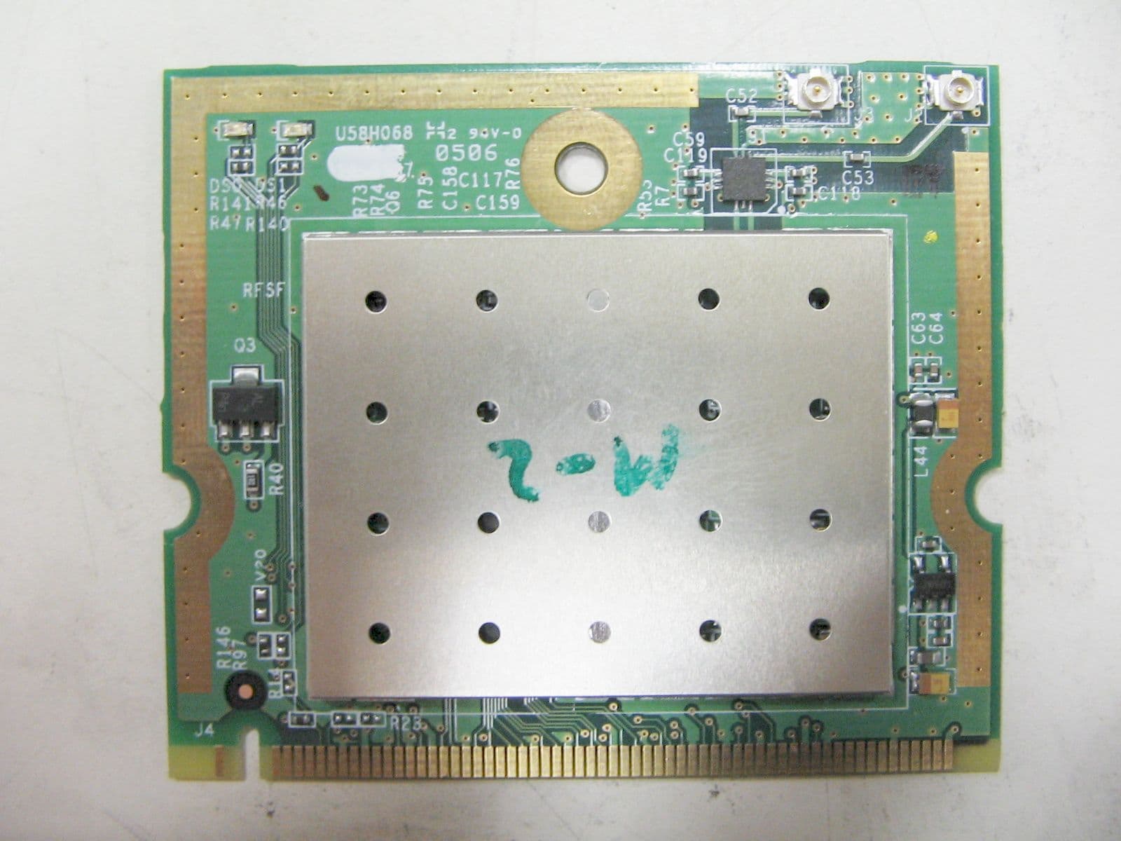
Click to zoom
Application Details
- Equipment Class
- TNB - Licensed Non-Broadcast Station Transmitter
- Date of Grant
- Jul 03, 2005
- Application Purpose
- Original Equipment
- Date of Application
- Jul 03, 2005
- Equipment Note
- 4.9 GHz WMIC Mini PCI Module
- Frequency Range
- 4952.50000000 - 4981.50000000
- Company
- Cisco Systems Inc
- Country
- United States
Documents & Files
Document Text
Text extracted from the exhibit documents filed with the FCC. Open a document above to read the original.
Users Manual
Corporate Headquarters Cisco Systems, Inc. 170 West Tasman Drive San Jose, CA 95134-1706 USA http://www.cisco.com Tel: 408 526-4000 800 553-NETS (6387) Fax: 408 526-4100 Cisco 3200 Series Wireless MIC Software Configuration Guide June 2005 Text Part Number: OL-7734-02 THE SPECIFICATIONS AND INFORMATION REGARDING THE PRODUCTS IN THIS MANUAL ARE SUBJECT TO CHANGE WITHOUT NOTICE. ALL STATEMENTS, INFORMATION, AND RECOMMENDATIONS IN THIS MANUAL ARE BELIEVED TO BE ACCURATE BUT ARE PRESENTED WITHOUT WARRANTY OF ANY KIND, EXPRESS OR IMPLIED. USERS MUST TAKE FULL RESPONSIBILITY FOR THEIR APPLICATION OF ANY PRODUCTS. THE SOFTWARE LICENSE AND LIMITED WARRANTY FOR THE ACCOMPANYING PRODUCT ARE SET FORTH IN THE INFORMATION PACKET THAT SHIPPED WITH THE PRODUCT AND ARE INCORPORATED HEREIN BY THIS REFERENCE. IF YOU ARE UNABLE TO LOCATE THE SOFTWARE LICENSE OR LIMITED WARRANTY, CONTACT YOUR CISCO REPRESENTATIVE FOR A COPY. The Cisco implementation of TCP header compression is an adaptation of a program developed by the University of California, Berkeley (UCB) as part of UCB’s public domain version of the UNIX operating system. All rights reserved. Copyright © 1981, Regents of the University of California. NOTWITHSTANDING ANY OTHER WARRANTY HEREIN, ALL DOCUMENT FILES AND SOFTWARE OF THESE SUPPLIERS ARE PROVIDED “AS IS” WITH ALL FAULTS. CISCO AND THE ABOVE-NAMED SUPPLIERS DISCLAIM ALL WARRANTIES, EXPRESSED OR IMPLIED, INCLUDING, WITHOUT LIMITATION, THOSE OF MERCHANTABILITY, FITNESS FOR A PARTICULAR PURPOSE AND NONINFRINGEMENT OR ARISING FROM A COURSE OF DEALING, USAGE, OR TRADE PRACTICE. IN NO EVENT SHALL CISCO OR ITS SUPPLIERS BE LIABLE FOR ANY INDIRECT, SPECIAL, CONSEQUENTIAL, OR INCIDENTAL DAMAGES, INCLUDING, WITHOUT LIMITATION, LOST PROFITS OR LOSS OR DAMAGE TO DATA ARISING OUT OF THE USE OR INABILITY TO USE THIS MANUAL, EVEN IF CISCO OR ITS SUPPLIERS HAVE BEEN ADVISED OF THE POSSIBILITY OF SUCH DAMAGES. Cisco 3200 Series Wireless MIC Software Configuration Guide Copyright © 2005 Cisco Systems, Inc. All rights reserved. CCIP, CCSP, the Cisco Arrow logo, the Cisco Powered Network mark, Cisco Unity, Follow Me Browsing, FormShare, and StackWise are trademarks of Cisco Systems, Inc.; Changing the Way We Work, Live, Play, and Learn, and iQuick Study are service marks of Cisco Systems, Inc.; and Aironet, ASIST, BPX, Catalyst, CCDA, CCDP, CCIE, CCNA, CCNP, Cisco, the Cisco Certified Internetwork Expert logo, Cisco IOS, the Cisco IOS logo, Cisco Press, Cisco Systems, Cisco Systems Capital, the Cisco Systems logo, Empowering the Internet Generation, Enterprise/Solver, EtherChannel, EtherSwitch, Fast Step, GigaStack, Internet Quotient, IOS, IP/TV, iQ Expertise, the iQ logo, iQ Net Readiness Scorecard, LightStream, MGX, MICA, the Networkers logo, Networking Academy, Network Registrar, Pa cke t, PIX, Post-Routing, Pre-Routing, RateMUX, Registrar, ScriptShare, SlideCast, SMARTnet, StrataView Plus, Stratm, SwitchProbe, TeleRouter, The Fastest Way to Increase Your Internet Quotient, TransPath, and VCO are registered trademarks of Cisco Systems, Inc. and/or its affiliates in the United States and certain other countries. All other trademarks mentioned in this document or Website are the property of their respective owners. The use of the word partner does not imply a partnership relationship between Cisco and any other company. (0401R) iii Cisco 3200 Series Wireless MIC Software Configuration Guide OL-7734-02 CONTENTS Prefacexv Audiencexv Purposexv Organizationxv Conventionsxvii Related Documentationxix Obtaining Documentationxx Cisco.comxx Ordering Documentationxx Documentation Feedbackxx Tools and Web Sitesxx Obtaining Additional Publications and Informationxxi Cisco 3200 Documentation CDxxii System Requirements for the CDxxii Printing Documents from the CDxxii Obtaining Technical Assistancexxiii Cisco TAC Websitexxiii Opening a TAC Casexxiii TAC Case Priority Definitionsxxiii Obtaining Additional Publications and Informationxxiv CHAPTER1Overview1-1 Understanding the Cisco Mobile Wireless Network1-2 Network Configuration Descriptions1-2 Access Point Mode1-2 Point-to-Point Bridging1-2 Point-to-Multipoint Bridging1-3 Redundant Bridging1-4 Workgroup Bridge Mode1-4 Features1-4 Management Options1-7 CHAPTER2Configuring the WMIC for the First Time9 Before You Start10 Contents iv Cisco 3200 Series Wireless MIC Software Configuration Guide OL-7734-02 Connecting to the WMIC10 Using the Console Port to Access the Exec10 Using a Telnet Session to Access the Exec11 Opening the CLI with Secure Shell11 Obtaining and Assigning an IP Address12 Assigning an IP Address By Using the Exec12 Assigning Basic Settings By Using the Web Browser13 Default Settings on the Express Setup Page16 Protecting Your Wireless LAN16 Configuring Basic Security Settings17 Understanding Express Security Settings18 Using VLANs18 Express Security Types18 Express Security Limitations19 Using the Express Security Page20 CLI Security Configuration Examples20 Example: No Security20 Example: Static WEP21 Example: EAP Authentication22 Example: WPA23 Using the IP Setup Utility24 Obtaining and Installing IPSU24 Using IPSU to Find the WMIC IP Address25 Using IPSU to Set the IP Address and SSID26 CHAPTER3Administering the WMIC2-1 Configuring a System Name and Prompt2-2 Configuring a System Name2-2 Managing DNS2-2 Default DNS Configuration2-3 Setting Up DNS2-3 Displaying the DNS Configuration2-4 Creating a Banner2-4 Default Banner Configuration2-4 Configuring a Message-of-the-Day Login Banner2-4 Configuring a Login Banner2-5 Managing the System Time and Date2-6 Understanding the System Clock 2-6 Understanding Network Time Protocol2-6 Contents v Cisco 3200 Series Wireless MIC Software Configuration Guide OL-7734-02 Configuring NTP2-9 Default NTP Configuration2-9 Configuring NTP Authentication2-9 Configuring NTP Associations2-11 Configuring NTP Broadcast Service2-12 Configuring NTP Access Restrictions2-14 Configuring the Source IP Address for NTP Packets2-16 Displaying t…
Text truncated - open the document above for the full version.
Cover Letter(s)
June 11, 2005 RE: Cisco Systems, Inc. FCC ID: LDKXSCLCR14 1) The Term “FCC ID:” and the ID Number “LDKXSCLCR14” are shown on 2 separate lines. Note that 2.925 Identification of equipment, states: (a) Each equipment covered in an application for equipment authorization shall bear a nameplate or label listing the following: (b) FCC Identifier consisting of the two elements in the exact order specified in §2.926. The FCC Identifier shall be preceded by the term FCC ID in capital letters on a single line, and shall be of a type size large enough to be legible without the aid of magnification. Response: Due to the size of the Mini PCI the FCC ID label had to be reduced to size and this did not allow the FCC ID to follow before the ID number. Let us know if this is still a problem. 2) Information in the operational description mentions a Version 1 and Version 2, which utilize different components and chipsets. Because of their design differences, this will require that each version have their own unique FCC ID. Please clarify which version is being covered by this application. Note that parts lists and schematics suggest this is for Version 2. Response: Version 1 was only produced as prototypes for debug and testing. 3) Documentation in the operational description appears to mentions that the device can contain 2 different amplifiers. Which one is evaluated for use in this application. Please explain. Response: Version 1 (proto only) was made with different components, specifically a two chip set. Version 2 has a single chip which replaces them. The only power amp used is LX5506 which was used in the units that were tested. 4) Please provide a cover letter to address the attached licensed module policy. Response: Module letter has been uploaded. 5) Please explain the reference to the 2.4 GHz band in the RF exposure exhibit. Response: Per Cisco configuration guide label “manual part 5”, a pre-approve Wi-Fi module will be installed with the 4.9 GHz Mini PCI module which both will be transmitting and operating at the same time. So for the RF exposure Co-location and worse case configuration was taken into consideration (Refer to MPE data). 6) Please provide a description of all circuitry and devices provided for determining and stabilizing frequency, for suppression of spurious radiation, for limiting modulation, and for limiting power. Response: Y1 = 40 MHz (XTAL) Frequency stability, The modulation limit and power is controlled by software in the Atheros chip U1 (AR5414) and scrip files, F2 DEA165850LT- 1197B2 low pass filter to suppress spurious emissions at antenna port. This information has been included in the report. 7) This device could be used in point-to-point or point-to-multipoint system. Is the Applicant aware of the potential site license limitations imposed by 90.1207(d)? Given the nature of this device and being approved as a module, it may be prudent to included additional information regarding this fact in the users manual. Response: Yes they will be made aware. Cisco has ways of informing their clients about part 90.1207(d) it could be put into documentation that is on the web rather easily. 8) Page 2 of the RF exposure for fixed installations mentions 20 cm. Given the estimated distances, this seems incorrect. Please review. Response: MPE sheets have been corrected and uploaded a revised sheet. 9) The tune up procedure provided is actually a 300 page users manual. Please kindly provide an appropriate tune-up procedure as specified by 2.1043(c)(9). Response: The radio has no tuning components. All tuning is control by the Atheros chip AR5414A and scrips. Letter explaining this has been uploaded. 10) The Channel frequencies specified in the operational description do not appear to match the channels specified in 90.1213. Please explain/correct as necessary. Response: This was due to the nature of the radio software (ART) limitation that did not allow the frequency to be program by .5 MHz increments. The software only allowed programming the Mini PCI card by 5 MHz increments. Cisco’s software will be operating per FCC frequency assignments. Refer to 4-7 to 4-9 of the Cisco 3200 Series Wireless MIC software configuration Guide label “manual part 5”. 11) Kindly show how this device will meet the chanelization requirements of 90.1213. Please provide a complete list of all channels and their associated bandwidths. Note that the 731 form only shows 5, 10, and 20 MHz bandwidths. Are 1 MHz bandwidths not being utilized? Response: Per the Theory of Operation page 7 of 24 it states the channelization capabilities of the radio being 5, 10, and 20 MHz. An also stated the data rates. 1.5Mbps for 5 MHz, 3Mbps for 10MHz, and 6Mbps for 20MHz. This radio does not have 1 MHz channelization capabilities. For the channel and their associated bandwidths please refer to 4-7 to 4-9 of the Cisco 3200 Series Wireless MIC software configuration Guide label “Manual part 5”. 12) Kindly explain compliance to 90.1215(a) for the antenna used. Response: Per the RF exposure calculations the antenna gain does not exceed 9dBi (Max is 7.5dBi) for mobile applications. Per statement for “fixed” locations used for point to point or point to multipoint the gain of the antenna must not exceed 26dBi (Max is 21dBi). This stated this shows that the antenna(s), for both mobile and fixed applications, do not exceed the max gain limits, before power and PSD reduction is required, as stated in section 90.1215(a). 13) 90.1205 prohibit aeronautical mobile operation. Some of the information in the antennas specifications appear to suggest designs for helicopters, etc. Please comment. Response: Although antenna is specified for use in helicopters, the true applications will be for cars only. 14) In addition to the RF Exposure evaluation, a statement confirming compliance with the RF Safety requirements for both fundamental and unwanted emissions must be submitted. Please see 90.1217. Response: Letter stating compliance with the R…
Text truncated - open the document above for the full version.
Cover Letter(s)
June 21, 2005 RE: Cisco Systems, Inc. FCC ID: LDKXSCLCR14 1) We have submitted the labeling example to the FCC for final comment. We will let you know the outcome of this correspondence. Response: Understood. 2) You state that you used a different power measurement technique. If RMS equivalent measurements are not possible please specify how your method is equivalent. A presentation of oscilloscope plots showing the EUT fundamental and the reference levels measured and used would be helpful to show RMS equivalence. Response: No other method was used other then the procedural methods stated in the UNII Procedure (DA-02-2138). This method is used if the transmitter cannot be set to 100% duty cycle, which was the case for the 4.9Ghz Mini PCI card. Method #3 Set span to encompass the entire emission bandwidth (EBW) of the signal. Set sweep trigger to “free run”. Set RBW = 1 MHz. Set VBW ε 1/T Use linear display mode. Use sample detector mode if bin width (i.e., span/number of points in spectrum) < 0.5 RBW. Otherwise use peak detector mode. Set max hold. Allow max hold to run for 60 seconds. Below is an explanation for the use of the Sample detector to simulate RMS detection. 3) The software (manual page 4-10) appears to show you can configure to non-supported channels. Please explain. The concern is that the device meets the channels specified in 90.1213 only. Response: The manual has been was revised to state the supported channels. If the non- supported channels are entered into the command line it will return an error stating that no such command exist. Regards, Juan Martinez Senior EMC Engineer JM/dmg
Cover Letter(s)
File: R59558 April 23, 2005 ATCB 6731 Whittier Ave Suite C110 McLean, Va. 22101 Gentlemen: The enclosed documents constitute a formal submittal and request for a Certification pursuant to Part 90 of FCC Rules (CFR 47) regarding to Public Mobile Service. Certification is being requested for Microwave Data Systems model U58H068. The U58H068 has been tested and found to comply with FCC Part 90 limits. Elliott Laboratories, as duly authorized agent prepared this submittal. A copy of the letter of our appointment as agent is enclosed. If there are any questions or if further information is needed, please contact Elliott Laboratories for assistance. Sincerely, Juan Martinez Senior EMC Engineer JM/dmg Enclosures: Agent Authorization Letter Confidentiality Letter Schematics External and Internal Photos Manual Theory of Operations FCC ID Label and Location Emissions Test Report with Exhibits
Cover Letter(s)
Below is a response that David Case (Cisco) received from the FCC (Tim Maguire) concerning the frequency use. Fred From the Wireless Bureau of the FCC, send this to the TCB, basically the FCC WB has no real issue though our coordination !!! From: Tim Maguire [mailto:[email protected]] Sent: Friday, July 01, 2005 10:17 AM To: David Case (davecase) Subject: RE: Fwd: Response to Inquiry to FCC (Tracking Number 514157) (Cisco) Dave, Bottom line on this issue is its better when combining channels not to use the center frequencies in the rules, but to move the center to a band edge. It will be easier to coordinate, and I believe this is what manufacturers are doing, generally. If you use the center freqs in the rules when combing channels, its is not as spectrally efficient. I wouldn't say its a rules violation, but it just makes better sense to use a different center to maximize the efficiency of the band, and like I said for easier coordination. I hope this answers your question, have a good vacation. I'm also going on vacation next week, starting in a couple of hours. I'll be checking my e-mail sporadically if something comes up. Enjoy, Tim David A. Case NCE, NCT Cisco Systems Inc Senior Regulatory Engineer Corporate Compliance EMC Standards and Operations Stonegate Corp Park 4125 Highlander Parkway Richfield OH 44286 T 330-523-2139 Subject: FW: Fwd: Response to Inquiry to FCC (Tracking Number 514157) (Cisco) From: "Fred Leffingwell \(fleffing\)" <[email protected]> To: "Documentation Group ...snip... [email protected]> Cc: "Juan Martinez" <jmartinez ...snip... [email protected]>
Cover Letter(s)
In response to RT 26874, the average power was inadvertently listed on the certificate based upon information on the bottom of page 38 of 59 (labeled 16 of 29 in the report). This has been corrected on the grant. Since RF exposure information in 2.1091 cites “In general, maximum average power levels must be used to determine compliance.”, this change would not be expected to affect RF exposure which was originally calculated based upon maximum average power as allowed per 2.1091. Please let us know if there are any further concerns. ATCB -----------RT 26874 --------- To: William Graff From: Tim Harrington [email protected] FCC Equipment Authorization Branch Re: FCC ID: LDKXSCLCR14 Applicant: Cisco Systems Inc Correspondence Reference Number: 26874 731 Confirmation Number: TC371093 Date of Original Email: 03/02/2006 Subject: audit TCB to address: EMC report but not form731 appears to show P>20 dBm max power - please explain and/or revise The items indicated above must be submitted before processing can continue on the above referenced application. Failure to provide the requested information within 30 days of the original e-mail date may result in application dismissal pursuant to Section 2.917(c). DO NOT Reply to this email by using the Reply button. In order for your response to be processed expeditiously, you must upload your response via the Internet at www.fcc.gov , E-Filing, OET TCB Electronic Filing, TCB Login. If the response is submitted through Add Attachments, a message which informs the processing staff that a new exhibit has been submitted must also be submitted via Submit Correspondence. Also, please note that partial responses increase processing time and should not be submitted. Any questions about the content of this correspondence should be directed to the e-mail address listed below the name of the sender.
ID Label/Location Info
FCC Label
ID Label/Location Info
UPDATE DESCRIPTION * 0.2 CRITICAL DIM. MARKDRAFT TOLERANCE FE D C 1 2 3 4 MATERIAL (SPEC.) Dim. 30~120 120~300 300~450 450~600 0.1 0.2 0.2 0.1 0.0 Tol. 0.2 0.3 0.4 0.1 0.0 6~30 0~6 0.30.5 FINISH Select 15.0 10.0 5.0 3.0 BAG 20.00 2.0 0.5 1.0 0.5 EPE 2.0 0.5 0.5 EPS 1.0 0.3 0.4 0.5 0.2 0.1 3.03.0 0.6 0.2 0.2 0.3 0.5 0.2 Label CTN 3.0 2.0 5.0 USR 0.8 5.0 UNIT PART NAME CUSTOMER MODEL mm SIZE A4 MODEL SHEET SCALE F E D VER. 0.0 D C R / E C N N O . MARK C First Release DATE B A APPROVED DESIGNED CUSTOMER PART NO. PART NO. 1 2 3 4 BA SIGNATURE N/S 1/1 2005/05/04 KAREN JASON * U58H068.00 Formal Release RESA Note: 1.Blue is dieline, does not print. 2.Dimension : 20 x 3 mm. 3.: 0.1 2005/06/22 KAREN FCC ID:LDKXSCLCR14 PTT LABEL U58H068.00 500.00054.005 FCC ID:LDKXSCLCR14
Operational Description
4.9 - 5.4 GHz Subscriber Antenna 4.9 - 5.4 GHz Subscriber Antenna MA-WA49-1X Mars 4.9 - 5.4 GHz Antenna provides a cost effective solution for large scale WLL, UNII and for public safety applications. Additional Features: • Minimum Gain of 21 dBi over the entire frequency range. • Light weight and durable construction. • DC grounded for lightning protection to meet local electrical building codes. Specifications : Electrical Frequency range 4.9 - 5.4 GHz GAIN, min. 21 dBi VSWR, max. 1.9:1 Polarization Linear, Vertical 3 dB Beam Width - Az./El., typ. 10.5 o Cross Polarization, min 24 dB Power Handling 10 Watts Input Impedance 50 Ohms Front to Back Ratio, min. 35 dB Mechanical and Environmental Dimensions (LxWxD) 305x305x15 mm (DIAMOND Shape) Base Plate Aluminum, Coated Radome Plastic, UV protected Temperature -40 o C up to +75 o C Input/ RF Interface N-Type (others available) Mounting Hardware Pole Mount & Brackets –Standard Optional- MNT-2 Az/ El adjustable mount Specifications subject to change without notice SECTOR PSB 60 DEG Public Safety Band Sector Antenna, 60 o MA-WC49-5X Mars 4.95 GHz Sector Antenna provides an effective solution for Sectorized Public Safety Band Applications. Features: • High gain • Small Size • Pole mount with mechanical tilting Specifications: Electrical Frequency range 4.94 - 4.99 GHz Gain, typ. 17 dBi VSWR, max. 1.7 : 1 3dB Beam-Width – Azimuth, typ. 60 o 3dB Beam-Width – Elevation, typ. 6 o Polarization Linear Vertical Cross-polarization Level, max. -20 dB Front to back ratio -25 dB Power Handling 50 Watts Input Impedance 50 Ohms Mechanical and Environmental Dimensions (LxWxD) 500x80x80 mm Radome Plastic, UV protected Connector N-Type, F Mount (Optional) Tilt Mount (0-12 o ) for Pole 2-4” Lightning Protection DC Grounded Temperature -40 o C to +70 o C Specifications subject to change without notice SECTOR PSB 90 DEG Public Safety Band Sector Antenna, 90 o MA-WD49-6X Mars 4.95 GHz Sector Antenna provides an effective solution for Sectorized Public Safety Band Applications. Features: • High gain • Small Size • Pole mount with mechanical tilting Specifications: Electrical Frequency range 4.94 - 4.99 GHz Gain, typ. 16 dBi VSWR, max. 1.7 : 1 3dB Beam-Width – Azimuth, typ. 90 o 3dB Beam-Width – Elevation, typ. 6 o Polarization Linear Vertical Cross-polarization Level, max. -20 dB Front to back ratio -25 dB Power Handling 50 Watts Input Impedance 50 Ohms Mechanical and Environmental Dimensions (LxWxD) 500x80x80 mm Radome Plastic, UV protected Connector N-Type, F Mount (Optional) Tilt Mount (0-12 o ) for Pole 2-4” Lightning Protection DC Grounded Temperature -40 o C to +70 o C Specifications subject to change without notice SECTOR PSB 120 DEG Public Safety Band Sector Antenna, 120 o MA-WE49-7X Mars 4.95 GHz Sector Antenna provides an effective solution for Sectorized Public Safety Band Applications. Features: • High gain • Small Size • Pole mount with mechanical tilting Specifications: Electrical Frequency range 4.94 - 4.99 GHz Gain, typ. 15 dBi VSWR, max. 1.7 : 1 3dB Beam-Width – Azimuth, typ. 120 o 3dB Beam-Width – Elevation, typ. 6 o Polarization Linear Vertical Cross-polarization Level, max. -20 dB Front to back ratio -25 dB Power Handling 50 Watts Input Impedance 50 Ohms Mechanical and Environmental Dimensions (LxWxD) 500x80x80 mm Radome Plastic, UV protected Connector N-Type, F Mount (Optional) Tilt Mount (0-12 o ) for Pole 2-4” Lightning Protection DC Grounded Temperature -40 o C to +70 o C Specifications subject to change without notice Blade Antenna for mobile Public Safety Applications MA-WO49-BX This antenna is a rugged, aerodynamic antenna for the 4.94 to 4.99 GHz (Public Safety Band) to be used in mobile applications such as trains, helicopters, buses or cars. The antenna comes in two versions: • Fixed Mount (Roof top) • Magnetic Mount (Side Pigtail) Specifications: Electrical Frequency Band 4.94 – 4.99 GHz Gain, typical 5 dBi Polarization Vertical 3 dB Beam Width (H-Plane), typ. Omni-Directional 3 dB Beam Width (E-Plane), typ. 60° VSWR, (max.) 1.5 : 1 Power Handling (max) 50 W Impedance 50 Ohms Mechanical and Environmental Dimensions- Height Base Diameter <10” <5” Mount Magnetic Mount – (Specify X=M) Fixed Roof-top Mount -(Specify X=F) Connector For Magnet Mount :Coaxial Pigtail (RG316) of 10” ended in a MCX female connector For Fixed Mount : N-type female RadomePlastic, UV protected Weight<1 Kg Vibration Sinusoidal , 5 to 500 Hz up to 5 G 2 /Hz Temperature (operating/storage) -40°C to +70°C SPECIFICATIONS SUBJECT TO CHANGE OMNI PS MA-WO49-7X Omni-Directional Public Safety Band Antenna MA-WO49-7X Mars 4.95 GHz Omni Directional Antenna provides an effective solution for fixed, (pole mount) Public Safety Applications. Specifications: Electrical Frequency range 4.94 - 4.99 GHz Gain 7.5 dBi VSWR, max. 1.7 : 1 Azimuth Beam-Width Omni- Directional Elevation Beam-Width (typ.) 12 o Polarization Linear Vertical Power Handling 50 Watt Mechanical and Environmental Dimensions (H x Dia.) 420 x 32mm (16.5" x 1.3") Weight 225 g Connector N-Type, Female Mount 2.5" Pole mount (end) attachment Specifications subject to change without notice
Parts List/Tune Up Info
June 10, 2005 American TCB 6731 Whittier Ave. Suite C110 McLean, VA 22101 Attn: Director of Certification This letter is to notify that the radio model: U58H068, FCC ID: LDKXSCLCR14 has no field hardware adjustments points. All configuration changes possible are made via software, and are described in the Cisco Configuration manual for this equipment. Therefore, no tune-up procedure is submitted for the equipment. Regards, Juan Martinez Sr. EMC Engineer
RF Exposure Info
June 10, 2005 American TCB 6731 Whittier Ave. Suite C110 McLean, VA 22101 Attn: Director of Certification In accordance with FCC 90.1217 RF hazard and OET 65 Supplement C (Edition 01-01) we hereby declare that U58H068 Mini PCI module has been evaluated and found to comply with the RF exposure limits for humans, as specified in FCC part 1 & 2 sections 1.1037 and 2.1091. This declaration is based on test data, which has been submitted with our application for certification. Regards, Juan Martinez Sr. EMC Engineer
RF Exposure Info
Formula is: 1 1406.52 10.6 Peak Average dBm W W dBm 2400 - 2483.5 CCK - 20.0 7.5 27.5 0.562 11 1 0.562 27.50 2400 - 2483.5 CCK - 20.0 7.5 27.5 0.562 11 1 0.562 27.50 4940 - 4990 OFDM - 17.0 7.5 24.5 0.282 10 1 0.282 24.50 3 1.407 31.48 Formula is: 1 1687.02 11.6 Peak Average dBm W W dBm 2400 - 2483.5 CCK - 20.0 7.5 27.5 0.562 11 1 0.562 27.50 2400 - 2483.5 CCK - 20.0 7.5 27.5 0.562 11 1 0.562 27.50 2400 - 2483.5 CCK - 20.0 7.5 27.5 0.562 11 1 0.562 27.50 3 1.687 32.27 Formula is: 1 1126.02 9.5 Peak Average dBm W W dBm 2400 - 2483.5 CCK - 20.0 7.5 27.5 0.562 11 1 0.562 27.50 4940 - 4990 OFDM - 17.0 7.5 24.5 0.282 10 1 0.282 24.50 4940 - 4990 OFDM - 17.0 7.5 24.5 0.282 10 1 0.282 24.50 3 1.126 30.52 Totals: MPE exposure is based on two 4.9GHz transmitter and one 2.4GHz radio. Device can be programmed to transmitt simultaneously. EIRP Channels Available Channels Used Total EIRP Band Mode Output Power Antenna gain (Max) Frequency (MHz) MPE Limit (mW /cm 2 ) Eirp (mW) Pd = Pt / (4*pi*d 2 ) Distance where Pd = Limit (cm) 2400 - 4990 0.22 Pd at 20cm (mW /cm 2 ) MPE exposure is based on three 2.4GHz transmitter. Device can be programmed to transmitt simultaneously. MPE Calculations (Mobile) Pd = Pt / (4*pi*d 2 ) Frequency (MHz) MPE Limit (mW /cm 2 ) Eirp (mW) Pd at 20cm (mW /cm 2 ) Distance where Pd = Limit (cm) Pd = Pt / (4*pi*d 2 ) Distance where Pd = Limit (cm) 0.28 Channels Used Totals: 2400 - 4990 MPE Limit (mW /cm 2 ) EIRP Eirp (mW) Pd at 20cm (mW /cm 2 ) Totals: MPE exposure is based on two 2.4GHz pre-approved modules with one 4.9GHz transmitter. Device can be programmed to transmitt simultaneously. Total EIRP 2400 - 4990 0.34 Channels Available Channels Used Band Mode Output Power Antenna gain (Max) The device is not a portable device (i.e. intended to be worn on the body or be hand-held), so it is classified as being either a mobile device or a fixed mounted device. The userís manual specifies a minimum separation distance of at least 20cm, consistent with this classif ication. FCC part 1.1310, Table 1 limits the power density for uncontrolled exposure. The power density, Pd (mW/cm2 ) calculated from t he maximum EIRP, Pt (mW) and the distance, d (m), between the transmitting antenna and the closest person, can be calculated using: Band Mode Output Power Antenna gain (Max) EIRP Channels Available Total EIRP Frequency (MHz) Formula is: 1 11333.35 30.0 Peak Average dBm W W dBm 2400 - 2483.5 CCK - 13.0 21.0 34.0 2.512 11 1 2.512 34.00 2400 - 2483.5 CCK - 13.0 21.0 34.0 2.512 11 1 2.512 34.00 4940 - 4990 OFDM - 17.0 21.0 38.0 6.310 10 1 6.310 38.00 3 11.333 40.54 Formula is: 1 7535.66 24.5 Peak Average dBm W W dBm 2400 - 2483.5 CCK - 13.0 21.0 34.0 2.512 11 1 2.512 34.00 2400 - 2483.5 CCK - 13.0 21.0 34.0 2.512 11 1 2.512 34.00 2400 - 2483.5 CCK - 13.0 21.0 34.0 2.512 11 1 2.512 34.00 3 7.536 38.77 Formula is: 1 15131.03 34.7 Peak Average dBm W W dBm 2400 - 2483.5 CCK - 13.0 21.0 34.0 2.512 11 1 2.512 34.00 4940 - 4990 OFDM - 17.0 21.0 38.0 6.310 10 1 6.310 38.00 4940 - 4990 OFDM - 17.0 21.0 38.0 6.310 10 1 6.310 38.00 3 15.131 41.80 Pd = Pt / (4*pi*d 2 ) Total EIRP Totals: MPE exposure is based on three 2.4GHz transmitter. Device can be programmed to transmitt simultaneously. Antenna gain (Max) EIRP Channels Available Channels Used Band Mode Output Power Pd = Pt / (4*pi*d 2 ) Frequency (MHz) MPE Limit (mW/cm 2 ) Eirp (mW) MPE Limit (mW/cm 2 ) Eirp (mW) Pd at 20cm (mW/cm 2 ) 2400 - 4990 2.25 MPE Calculations (Fixed Location) The device is not a portable device (i.e. intended to be worn on the body or be hand-held), so it is classified as a fixed moun ted device. The userís manual specifies a minimum separation distance of at least 35cm, consistent with this classification. FCC part 1.1310, Table 1 limits the power density for uncontrolled exposure. The power density, Pd (mW/cm2 ) calculated from t he maximum EIRP, Pt (mW) and the distance, d (m), between the transmitting an tenna and the closest person, can be calculated using: Pd = Pt / (4*pi*d 2 ) Distance where Pd = Limit (cm) 2400 - 4990 3.01 Distance where Pd = Limit (cm) Channels Available Frequency (MHz) MPE Limit (mW/cm 2 ) Eirp (mW) Pd at 20cm (mW/cm 2 ) Frequency (MHz) Channels Used Total EIRP Totals: MPE exposure is based on two 2.4GHz pre-approved modules with one 4.9GHz transmitter. Device can be programmed to transmitt si multaneously. Band Mode Output Power Antenna gain (Max) EIRP Pd at 20cm (mW/cm 2 ) Distance where Pd = Limit (cm) 2400 - 4990 1.50 Band Mode Output Power Total EIRP Totals: MPE exposure is based on two 4.9GHz transmitter and one 2.4GHz radio. Device can be programmed to transmitt simultaneously. Antenna gain (Max) EIRP Channels Available Channels Used
Test Report
File: R59558 Page 1 of 19 Electromagnetic Emissions Test Report In Accordance With FCC Part 90 on the Cisco Systems, Inc. Transmitter Model: U58H068 FCC ID NUMBER: LDKXSCLCR14 GRANTEE:Cisco Systems, Inc. 170 West Tasman Drive San Jose, CA 95134 TEST SITE:Elliott Laboratories, Inc. 684 W. Maude Ave Sunnyvale, CA 94086 REPORT DATE:April 23, 2005 FINAL TEST DA…
Text truncated - open the document above for the full version.
Contact Information
Applicant
Samuel Kim(Manager, Engineering)
Technical Contact
Elliott Laboratories Inc.Juan Martinez
[email protected]408-245-7800
684 West Maude Ave. · Sunnyvale, California · United States
Non-Technical Contact
Elliott Laboratories Inc.Juan Martinez
[email protected]408-245-7800
Test Firm
Elliott Laboratories LLCDavid Bare
Technical Specifications
| # | Rule Parts | Frequency Range | Power Output | Emission | Tolerance |
|---|---|---|---|---|---|
| 2 | 9 | 4.95 GHz - 4.98 GHz | 120.00 mW | 10M0X1D | 100 Hz |
Other Applications from Cisco Systems Inc

LDKJ98213058
May 25, 2026Wireless Phone
Equipment Class
DSS - Part 15 Spread Spectrum TransmitterLDKIW9165E
Aug 20, 2024Wi-Fi 6E Outdoor Access Point
Equipment Class
6SD - 15E 6 GHz Standard Power Access PointLDKIW9165DH
Aug 05, 2024Wi-Fi 6E Outdoor Access Point
Equipment Class
6SD - 15E 6 GHz Standard Power Access PointLDKUSBC2857
Jul 22, 2024Cisco Headset USB-C Adapter
Equipment Class
DSS - Part 15 Spread Spectrum TransmitterLDKESPRD2922
May 09, 2024UC Phone
Equipment Class
NII - Unlicensed National Information Infrastructure TX