LDKXSCLCR154.9 GHz WMIC Mini PCI Module
Cisco Systems Inc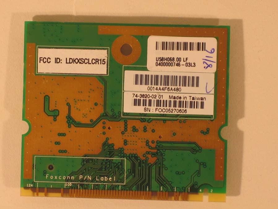
Click to zoom
Application Details
- Equipment Class
- TNB - Licensed Non-Broadcast Station Transmitter
- Date of Grant
- Oct 31, 2005
- Application Purpose
- Original Equipment
- Date of Application
- Oct 31, 2005
- Equipment Note
- 4.9 GHz WMIC Mini PCI Module
- Frequency Range
- 4950.00000000 - 4980.00000000
- Company
- Cisco Systems Inc
- Country
- United States
Documents & Files
Document Text
Text extracted from the exhibit documents filed with the FCC. Open a document above to read the original.
Users Manual
Corporate Headquarters: Copyright © 2005 Cisco Systems, Inc. All rights reserved. Cisco Systems, Inc., 170 West Tasman Drive, San Jose, CA 95134-1706 USA Regulatory Compliance and Safety Information for the Cisco 3200 Mobile Access Router Read this document before installing or servicing the Cisco 3200 Mobile Access Router. NoteOnly trained and qualified service personnel (as defined in IEC 60950 and AS/NZS 3260) should install, replace, or service the Cisco 3200 Mobile Access Router. Install the system in accordance with the U.S. National Electric Code if you are in the United States. CautionWhen equipped with the 4.9 GHz Wireless Mobile Interface Card (WMIC), the Cisco 3200 Mobile Access Router is only allowed to operate in the USA. It must operate as a licensed radio as a licensed public safety agency. WarningIMPORTANT SAFETY INSTRUCTIONS This warning symbol means danger. You are in a situation that could cause bodily injury. Before you work on any equipment, be aware of the hazards involved with electrical circuitry and be familiar with standard practices for preventing accidents. Use the statement number provided at the end of each warning to locate its translation in the translated safety warnings that accompanied this device. This document includes the following sections: •Translated Safety Warnings, page 2 •European Directives, page 42 •Regulatory Standards Compliance, page 43 •Regulatory Standards Compliance for the 4.9 GHz Wireless Mobile Interface Card, page 47 •EMC Class A Notices and Warnings, page 47 •EMC Class B Notices and Warnings, page 49 •Radio Frequency Exposure, page 50 •Environmental Impact, page 51 2 Regulatory Compliance and Safety Information for the Cisco 3200 Mobile Access Router 78-16930-02 Translated Safety Warnings •Related Documentation, page 51 •Obtaining Documentation, page 51 •Documentation Feedback, page 52 •Cisco Product Security Overview, page 53 •Obtaining Technical Assistance, page 54 •Obtaining Additional Publications and Information, page 55 Translated Safety Warnings This section contains the following translated safety warnings: •Statement 202—Installation and Replacement Warning •Statement 213—Unit Grounding Protection Warning •Statement 242—Equipment Grounding Warning •Statement 202—Installation and Replacement Warning •Statement 1003—DC Power Disconnection •Statement 1004—Installation Instructions •Statement 1006—Chassis Warning for Rack-Mounting and Servicing •Statement 1008—Class 1 Laser Product •Statement 1015—Battery Handling •Statement 1017—Restricted Area •Statement 1023—No. 26 AWG •Statement 1024—Ground Conductor •Statement 1029—Blank Faceplates and Cover Panels •Statement 1030—Equipment Installation •Statement 1031—EU Public Network Port •Statement 1032—Lifting the Chassis •Statement 1033—SELV-IEC 60950 DC Power Supply •Statement 1034—Backplane Voltage •Statement 1040—Product Disposal •Statement 1043—Installation Hazard •Statement 1046—Installing or Replacing the Unit •Statement 1051—Laser Radiation •Statement 1052—Installing and Grounding the Antenna •Statement 1064—Grounded Equipment 3 Regulatory Compliance and Safety Information for the Cisco 3200 Mobile Access Router 78-16930-02 Translated Safety Warnings Statement 202—Installation and Replacement Warning Statement 213—Unit Grounding Protection Warning WarningWhen installing or replacing the unit, the ground connection must always be made first and disconnected last. Statement 202 Waarschuwing Bij installatie of vervanging van het toestel moet de aardverbinding altijd het eerste worden gemaakt en het laatste worden losgemaakt. Varoitus Laitetta asennettaessa tai korvattaessa on maahan yhdistäminen aina tehtävä ensiksi ja maadoituksen irti kytkeminen viimeiseksi. Attention Lors de l’installation ou du remplacement de l’appareil, la mise à la terre doit toujours être connectée en premier et déconnectée en dernier. Warnung Der Erdanschluß muß bei der Installation oder beim Austauschen der Einheit immer zuerst hergestellt und zuletzt abgetrennt werden. Avvertenza In fase di installazione o sostituzione dell'unità, eseguire sempre per primo il collegamento a massa e disconnetterlo per ultimo. Advarsel Når enheten installeres eller byttes, må jordledningen alltid tilkobles først og frakobles sist. Aviso Ao instalar ou substituir a unidade, a ligação à terra deverá ser sempre a primeira a ser ligada, e a última a ser desligada. ¡Advertencia! Al instalar o sustituir el equipo, conecte siempre la toma de tierra al principio y desconéctela al final. Varning! Vid installation eller utbyte av enheten måste jordledningen alltid anslutas först och kopplas bort sist. WarningNever defeat the ground conductor or operate the equipment in the absence of a suitably installed ground conductor. Contact the appropriate electrical inspection authority or an electrician if you are uncertain that suitable grounding is available. Statement 213 Waarschuwing De aardingsleiding mag nooit buiten werking gesteld worden en de apparatuur mag nooit bediend worden zonder dat er een op de juiste wijze geïnstalleerde aardingsleiding aanwezig is. Neem contact op met de bevoegde instantie voor elektrische inspecties of met een elektricien als u niet zeker weet of voor passende aarding gezorgd is. 4 Regulatory Compliance and Safety Information for the Cisco 3200 Mobile Access Router 78-16930-02 Translated Safety Warnings Statement 242—Equipment Grounding Warning Varoitus Älä koskaan ohita maajohdinta tai käytä laitteita ilman oikein asennettua maajohdinta. Ota yhteyttä asianmukaiseen sähkötarkastusviranomaiseen tai sähköasentajaan, jos olet epävarma maadoituksen sopivuudesta. Attention Ne jamais rendre inopérant le conducteur de masse ni utiliser l’équipement sans un conducteur de masse adéquatement installé. En cas de doute sur la mise à la masse appropriée disponible, s’adresser à l’organisme responsable de la sécurité électrique ou à un électricien. Warnung Umgehen Sie auf keinen Fall den Erdungsleiter und nehmen Sie …
Text truncated - open the document above for the full version.
Users Manual
24 Regulatory Compliance and Safety Information for the Cisco 3200 Mobile Access Router 78-16930-02 Translated Safety Warnings 25 Regulatory Compliance and Safety Information for the Cisco 3200 Mobile Access Router 78-16930-02 Translated Safety Warnings Statement 1030—Equipment Installation WarningOnly trained and qualified personnel should be allowed to install, replace, or service this equipment. Statement 1030 Waarschuwing Deze apparatuur mag alleen worden geïnstalleerd, vervangen of hersteld door bevoegd geschoold personeel. Varoitus Tämän laitteen saa asentaa, vaihtaa tai huoltaa ainoastaan koulutettu ja laitteen tunteva henkilökunta. Attention Il est vivement recommandé de confier l'installation, le remplacement et la maintenance de ces équipements à des personnels qualifiés et expérimentés. Warnung Das Installieren, Ersetzen oder Bedienen dieser Ausrüstung sollte nur geschultem, qualifiziertem Personal gestattet werden. Avvertenza Questo apparato può essere installato, sostituito o mantenuto unicamente da un personale competente. Advarsel Bare opplært og kvalifisert personell skal foreta installasjoner, utskiftninger eller service på dette utstyret. Aviso Apenas pessoal treinado e qualificado deve ser autorizado a instalar, substituir ou fazer a revisão deste equipamento. ¡Advertencia! Solamente el personal calificado debe instalar, reemplazar o utilizar este equipo. Varning! Endast utbildad och kvalificerad personal bör få tillåtelse att installera, byta ut eller reparera denna utrustning. Aviso Somente uma equipe treinada e qualificada tem permissão para instalar, substituir ou dar manutenção a este equipamento. 26 Regulatory Compliance and Safety Information for the Cisco 3200 Mobile Access Router 78-16930-02 Translated Safety Warnings Statement 1031—EU Public Network Port Advarsel Kun uddannede personer må installere, udskifte komponenter i eller servicere dette udstyr. WarningIf the symbol of suitability with an overlaid cross appears above a port, you must not connect the port to a public network that follows the European Union standards. Connecting the port to this type of public network can cause severe personal injury or can damage the unit. Statement 1031 Waarschuwing Als er een geschiktheidssymbool met een overgetrokken kruis boven een poort aanwezig is, mag u deze poort niet op een openbaar netwerk aansluiten dat aan de normen van de Europese Unie voldoet. Als u de poort op een dergelijk openbaar netwerk aansluit, kan dit ernstig lichamelijk letsel veroorzaken of schade aan de eenheid. Varoitus Jos portin yläpuolelle ilmestyy soveltuvuussymboli, jonka päällä on rasti, porttia ei saa liittää Euroopan unionin standardien mukaiseen julkiseen verkkoon. Jos portti liitetään tällaiseen julkiseen verkkoon, seurauksena voi olla henkilövahinko tai laitteen vaurioituminen. 27 Regulatory Compliance and Safety Information for the Cisco 3200 Mobile Access Router 78-16930-02 Translated Safety Warnings Attention Si le symbole de capacité barré d'une croix apparaît au-dessus d'un port, il est vivement recommandé de ne pas connecter ce port à un réseau public aux normes de l'Union Européenne. Connecter ce port à ce type de réseau public peut causer de graves accidents ou endommager l'unité. Warnung Wenn oberhalb des Ports das Eignungssymbol mit einem Kreuz darüber erscheint, dürfen Sie den Port nicht an ein öffentliches Netz anschließen, das den Standards der Europäischen Gemeinschaft folgt. Das Anschließen des Port an ein solches Netz kann zu schweren Verletzungen führen oder die Einheit beschädigen. Avvertenza Se sopra una porta è riportato il simbolo di idoneità sbarrato, significa che la porta non può essere collegata a una rete pubblica a norma UE. Collegando la porta a tale rete pubblica si possono correre seri rischi e provocare danni all'unità. Advarsel Hvis symbolet for anvendelse med et kryss over vises over en utgang, skal utgangen ikke tilkobles et offentlig nettverk som følger EU-standardene. Hvis utgangen kobles til denne typen offentlig nettverk, kan det medføre alvorlig personskade eller skade på enheten. Aviso Se o símbolo de adequação com uma cruz sobreposta aparecer acima de uma porta, não conecte a porta a uma rede pública que obedece aos padrões da União Européia. A conexão da porta a este tipo de rede pública pode causar danos físicos ao operador ou danificar a unidade. ¡Advertencia! Si aparece el símbolo de idoneidad con una cruz sobrepuesta encima de un puerto, no debe conectarlo a una red pública que siga los estándares de la Unión Europea. Si conecta el puerto a este tipo de red puede lesionarse o dañar la unidad. Varning! Om lämplighetssymbolen med ett överlagt kors visas ovanför en port, får porten inte anslutas till ett offentligt nätverk av EU-standard. Om porten ansluts till denna typ av offentligt nätverk kan det orsaka allvarlig personskada eller skada enheten. 28 Regulatory Compliance and Safety Information for the Cisco 3200 Mobile Access Router 78-16930-02 Translated Safety Warnings Statement 1032—Lifting the Chassis WarningTo prevent personal injury or damage to the chassis, never attempt to lift or tilt the chassis using the handles on modules (such as power supplies, fans, or cards); these types of handles are not designed to support the weight of the unit. Statement 1032 Waarschuwing Om persoonlijk letsel of schade aan het chassis te voorkomen, dient u het chassis nooit aan de handvatten op de modules (zoals stroomvoorzieningen, ventilators of kaarten) op te tillen of te kantelen; deze handvatten zijn niet ontworpen om het gewicht van de eenheid te dragen. Varoitus Henkilövaurioiden ja asennuspohjan vahingoittumisen estämiseksi ei asennuspohjaa saa nostaa tai kallistaa moduulien kahvoista (esim. virtalähteiden, tuulettimien tai korttien kahvoista). Nämä kahvat eivät kestä koko laitteen painoa. Attention Pour éviter tout risque d'accident corporel et/ou de dommage matériel, n'essayez jamais de soulever ou de faire pivoter le châssis par les poigné…
Text truncated - open the document above for the full version.
Users Manual
Final Draft - Cisco Confidential Corporate Headquarters Cisco Systems, Inc. 170 West Tasman Drive San Jose, CA 95134-1706 USA http://www.cisco.com Tel: 408 526-4000 800 553-NETS (6387) Fax: 408 526-4100 Cisco 3200 Series Mobile Access Router Hardware Reference July 14, 2005 Customer Order Number: 85-4201-06 Text Part Number: OL-5816-04 Final Draft - Cisco Confidential THE SPECIFICATIONS AND INFORMATION REGARDING THE PRODUCTS IN THIS MANUAL ARE SUBJECT TO CHANGE WITHOUT NOTICE. ALL STATEMENTS, INFORMATION, AND RECOMMENDATIONS IN THIS MANUAL ARE BELIEVED TO BE ACCURATE BUT ARE PRESENTED WITHOUT WARRANTY OF ANY KIND, EXPRESS OR IMPLIED. USERS MUST TAKE FULL RESPONSIBILITY FOR THEIR APPLICATION OF ANY PRODUCTS. THE SOFTWARE LICENSE AND LIMITED WARRANTY FOR THE ACCOMPANYING PRODUCT ARE SET FORTH IN THE INFORMATION PACKET THAT SHIPPED WITH THE PRODUCT AND ARE INCORPORATED HEREIN BY THIS REFERENCE. IF YOU ARE UNABLE TO LOCATE THE SOFTWARE LICENSE OR LIMITED WARRANTY, CONTACT YOUR CISCO REPRESENTATIVE FOR A COPY. The Cisco implementation of TCP header compression is an adaptation of a program developed by the University of California, Berkeley (UCB) as part of UCB’s public domain version of the UNIX operating system. All rights reserved. Copyright © 1981, Regents of the University of California. NOTWITHSTANDING ANY OTHER WARRANTY HEREIN, ALL DOCUMENT FILES AND SOFTWARE OF THESE SUPPLIERS ARE PROVIDED “AS IS” WITH ALL FAULTS. CISCO AND THE ABOVE-NAMED SUPPLIERS DISCLAIM ALL WARRANTIES, EXPRESSED OR IMPLIED, INCLUDING, WITHOUT LIMITATION, THOSE OF MERCHANTABILITY, FITNESS FOR A PARTICULAR PURPOSE AND NONINFRINGEMENT OR ARISING FROM A COURSE OF DEALING, USAGE, OR TRADE PRACTICE. IN NO EVENT SHALL CISCO OR ITS SUPPLIERS BE LIABLE FOR ANY INDIRECT, SPECIAL, CONSEQUENTIAL, OR INCIDENTAL DAMAGES, INCLUDING, WITHOUT LIMITATION, LOST PROFITS OR LOSS OR DAMAGE TO DATA ARISING OUT OF THE USE OR INABILITY TO USE THIS MANUAL, EVEN IF CISCO OR ITS SUPPLIERS HAVE BEEN ADVISED OF THE POSSIBILITY OF SUCH DAMAGES. Cisco 3200 Series Mobile Access Router Hardware Reference Copyright © 2005, Cisco Systems, Inc. All rights reserved. CCIP, CCSP, the Cisco Arrow logo, the Cisco Powered Network mark, Cisco Unity, Follow Me Browsing, FormShare, and StackWise are trademarks of Cisco Systems, Inc.; Changing the Way We Work, Live, Play, and Learn, and iQuick Study are service marks of Cisco Systems, Inc.; and Aironet, ASIST, BPX, Catalyst, CCDA, CCDP, CCIE, CCNA, CCNP, Cisco, the Cisco Certified Internetwork Expert logo, Cisco IOS, the Cisco IOS logo, Cisco Press, Cisco Systems, Cisco Systems Capital, the Cisco Systems logo, Empowering the Internet Generation, Enterprise/Solver, EtherChannel, EtherSwitch, Fast Step, GigaStack, Internet Quotient, IOS, IP/TV, iQ Expertise, the iQ logo, iQ Net Readiness Scorecard, LightStream, MGX, MICA, the Networkers logo, Networking Academy, Network Registrar, Pa cke t, PIX, Post-Routing, Pre-Routing, RateMUX, Registrar, ScriptShare, SlideCast, SMARTnet, StrataView Plus, Stratm, SwitchProbe, TeleRouter, The Fastest Way to Increase Your Internet Quotient, TransPath, and VCO are registered trademarks of Cisco Systems, Inc. and/or its affiliates in the United States and certain other countries. All other trademarks mentioned in this document or Website are the property of their respective owners. The use of the word partner does not imply a partnership relationship between Cisco and any other company. (0401R) iii Cisco 3200 Series Mobile Access Router Hardware Reference OL-5816-04 CONTENTS Introduction to the Cisco 3200 Series Mobile Access Router Cardsi Audience and Scopeii Related Documentationii Obtaining Documentationiv Cisco.comiv Ordering Documentationiv Documentation Feedbackv Tools and Web Sitesv Obtaining Additional Publications and Informationvi Cisco 3200 Documentation CDvii System Requirements for the CDvii Printing Documents from the CDviii Conventionsviii Obtaining Technical Assistancexii Cisco Technical Support Websitexii Submitting a Service Requestxiii Definitions of Service Request Severityxiii CHAPTER 1Mobile Access Router Card (MARC)1-1 MARC Component Systems1-2 MARC Router Signals1-2 10/100 Fast Ethernet Signals on the MARC1-3 Console, Auxiliary, LED Signals, and Power1-4 MARC Power Requirements1-6 CHAPTER 2Fast Ethernet Switch Mobile Interface Card (FESMIC)2-1 Auto-Negotiation and Auto-MDI/MDIX2-2 MAC Address Allocation2-2 FESMIC Component Systems2-3 Signals for the FESMIC2-4 10/100 Fast Ethernet Signals on the FESMIC2-4 FESMIC LED Signals2-5 FESMIC Rotary Switch Positions2-7 Contents iv Cisco 3200 Series Mobile Access Router Hardware Reference OL-5816-04 CHAPTER 3Serial Mobile Interface Card (SMIC)3-1 SMIC Component Systems3-2 Signals for the SMIC3-3 Serial Cable Length3-3 SMIC LED Signals3-4 4-Port SMIC Rotary Switch Positions3-4 CHAPTER 4Wireless Mobile Interface Card (WMIC)4-1 WMIC Component Systems4-1 Signals for the WMIC4-2 10/100 Fast Ethernet Signals on the WMIC4-3 WMIC Multifunction Header Signals4-4 LED Behavior4-5 Antenna Connector4-6 Key Features4-6 2.4-GHz (802.11b/g) Features4-6 4.9-GHz (US Only, Public Safety) Features4-7 Throughput4-8 Modulation4-8 Receive Sensitivity4-8 2.4-GHz (802.11b/g) WMIC and the 4.9-GHz (US Only, Public Safety) Features4-9 MAC Address Allocation4-10 Power Requirements4-10 Related Documentation4-10 i Cisco 3200 Series Mobile Access Router Hardware Guide OL-5816-04 Introduction to the Cisco 3200 Series Mobile Access Router Cards The Cisco 3200 Series Mobile Access Routers include a combination of mobile interface cards. The following cards are available from Cisco: •Mobile Access Router Card (MARC) •Fast Ethernet Switch Mobile Interface Cards (FESMICs) •Serial Mobile Interface Cards (SMICs) •Wireless Mobile Interface Cards (WMICs) A completed router includes a third-party power source, cables, and an enclosure, that are assembled and installed by your system integrator. This document describes the cards provided by Cisco Systems, Inc…
Text truncated - open the document above for the full version.
Users Manual
B-1 Cisco 3200 Series Wireless MIC Software Configuration Guide OL-7734-02 APPENDIX B Channels and Antenna Settings This appendix lists the IEEE 802.11g (2.4-GHz) channels, maximum power levels, and antenna gains supported by the world’s regulatory domains. The following topics are covered in this appendix: •Channels, page B-1 •Maximum Power Levels and Antenna Gains, page B-3 See the “Configuring Radio Transmit Power (2.4-GHz Radio Only)” in the “Configuring Radio Settings” chapter for instructions about how to change the radio output power. Channels This section describes the channels for 802.11b/g (2.4-GHz) and the 4.9-GHz bands. IEEE 802.11g (2.4-GHz Band) The channel identifiers, channel center frequencies, and regulatory domains of each IEEE 802.11g 22-MHz-wide channel are shown in Ta b l e B - 1. Table B-1Channels for IEEE 802.11g Channel Identifier Center Frequency (MHz) Regulatory Domains Americas (–A)EMEA (–E)Israel (–I)Japan (–J) CCKOFDMCCKOFDMCCKOFDMCCKOFDM 12412XXXX––XX 22417XXXX––XX 32422XXXX––XX 42427XXXX––XX 52432XXXXXXXX 62437XXXXXXXX 72442XXXXXXXX 82447XXXXXXXX 92452XXXX––XX B-2 Cisco 3200 Series Wireless MIC Software Configuration Guide OL-7734-02 Appendix B Channels and Antenna Settings Channels NoteMexico is included in the Americas (–A) regulatory domain; however, channels 1 through 8 are for indoor use only while channels 9 through 11 can be used indoors and outdoors. Users are responsible for ensuring that the channel set configuration is in compliance with the regulatory standards of Mexico. 4.9-GHz Band The channel identifiers, channel center frequencies, and channel width are shown in Ta b l e B - 2. 102457XXXX––XX 112462XXXX––XX 122467––XX––XX 132472––XX––XX 142484––––––X– Table B-1Channels for IEEE 802.11g Channel Identifier Center Frequency (MHz) Regulatory Domains Americas (–A)EMEA (–E)Israel (–I)Japan (–J) CCKOFDMCCKOFDMCCKOFDMCCKOFDM Table B-2Channels, Center Frequencies, and Channel Widths ChannelCenter Frequency Channel Width 14940.5not supported 24941.5not supported 34942.55-MHz 44943.5not supported 54944.5not supported 64947.55-MHz 74952.55-MHz, 10-MHz, or 20-MHz 84957.55-MHz 94962.55-MHz or 10-MHz 104967.55-MHz 114972.55-MHz, 10-MHz, or 20-MHz 124977.55-MHz 134982.55-MHz or 10-MHz 144985.5not supported 154986.55-MHz 164987.5not supported 174988.5not supported 184989.5not supported B-3 Cisco 3200 Series Wireless MIC Software Configuration Guide OL-7734-02 Appendix B Channels and Antenna Settings Maximum Power Levels and Antenna Gains Maximum Power Levels and Antenna Gains IEEE 802.11g (2.4-GHz Band) An improper combination of power level and antenna gain can result in equivalent isotropic radiated power (EIRP) above the amount allowed per regulatory domain. Ta b l e B - 3 indicates the maximum power levels and antenna gains allowed for each IEEE 802.11g regulatory domain. NoteTo meet regulatory restrictions, the external antenna BR1300 configuration and the external antenna must be professionally installed. The network administration or other IT professional responsible for installing and configuring the unit is a suitable professional installer. Following installation, access to the unit should be password protected by the network administrator to maintain regulatory compliance. Table B-3Maximum Power Levels Per Antenna Gain for IEEE 802.11g Regulatory Domain Antenna Gain (dBi) Maximum Power Level (mW) CCKOFDM Americas (–A) (4 W EIRP maximum) 2.2100 30 6100 30 6.5 100 30 1010030 13.510030 155020 212010 EMEA (–E) and Israel(-I) (100 mW EIRP maximum) 2.25030 630 10 6.5 2010 10105 13.555 1551 211— Japan (-J) (10 mW/MHz EIRP maximum) 2.25 5 65 5 6.5 5 5 105 5 13.55 5 155 5 215 5 B-4 Cisco 3200 Series Wireless MIC Software Configuration Guide OL-7734-02 Appendix B Channels and Antenna Settings Maximum Power Levels and Antenna Gains
Users Manual
Diagrams of how WMIC’s is installed into a Chassis Applies to LDK102052, LDKXSCLCR14, LDKXSCLCR15 radio modules.
Cover Letter(s)
File: R61046 September 1, 2005 ATCB 6731 Whittier Ave Suite C110 McLean, Va. 22101 Gentlemen: The enclosed documents constitute a formal submittal and request for a Certification pursuant to Part 90 of FCC Rules (CFR 47) regarding to Public Mobile Service. Certification is being requested for Cisco Systems model U58H068. The U58H068 has been tested and found to comply with FCC Part 90 limits. Elliott Laboratories, as duly authorized agent prepared this submittal. A copy of the letter of our appointment as agent is enclosed. If there are any questions or if further information is needed, please contact Elliott Laboratories for assistance. Sincerely, Juan Martinez Senior EMC Engineer JM/dmg Enclosures: Application forms Emissions Test Report with Exhibits
Cover Letter(s)
November 1, 2005 ATCB 6731 Whittier Ave Suite C110 McLean, Va. 22101 Dear Application Examiner: Modular approval for the device is being requested. The device meets the eight requirements outlined in FCC Public Notice DA 00-1407 Released: June 26, 2000. The MINI PCI will be sold to the Public Safety organization. The OEM integrators will be responsible for installation and following the RF exposure conditions stated in the manual or regulatory document. Proper installation instructions are provided to the OEM integrator, so that they are fully aware of all conditions, with the MINI PCI card. The OEM integrator will be provided with specific instructions about the RF exposure, such as not using a different antenna and unauthorized changes to the MINI PCI card is not allowed. 1) The modular transmitter must have its own RF shielding. The EUT contains its own RF shielding, but was tested inside an enclosure to be in compliance. Limited modular approval is requested for this requirement. 2) The modular transmitter must have buffered modulation/data inputs. EUT has buffered data inputs to insure compliance with Part 15 requirements under conditions of excessive data rates or over- modulation. Please refer to the schematics and the Theory of Operation (Page 8). 3) The modular transmitter must have its own power supply regulation. The EUT has its own power supply regulation to insure compliance with Part 15 requirements regardless of the quality or level of external DC supplying the module from the host unit. Refer to Schematics (Page 3 of 6) 4) The modular transmitter must comply with the antenna requirements of Section 15.203 and 15.204(c). This is a license module and for purpose of compliance, the MPCI will be installed on the inside a final product. The final product will be professionally installed and will only be sold to the Public Safety Organizations and not to end-users. 5) The modular transmitter must be tested in a stand-alone configuration. The EUT was tested outside a system host. 6) The modular transmitter must be labeled with its own FCC ID number, and, if the FCC ID is not visible when the module is installed inside another device, then the outside of the device into which the module is installed must also display a label referring to the enclosed module. The devices containing the module will be labeled with the FCC ID of the module. 7) The modular transmitter must comply with any specific rule or operating requirements applicable to the transmitter and the manufacturer must provide adequate instructions along with the module to explain any such requirements. A copy of these instructions must be included in the application for equipment authorization. The operating limitations are fully understood by their engineering division and instructions will be provided to the OEM integrator. 8) The modular transmitter must comply with any applicable RF exposure requirements. The MPE calculation shows that the device meets the RF exposure requirements provided that a separation of at least 20cm is maintained between the EUT and people in its vicinity. The installation and user manuals for products containing this module will all reference this requirement. 9) The final device is designed for mobile or fixed operation (Portable is not permitted – Reference TCB Exclusion List (17 July 2002) II(g)). The final device will be used for mobile or fixed operation as detailed in the manual 10) The maximum antenna gain to allow compliance with RF exposure requirements is listed on the Grant of Certification for the module Maximum antenna gain info and specifications have been uploaded into the RF exposure exhibit for review and record. 11) The licensed module must have a FCC ID label on the module itself. That FCC ID label must be visible through a window on the final device or it must be visible when an access panel, door or cover is easily removed. If not, a second label must be placed on the outside of the final device that contains the following text: "Contains FCC ID: xxxyyyzzz” Refer to #6 If there are any questions or if further information is needed, please contact Elliott Laboratories for assistance. Sincerely, Juan Martinez Senior EMC Engineer JM/dmg
Cover Letter(s)
RE: Cisco Systems Inc. FCC ID: LDKXSCLCR15 1.) Please submit antenna information covering the antennas described in this application. Response: antenna info has been provided. 2.) Please submit Tune-up information as specified by 2.1043(c)(9). Response: The radio has no tuning components. All tuning is control by the Atheros chip AR5414A and scrips. Letter explaining this has been uploaded. 3.) Please submit a cover letter addressing licensed module policy. Response: Letter has been uploaded. At the moment FCC does not have an official “Licensed” module policy, so they use the Part 15 “Official” unlicensed modular requirement. Because of this we use the “Official” modular list for license modules. 4.) Please note the method for power measurement in 90.1215(b). Please explain how your measurements meet with the requirement that the results are calibrated in terms of RMS equivalent voltage. Response: No other method was used other then the procedural methods stated in the UNII Procedure (DA-02-2138). This method is used if the transmitter cannot be set to 100% duty cycle, which was the case for the 4.9Ghz Mini PCI card. Method #3 Set span to encompass the entire emission bandwidth (EBW) of the signal. Set sweep trigger to “free run”. Set RBW = 1 MHz. Set VBW ε 1/T Use linear display mode. Use sample detector mode if bin width (i.e., span/number of points in spectrum) < 0.5 RBW. Otherwise use peak detector mode. Set max hold. Allow max hold to run for 60 seconds. Below is an explanation for the use of the Sample detector to simulate RMS detection. 5.) In addition to the RF Exposure evaluation, a statement confirming compliance with the RF Safety requirements for both fundamental and unwanted emissions must be submitted. Please see 90.1217. Response: Letter stating compliance with the RF exposure has been uploaded. Regards, Juan Martinez Senior EMC Engineer JM/dmg
Cover Letter(s)
March 5, 2006 ATCB 6731 Whittier Ave Suite C110 McLean, Va. 22101 Dear Application Examiner: Licensed modular approval for the device is being requested. 1) The final device is designed for mobile or fixed operation (Portable is not permitted – Reference TCB Exclusion List (17 July 2002) II(g)). The final device is designed for mobile or fixed operation. 2) The maximum antenna gain to allow compliance with RF exposure requirements is listed on the Grant of Certification for the module Maximum antenna gain info and specifications have been uploaded into the RF exposure exhibit for review and record. 3) The licensed module must have a FCC ID label on the module itself. That FCC ID label must be visible through a window on the final device or it must be visible when an access panel, door or cover is easily removed. If not, a second label must be placed on the outside of the final device that contains the following text: "Contains FCC ID: xxxyyyzzz” The devices containing the module will be labeled with the FCC ID of the module. The grant should include the following words in the device description or grant notes: “modular transmitter” or “tr…
Text truncated - open the document above for the full version.
Contact Information
Applicant
Samuel Kim(Manager, Engineering)
Technical Contact
Elliott Laboratories, Inc.Juan Martinez
[email protected]408-245-7800
684 West Maude Ave · Sunnyvale, California · United States
Test Firm
Element Materials Technology Fremont NewarkDavid Bare
Technical Specifications
| # | Rule Parts | Frequency Range | Power Output | Emission | Tolerance |
|---|---|---|---|---|---|
| 3 | 9 | 4.95 GHz - 4.98 GHz | 123.00 mW | 20M0X1D | 18.2 ppm |
Other Applications from Cisco Systems Inc

LDKJ98213058
May 25, 2026Wireless Phone
Equipment Class
DSS - Part 15 Spread Spectrum TransmitterLDKIW9165E
Aug 20, 2024Wi-Fi 6E Outdoor Access Point
Equipment Class
6SD - 15E 6 GHz Standard Power Access PointLDKIW9165DH
Aug 05, 2024Wi-Fi 6E Outdoor Access Point
Equipment Class
6SD - 15E 6 GHz Standard Power Access PointLDKUSBC2857
Jul 22, 2024Cisco Headset USB-C Adapter
Equipment Class
DSS - Part 15 Spread Spectrum TransmitterLDKESPRD2922
May 09, 2024UC Phone
Equipment Class
NII - Unlicensed National Information Infrastructure TX