LF52495024950
Medtronic, Inc.Application Details
- Equipment Class
- TNB - Licensed Non-Broadcast Station Transmitter
- Date of Grant
- Apr 17, 2013
- Application Purpose
- Original Equipment
- Date of Application
- Apr 17, 2013
- Equipment Note
- 24950
- Frequency Range
- 402.00000000 - 405.00000000
- Company
- Medtronic, Inc.
- Country
- United States
Documents & Files
Document Text
Text extracted from the exhibit documents filed with the FCC. Open a document above to read the original.
Users Manual
01230123 MyCareLink™ Patient Monitor Model 24950 Caution: Federal Law (USA) restricts this device to sale by or on the order of a physician. Patient Manual The following list includes trademarks or registered trademarks of Medtronic in the United States and possibly in other countries. All other trademarks are the property of their respective owners. Medtronic and MyCareLink Explanation of Symbols Conformité Européenne (European Conformity).This symbol means that the device fully complies with European Directives. This symbol means that the device fully complies with the AIMD Directive 90/385/EEC (as amended by 2007/47/EC)(NB 0123) and R&TTE 1999/5/EC (Reader) This product complies with international electrical safety rating IP22 with regard to ingress of dust, other foreign objects, and water as required by IEC 60601-11. (Monitor base) This product complies with international electrical safety rating IP21 with regard to ingress of dust, other foreign objects, and water as required by IEC 60601-11. Keep dry Use only with provided power supply Type BF applied part Caution Consult instructions for use Package contents Home monitor Product documentation Accessories MyCareLink Patient Monitor Non-ionizing electromagnetic radiation Caution: Federal Law (USA) restricts this device to sale by or on the order of a physician. Do not dispose of this product in the unsorted municipal waste stream. Dispose of this product according to local regulations. See http:// recycling.medtronic.com for instructions on proper disposal of this product. Reorder number Serial number Temperature limitation Humidity limitation For US audiences only Manufacturer Date of manufacture Authorized representative in the European community Medical equipment with respect to electric shock, fire, and mechanical hazards, only in AAMI/ES 60601-1(2006) / A2 (2010) and CSA 22.2 NO 60601-1 CAN/CSA:2008 China RoHS USB port Direct current. 5V 0.3A Refer to instruction manual 7 Contents Introduction 9 About your monitor 9 Indications for use 11 Contraindications 11 Warnings 11 Precautions 14 Contents of the monitor package 15 About the monitor 16 Choosing a place to set up the monitor 18 Setting up the monitor 19 Sending information using the monitor 20 Start‐up screen information 27 Reader LED indicator lights 29 Troubleshooting error messages 30 Traveling with your monitor 37 Monitor care 38 How to contact Medtronic 39 Monitor specifications 40 9 Introduction This manual is intended to help you use the MyCareLink Patient Monitor Model 24950. If you have any questions setting up or using the monitor, or if you have problems with the monitor, please contact Medtronic. See “How to contact Medtronic” on page 40, or use the information found on the back cover of this manual. If you have questions about your medical condition, talk to your doctor. Your doctor knows your medical history. About your monitor The monitor is an electronic device that provides an easy way for your doctor to obtain information about your heart device. The monitor gathers this information to allow your doctor to manage your care. How your monitor gathers information from your heart device is determined by the kind of heart device you have. 10 Some heart devices communicate wirelessly with your monitor. Once you have set up your monitor and completed an initial manual transmission, the monitor is designed to automatically gather information from your implanted heart device. This automatic wireless communication between your heart device and the monitor takes place at times scheduled by your doctor or clinic. Sending heart device information to your clinic using wireless technology does not require you to interact with your monitor. The process is silent and invisible. Clinics typically schedule the automatic process to occur while you sleep. For this reason, the monitor must remain plugged in to a power outlet. The heart device information is sent to your clinic using the cellular phone network. Other heart devices require you to use your monitor’s reader to gather information from your heart device so your monitor can send the information to your clinic. To find out which kind of device you have, see your heart device patient manual, or talk to your doctor. 11 The monitor is intended specifically for your use only. It will not work with other implanted devices and should only be used by you as directed by your doctor. Unauthorized use by others with implanted devices could interrupt the prescribed operation of their device. Sending information at the request of your doctor or clinic You will sometimes need to send information at times other than those scheduled by your doctor or clinic. These times are: •When completing first‐time setup, to allow automatic wireless communication between your monitor and your heart device •At the request of your doctor or clinic See “Sending information using the monitor” on page 21 of this manual. Indications for use The monitor is an external electronic device that interfaces with Medtronic implanted heart devices and a telecommunications connection to transmit 12 stored implanted heart device data to the physician or clinician. Contraindications There are no known contraindications for the monitor. Warnings Warning:If you are feeling ill, seek immediate medical attention. Do not use the monitor unless directed by your doctor. If there is an emergency, call your local emergency number. If your doctor has provided instructions, follow them. Waiting to seek medical attention could be dangerous to your health. Warning:To ensure the safe operation of the monitor and your implanted heart device, follow these instructions: Use the monitor as described in this manual. Save this manual. Use the monitor only at the times prescribed by your doctor. 13 If you need further assistance, please contact Medtronic. See “How to contact Medtronic” on page 40, or use the information found on the back cover of this manual. Warning:Do not use the m…
Text truncated - open the document above for the full version.
Cover Letter(s)
WTD 13.4.9 FCC Compliance Opinion MDTR0183 Information about the Applicant Grantee (Company Name) Medtronic Inc. FCC Contact Person Charles Farlow Address 8200 Coral Sea Street NE City, State, Zip Mounds View, MN 55112 Job Number MDTR0183 Model 24950 FCC ID LF524950 Agent Janet Gavidia Approval Type Original Equipment Class TNB Licensed Non-Broadcast Base Station Transmitter DSS Part 15 Spread Spectrum Transmitter Rule Part 15C, 95I Overview The Model 24950 is a patient monitor, used as part of Medtronic Inc.'s Medical Home Monitoring System. The patient monitor contains both an FCC 47 Cfr. part 15.247 transmitter and a part 95I medical telemetry radio. Confidentiality requested for allowed files. Request is properly addressed and referenced. Recommendation All items have been resolved and completed to my satisfaction; therefore I recommend this application for approval. Signature Dave Tolman, TCB Committee 4/16/2013
Cover Letter(s)
M E F C R G P P M M h I c J P M M E March 28, 20 Equipment A ederal Comm Columbia, M Regarding: App Gentlemen: Please find e Patient Mon My Carelink Medtronic im his implanta If you have contact via e Sincerely, Janet Gavidia Principal Radi Medtronic, Inc 8200 Coral Se Mounds View, Email:janet.g.g Office:763-536 Calif: 650-585 013 Authorization munications MD 21046 plication for ce enclosed ap nitor, FCC ID k ™ Patient mplantable c able device. any question email at jane o/Telecom Re g c. a St. N.E. , MN 55112 gavidia@medtr 6-2373 5-7077 n Branch Commissio ertification for F plication for D:LF524950 Monitor is a cardiac devic ns regarding et.g.gavidia@ gulatory Affair ronic.com on FCC id: LF524 r both Part 1 0 that is part a portable int ces. It is use this applic a @medtronic. rs 4950 15 and Part 9 of a Medica terrogation a ed for wireles ation, please com. 95I certificat al Home Mon and data tran ss gathering feel call m e tion of a M nitoring Sys nsfer tool use of patient d e at 650-585- Medical stem. ed with data from -7077 or
Cover Letter(s)
April 5 Equipm Federa Colum Re: M Non-R FCC I Ladies We un d circum - Int pub Medtro withhe l Rules, f Medtro device a physicia Inform a any par It is wi t confide Respec t Janet G Principa Medtron 8200 Co Mounds Email:j Office: 7 Calif: 6 5, 2013 ment Authori al Communica mbia, MD 210 Medtronic , Inc. Routine Confid D No. :LF5249 and Gentleme derstand Interna mstances. Confi ernal photos of blic. nic, Inc . (“Me ld from the pub following gran nic’s monitor w and is paired to an following th ation regarding rties with acces th this understa ential. tfully, Gavidia al Radio/Telec nic, Inc. oral Sea St. N. s View, MN 55 anet.g.gavidia@ 763-536-2373 650-585-7077 ization Branch ations Comm 046 dentiality Reque 950 n: al Photos are n dentiality for th f a non-consum edtronic”) requ blic disclosure t of the applic a which is the su o work with pa heir surgery. g internal photo ss to this inform anding that we com Regulatory E. 5112 @medtronic.co h mission est not typically he his information mer device may uests that the in in accordance ation. ubject of this fi atient’s specific os is not releas mation are requ respectfully re y Affairs om eld confidential n may be grant y be held confi nternal photos p with Section 0 ling is not avai c implantable d ed to the publi uired to sign a n equest the agen l, but may be e ted in the follo idential if the d pertaining to th 0.457 and 0.459 ilable for gener device. These s ic, the device c non-disclosure ncy to honor ou eligible for con owing circumst device is not ac he above refere 9 of the Comm ral public to or systems are pro cannot be obtai e agreement. ur request to m nfidentiality in tances: ccessible to the enced applicati mission’s 47 C. rder. It is a pre ovided by patie ned by the pub maintain interna certain e general ion be F.R. escription ents by blic, and al photos
Cover Letter(s)
March 11, 2013 Equipment Authorization Branch Federal Communications Commission Columbia, MD 21046 Re: Medtronic, Inc. Request For Permanent Confidentiality FCC ID No.:LF524950 Ladies and Gentlemen: Medtronic, Inc. (“Medtronic”) requests that the information contained in the items enumerated below pertaining to the above-referenced application be withheld from public disclosure in accordance with Commission’s Rules 47 C.F.R. § 0.459 and 0.457, following grant of the application. In support of this request, Medtronic submits the following: (1) identification of the specific information for which confidential treatment is sought: Schematics Block Diagram Theory of Operation / Operational description The materials set forth in these exhibits, which are segregated from the non- confidential exhibits of the application, are those for which confidentiality is sought. (2) identification of the Commission proceeding in which the information was submitted or a description of the circumstances giving rise to the submission: The proceeding is that involving the certification of FCC ID No.: LF524950 (3) explanation of the degree to which the information is commercial or financial, or contains a trade secret or is privileged: This information is embodied in circuit diagrams, detailed explanations, parts lists, a block diagram and internal photographs of a device designed for patients under the care of a medical professional. As such, this material is treated as highly confidential business information and information that could convey trade secrets pertaining to manufacturing and design techniques. (4) explanation of the degree to which the information concerns a service that is subject to competition: The information for which confidentiality is sought is employed in the design and manufacture of medical device systems that are offered on a highly competitive basis. Customers for this equipment have a variety of competing sources of supply from both domestic and foreign suppliers. (5) explanation of how disclosure of the information could result in substantial competitive harm: Equipment Authorization Branch Page 2 Disclosure would, in effect, give away the fruits of the labors of Medtronic’s engineering personnel, who have designed the equipment and the manufacturing processes. Disclosure would also offer competitors additional unwarranted insight into the state of product development thereby allowing such competitors an advantage that would not be available to Medtronic. (6) identification of any measures taken by the submitting party to prevent unauthorized disclosure: The information for which confidential treatment is sought is kept confidential by Medtronic and not made available to third parties except pursuant to arrangements designed to prevent public disclosure. (7) identification of whether the information is available to the public and the extent of any previous disclosure of the information to third parties: To the knowledge of those preparing this application, the information has not been disclosed publicly heretofore. The protection sought is narrowly drawn and pertains to certain specific implementations of the technology incorporated into the device for which certification is sought.. (8) justification of the period during which the submitting party asserts that material should not be available for public disclosure: This material should not be disclosed for at least five years. While improvements in design are likely to be made during this period, disclosure of the design information would lead to insights into both designs and manufacturing techniques and could have an adverse competitive effect for many years to come. This application contains information that will be used in future applications for similar devices. Moreover, the communications aspects of this device are employed in the transmission of highly private medical information to the device. As such, it is important that information pertaining to the design and operation of this device not be made available to unauthorized persons who might attempt to use knowledge of the design to compromise the applications for which the equipment will be employed. Respectfully, Janet Gavidia Prin. Radio/ Telecom Regulatory Affairs Specialists Medtronic, Inc. 8200 Coral Sea St. NE Mounds View, MN 55112 Email:[email protected] Ph: (763) 526-2373
Cover Letter(s)
---------- Forwarded message ---------- From: <[email protected]> Date: Thu, Apr 4, 2013 at 11:20 AM Subject: Response to Inquiry to FCC (Tracking Number 331861) (TCB) To: [email protected] FCC Home | Search | RSS | Updates | E-Filing | Initiatives | Consumers | Fin Office of Engineering and Technology Inquiry on 04/03/2013 : Inquiry: An applicant, Medtronic Inc, has requested long term confidential treatment of their internal photos. I've attached their request for confidentiality letters. The device is a medical patient programmer seeking authorization under FCC 95I and FCC 15C. Medtronic has a history of obtaining long term confidential treatment of their internal photos. Reference: FCC ID: LF5MICSW2. Based upon this prior history, and the justification they've provided in the attached letters, we are seeking the Commission's permission to upload the internal photos as long-term confidential exhibits. We understand this would be a waiver to the policy stated in FCC KDB 726920 D02 v02, Item c. FCC response on 04/04/2013 Thanks for your explanation of the 'multiple home monitors". An NDA will not be required in these circumstances. The confidentiality request you have uploaded however does not reference both sections of the FCC Rules as the authority for granting confidentiality. Please include with your confidentiality request, Section 0.457. For further reference and guidance on confidentiality requirements review FCC Publication No. 726920, dated 12/3/2012.
External Photos
Top V Front Righ t View t view t Side E R External Pho Radio Regula otos atory Submis ssion 2013 28 Feeb Left S Com Side plete system w Accessoriees E R External Pho Radio Regula otos atory Submisssion 2013 28 Fe eb Bottoom E R External Pho Radio Regula otos atory Submisssion 2013 28 Fe eb
Operational Description
ACX Advanced Ceramic X Features Monolithic SMD with small, low-profile and light-weight type. Wide bandwidth Applications 2.4GHz WLAN, Home RF, Bluetooth Modules, etc. Specifications Part Number Frequency Range (MHz) Peak Gain (dBi typ.) Average Gain (dBi typ.) VSWR Impedance AT8010 -E2R9HAA_ 2400~2500 2.5 (XZ-V) 0.5 (XZ-V) 2 max. 50 Ω Q’ty/Reel (pcs) : 1,000 pcs Operating Temperature Range : -40 ~ +85 o C Storage Temperature Range : +5 ~ +35 o C, Humidity 45~75%RH Storage Period : 12 months max. Power Capacity : 2W max. Part Number c Type AT : Antenna d Dimensions ( L × W ) 8.0 × 1.0 mm e Material Code E f Frequency Range 2R9=2900MHz g Specification Code HAA h Packaging T: Tape & Reel B: Bulk Terminal Configuration No. Terminal Name No. Terminal Name c Feeding Point d NC AT8010 Series Multilayer Chip Antenna AT 8010 - E 2R9 HAA c d efhg c d ACX Advanced Ceramic X Dimensions and Recommended PC Board Pattern Mark L W T a1 a2 Dimensions 8.00.2 1.00.2 1.00.2 0.50.2 1.00.2 The Recommended PC Board layout – Type A With Matching Circuits (Unit in mm) *Line width should be designed to match 50Ω characteristic impedance, depending on PCB material and thickness. Unit : mm L W a1 T a2 (Matching circuit and component values will be different, depending on PCB layout) 1 1.5 7 1 1 2.7 nH 1 pF Ground No Ground Feeding line ACX Advanced Ceramic X Typical Electrical Characteristics (T=25 o C) Test Board – Type A (Unit in mm) Return Loss / With Matching Circuits 40 No Ground Antenna 12 20 Ground Matching circuits Feeding line ACX Advanced Ceramic X Radiation Patterns XZ cut @2.45GHz Vertical Horizontal YZ cut @2.45GHz Vertical Horizontal XZ-V/XZ-H YZ-V/YZ-H XY cut @2.45GHz Vertical Horizontal XY-V/XY-H 180 o 270 o 0 o 90 o X Z Y XY-cut scanning direction 180 o 270 o 0 o 90 o X Z Y XZ-cut scanning direction 180 o 270 o 0 o 90 o X Z Y YZ-cut scanning direction ACX Advanced Ceramic X The Recommended PC Board layout – Type B With Matching Circuits (Unit in mm) *Line width should be designed to match 50Ω characteristic impedance, depending on PCB material and thickness. (Matching circuit and component values will be different, depending on PCB layout) 1.8 1.5 7 1 1 1.8 pF 1.5 nH Ground No Ground Feeding line 1 ACX Advanced Ceramic X Typical Electrical Characteristics (T=25 o C) Test Board – Type B (Unit in mm) Return Loss / With Matching Circuits 52 No Groun d Antenna 20 Ground Matching circuits Feeding line 10.7 4.0 ACX Advanced Ceramic X Radiation Patterns Advanced Ceramic X Corp. 16 Tzu Chiang Road, Hsinchu Industrial District Hsinchu Hsien 303, Taiwan TEL:886-3-5987008 FAX:886-3-5987001 E-mail: [email protected] http://www.acxc.com.tw XZ cut @2.45GHz Vertical Horizontal YZ cut @2.45GHz Vertical Horizontal XZ-V/XZ-H YZ-V/YZ-H XY cut @2.45GHz Vertical Horizontal XY-V/XY-H 180 o 270 o 0 o 90 o X Z Y XY-cut scanning direction 180 o 270 o 0 o 90 o X Z Y XZ-cut scanning direction 180 o 270 o 0 o 90 o X Z Y YZ-cut scanning direction
Parts List/Tune Up Info
March 28 Equipme Federal Columbi Regardin Gentlem With res p pending that all c tune‐up If you ha via emai l Sincerely Janet Gavid Principal R Medtronic 8200 Coral Mounds Vi Email:jane Office:763 Calif: 650‐ 5 8, 2013 ent Authoriz Communica a, MD 2104 ng: Applicati en: pect to Sect FCC applicat alibrations a procedures ve any ques l at janet.g.g y, dia Radio/Telecom c, Inc. l Sea St. N.E. iew, MN 55112 t.g.gavidia@m ‐536‐2373 585‐7077 zation Branc tions Com m 46 on for certif ion 2.1033 ( tion LF52495 are made on are available tions regard gavidia@med Regulatory Aff 2 medtronic.com h mission fication for F c ) of FCC r 50, please le ce during m e or required ding this app dtronic.com fairs FCC id: LF524 rules requirin et this letter manufacturin d. plication, ple . 4950 ng a Tune‐up serve as ou g at factory. ase feel call p Procedure r official com . Therefore n me at 650‐5 e be provided mmunication no additiona 585‐7077 or d for n al r contact
RF Exposure Info
Medtronic, Inc. Model: 24950 Report No. MDTR0221 Rev 01 FCC 2.1091: Maximum Permissible Exposure Level Report Prepared By Northwest EMC Inc. NORTHWEST EMC – (888) 364-2378 – www.nwemc.com California – Minnesota – Oregon – New York – Washington 22975 NW Evergreen Parkway Suite 400 Hillsboro, Oregon 97124 Certificate of Evaluation Date of Evaluation January 3, 2013 Medtronic, Inc. Model: 24950 Emissions Description of Evaluation Specification Evaluation Method Pass/Fail Maximum Permissible Exposure FCC 2.1091:2013 OET Bulletin 65, Supplement C Ed 01-01 Pass Health Safety Code 6:2009 RSS-102, Issue 4:2010 Pass Approved By: Don Facteau, IS Manager NVLAP Lab Code: 200630-0 This report must not be used to claim product certification, approval, or endorsement by NVLAP, NIST, or any agency of the federal government of the United States of America. Product compliance is the responsibility of the client, therefore the tests and equipment modes of operation represented in this report were agreed upon by the client, prior to testing. This Report may only be duplicated in its entirety. The results of this test pertain only to the sample(s) tested. The specific description is noted in each of the individual sections of the test report supporting this certificate of test. Report No. MDTR0221 Rev 012/9 REV 2012.05.24 REVISION HISTORY Revision Number Description Date Page Number 00 None Report No. MDTR0221 Rev 013/9 REV 2012.05.24 ACCREDITATIONS AND AUTHORIZATIONS United States FCC - Designated by the FCC as a Telecommunications Certification Body (TCB). Certification chambers, Open Area Test Sites, and conducted measurement facilities are listed with the FCC. A2LA - Accredited by A2LA to ISO / IEC Guide 65 as a product certifier. This allows Northwest EMC to certify transmitters to FCC and IC specifications. NVLAP - Each laboratory is accredited by NVLAP to ISO 17025 Canada IC - Recognized by Industry Canada as a Certification Body (CB). Certification chambers and Open Area Test Sites are filed with IC. European Union European Commission – Validated by the European Commission as a Conformity Assessment Body (CAB) under the EMC directive and as a Notified Body under the R&TTE Directive. Australia/New Zealand ACMA - Recognized by ACMA as a CAB for the acceptance of test data. Korea KCC / RRA - Recognized by KCC’s RRA as a CAB for the acceptance of test data. Japan VCCI - Associate Member of the VCCI. Conducted and radiated measurement facilities are registered. Taiwan BSMI – Recognized by BSMI as a CAB for the acceptance of test data. NCC - Recognized by NCC as a CAB for the acceptance of test data. Singapore IDA – Recognized by IDA as a CAB for the acceptance of test data. Hong Kong OFTA – Recognized by OFTA as a CAB for the acceptance of test data. Vietnam MIC – Recognized by MIC as a CAB for the acceptance of test data. Russia GOST – Accredited by Certinform VNIINMASH, CERTINFO, SAMTES, and Federal CHEC to perform EMC and Hygienic testing for Information Technology products to GOST standards. SCOPE For details on the Scopes of our Accreditations, please visit: http://www.nwemc.com/accreditations/ Report No. MDTR0221 Rev 014/9 REV 2013.01.07 LOCATIONS Oregon Labs EV01-12 22975 NW Evergreen Pkwy Hillsboro, OR 97124 (503) 844-4066 California Labs OC01-13 41 Tesla Irvine, CA 92618 (949) 861-8918 New York Labs WA01-04 4939 Jordan Rd. Elbridge, NY 13060 (315) 685-0796 Minnesota Labs MN01-08 9349 W Broadway Ave. Brooklyn Park, MN 55445 (763) 425-2281 Washington Labs NC01-05,SU02,SU07 19201 120 th Ave. NE Bothell, WA 98011 (425) 984-6600 VCCI A-0108 A-0029 A-0109 A-0110 Industry Canada 2834D-1, 2834D-2 2834B-1, 2834B-2, 2834B-3 2834E-1 2834C-1 Report No. MDTR0221 Rev 015/9 WTD 12.5.23 PRODUCT DESCRIPTION Client and Equipment Under Test (EUT) Information Company Name: Medtronic, Inc. Address: 710 Medtronic Parkway, LS250 City, State, Zip: Fridley, MN 55432 Test Requested By: Thomas Kelly Model: MyCareLink™ Patient Monitor model 24950 Equipment Design Stage: Production Equipment Condition: No Damage Information Provided by the Party Requesting the Test Functional Description of the EUT (Equipment Under Test): The system consists of a home monitor base station and a handheld reader. The base station includes a cellular radio, a MICS transmitter and Bluetooth transmitter. The reader has an inductive transmitter and a pre-certified Bluetooth transmitter. The RF Exposure for the handheld reader is covered in a separate document. Testing Objective: To demonstrate compliance with FCC requirements for RF exposure for 2.1091 mobile devices used more than 20 cm from the head or torso. Report No. MDTR0221 Rev 016/9 WD.12.29.11 Maximum Permissible Exposure (MPE) OVERVIEW Human exposure to RF emissions from mobile devices (47 CFR §2.1091) may be evaluated based on the MPE limits adopted by the FCC for electric and magnetic field strength and/or power density, as appropriate, since exposures are assumed to occur at distances of 20 cm or more from persons. ANSI C95.1-1992 specifies a minimum separation distance of 20 cm for performing reliable field measurements to determine adherence to MPE limits. If the minimum separation distance between a transmitter and nearby persons is more than 20 cm under normal operating conditions, compliance with MPE limits may be determined at such distance from the transmitter. When applicable, operation instructions and prominent warning labels may be used to alert the exposed persons to maintain a specified distance from the transmitter or to limit their exposure durations and usage conditions to ensure compliance. If the use of warning labels on a transmitter is not effective or desirable, the alternative of performing SAR evaluation with the device at its closest range to persons under normal operating conditions may be used. The field strength and power density limits adopted by the FCC are based on whole-body averaged exposure and the assumption of RF field levels relate most accurately t…
Text truncated - open the document above for the full version.
Test Report
Change History Revision Description of Change 2.0 Initial Version Effectivity Upon Approval Page 1 of 20 Cardiac Rhythm Disease Management MEDTRONIC CONFIDENTIAL This document is the property of Medtronic, Inc. and must be accounted for. Information herein is confidential. Do not reproduce it, reveal it to unauthorized persons or send it outside Medtronic without proper authorization. Title SUPPORTING DOCUMENT: LISTEN BEFORE TALK (LBT) TEST REPORT FOR ETSI EN 301 839‐1 SECTION 10 This document is under electronic document revision control. Printed or electronically distributed copies are considered uncontrolled. Author(s): Bill Verhoef Cardiac Rhythm Disease Management MEDTRONIC CONFIDENTIAL Title SUPPORTING DOCUMENT: LISTEN BEFORE TALK (LBT) TEST REPORT FOR ETSI EN 301 839‐1 SECTION 10 Page 2 of 20 This document is electronically controlled. Printed copies are considered uncontrolled. MEDTRONIC CONFIDENTIAL TABLE OF CONTENTS 1.0 INTRODUCTION ............................................................................................................................. 3 1.1 PURPOSE .......................................................................................................................................................................... 3 1.2 SCOPE ............................................................................................................................................................................... 3 2.0 DEFINITIONS ABREVIATIONS AND ACRONYMS ............................................................................... 3 3.0 APPLICABLE REFERENCE DOCUMENTS ........................................................................................... 4 3.1 ETSI EN 301 839‐1 SECTION 10 ........................................................................................................................................ 4 4.0 TEST SETUP DESCRIPTION .............................................................................................................. 4 4.1 EQUIPMENT UNDER TEST ................................................................................................................................................ 4 4.2 TEST EQUIPMENT ............................................................................................................................................................. 8 4.3 TEST INNERCONNECT BLOCK DIAGRAM .......................................................................................................................... 9 4.4 TEST SETUP CALIBRATION ................................................................................................................................................ 9 4.5 CHANNELIZATION ............................................................................................................................................................. 9 5.0 TEST PROCEDURES ....................................................................................................................... 10 5.1 MEASURED EMISSION BANDWIDTH .............................................................................................................................. 10 5.2 DISTURBANCE SPECTRUM PROFILES .............................................................................................................................. 10 5.3 SECTION 10.1 LBT THRESHOLD POWER LEVEL ............................................................................................................... 11 5.4 SECTION 10.2 MONITORING SYSTEM BANDWIDTH ....................................................................................................... 13 5.5 SECTION 10.3.1.1 MONITORING SYSTEM SCAN CYCLE TIME ......................................................................................... 15 5.6 SECTION 10.3.1.2 MINIMUM CHANNEL MONITOR PERIOD .......................................................................................... 16 5.7 SECTION 10.4 CHANNEL ACCESS RELATIVE TO THRESHOLD ......................................................…
Text truncated - open the document above for the full version.
Contact Information
Applicant
Guillaume Girard(Sr. RF Regulatory Program Manager)
Test Firm
Northwest EMC, Inc.Greg Kiemel
Technical Specifications
| # | Rule Parts | Frequency Range | Power Output | Emission | Tolerance |
|---|---|---|---|---|---|
| 1 | 95I | 402 MHz - 405 MHz | 22.70 µW | 49K9F1D | 2.9000000000 ppm |
Other Applications from Medtronic, Inc.
LF5BLEIMPLANT5
Jul 09, 2026Confirma DR/SR MRI SureScan, Effectra DR/SR MRI SureScan, Refina CSP DR/SR MRI SureScan, Restoria CSP DR/SR MRI SureScan, ReSyncra CSP DR MRI SureScan, HarmoniaBP DR MRI SureScan
Equipment Class
DTS - Digital Transmission System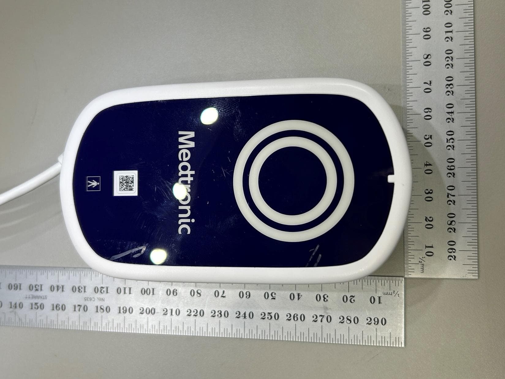
LF526950
Mar 27, 2026MyCareLink Home Communicator Model 26950
Equipment Class
DTS - Digital Transmission System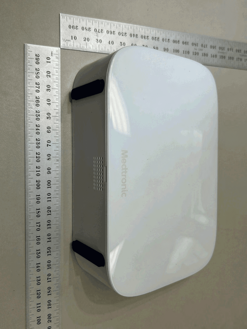
LF526900
Mar 27, 2026MyCareLink Home Communicator Model 26900
Equipment Class
DTS - Digital Transmission System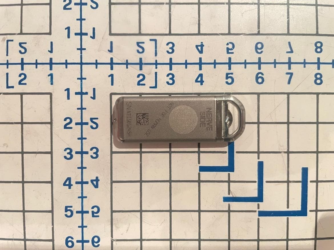
LF5P7850N
Sep 24, 2023Implantable Neurostimulator
Equipment Class
DCD - Part 15 Low Power Transmitter Below 1705 kHz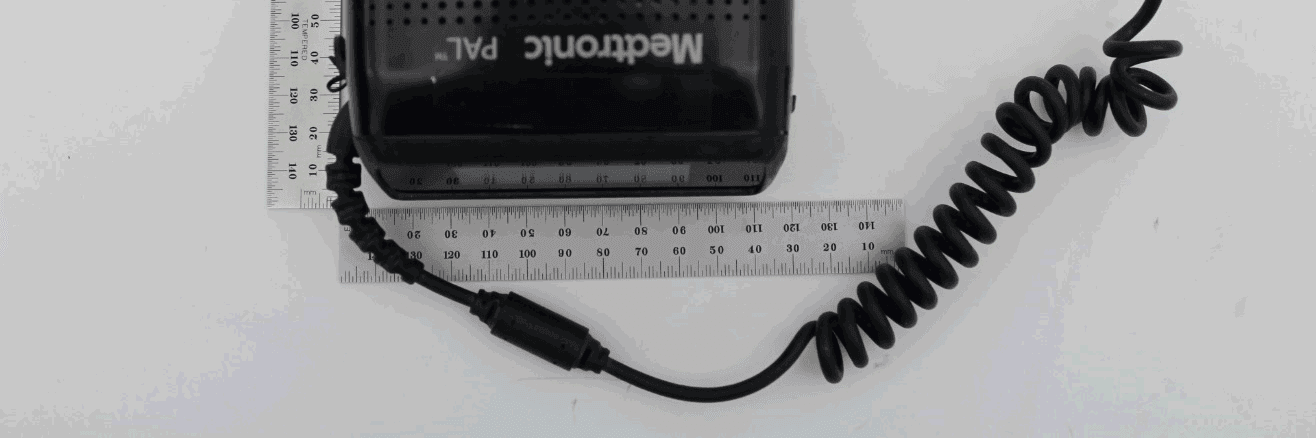
LF5MCS3101CO
May 14, 2020MCS3101CO
Equipment Class
DTS - Digital Transmission System