LF52696Patient Assistant Medical Device
Medtronic, Inc.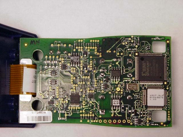
Click to zoom
Application Details
- Equipment Class
- DXX - Part 15 Low Power Communication Device Transmitter
- Date of Grant
- Apr 03, 2003
- Application Purpose
- Original Equipment
- Date of Application
- Apr 03, 2003
- Equipment Note
- Patient Assistant Medical Device
- Frequency Range
- 0.17500000 - 0.17500000
- Company
- Medtronic, Inc.
- Country
- United States
Documents & Files
Document Text
Text extracted from the exhibit documents filed with the FCC. Open a document above to read the original.
Users Manual
220875001Rev APrinting instructions: doc#163256; refer to “Implant man.” row in the applicable table. 220875_fcv.fm 3/13/03 10:11 am UC200203829 EN 4.625 x 6 inches (117 mm x 152 mm) Medtronic Confidential implant_R02 MODEL 2696 INCHECK TM Patient Assistant Caution: Investigational device. Limited by federal law (USA) to investigational use. / Physician’s manual 220875001Rev APrinting instructions: doc#163256; refer to “Implant man.” row in the applicable table. 220875_fcv.fm 3/13/03 10:11 am UC200203829 EN 4.625 x 6 inches (117 mm x 152 mm) Medtronic Confidential implant_R02 Explanation of symbols on the packaging and literature w Attention: See accompanying documentation y Type BF equipment Battery polarity as shown n Serial number i Storage temperature c For United States audiences only Caution:Federal Law (USA) restricts this device to sale by or on the order of a physician Medical device Telemetry (communication signal) status light lit only 220875001Rev APrinting instructions: doc#163256; refer to “Implant man.” row in the applicable table. 220875_fcv.fm 3/13/03 10:11 am UC200203829 EN 4.625 x 6 inches (117 mm x 152 mm) Medtronic Confidential implant_R02 Explanation of symbols on the device Query button (Press to request implanted device to check for AF) OK symbol (AF is not present) AF symbol (AF is present) Therapy button (Press to instruct implanted device to deliver atrial cardioversion therapy) Record Symptoms button (Press to instruct the implanted device to record cardiac activity) Record symbol (recorded cardiac activity) y Type BF equipment Low Batteries symbol Battery polarity as shown w Attention: See accompanying documents c For United States audiences only Caution:Federal Law (USA) restricts this device to sale by or on the order of a physician AF? only 220875001Rev APrinting instructions: doc#163256; refer to “Implant man.” row in the applicable table. 220875_fcv.fm 3/13/03 10:11 am UC200203829 EN 4.625 x 6 inches (117 mm x 152 mm) Medtronic Confidential implant_R02 5 220875001Rev APrinting instructions: doc#163256; refer to “Implant man.” row in the applicable table. 220875TOC.fm 3/13/03 10:11 am UC200203829 EN 4.625 x 6 inches (117 mm x 152 mm) Medtronic Confidential implant_R02 Table of contents 1 Description and intended use7 2 Contents of the Patient Assistant box8 2.1 Inspection9 2.2 Installation and setup9 3 Checking the patient’s heart rhythm9 3.1 How to check the patient’s heart rhythm9 3.2 Response when a query is requested12 4 Requesting atrial cardioversion therapy13 4.1 How to request cardioversion therapy13 4.2 Response when therapy is requested15 4.3 When the Therapy button will appear16 4.4 If therapy is not delivered16 5 Recording cardiac information17 5.1 How to record cardiac information17 5.2 Response when record symptoms is requested18 6 Battery information19 6.1 Replacement batteries19 6.2 When to install batteries19 6.3 How to install new batteries20 7 Maintenance21 7.1 Care and handling21 7.2 Cleaning22 7.3 Service22 6 220875001Rev APrinting instructions: doc#163256; refer to “Implant man.” row in the applicable table. 220875TOC.fm 3/13/03 10:11 am UC200203829 EN 4.625 x 6 inches (117 mm x 152 mm) Medtronic Confidential implant_R02 7.4 Disposal22 8 Troubleshooting23 9 Specifications25 9.1 Device specifications25 9.2 Safety and compatibility standards26 7 220875001Rev APrinting instructions: doc#163256; refer to “Implant man.” row in the applicable table. 220875_CH.fm 3/13/03 10:11 am UC200203829 EN 4.625 x 6 inches (117 mm x 152 mm) Medtronic Confidential implant_R02 1 Description and intended use The Model 2696 InCheck TM Patient Assistant shown on Figure 1 is a hand-held, battery powered, radio frequency communication device. The Patient Assistant communicates with certain implantable Medtronic cardiac devices that provide patient- activated features. See the manual for the implanted device for compatibility information. The Patient Assistant can send simple programming commands to the implanted device, and receive and display information about the patient’s cardiac rhythm. Figure 1.Patient Assistant (Not actual size) Intended use –The Patient Assistant is intended for unsupervised patient use away from a hospital or clinic. The Patient Assistant activates one or more of the patient management features in the implanted device, depending on the implanted device model and the programmed features: ■ To verify whether the implanted device has detected a suspected atrial arrhythmia. AF? Query button, press to check for AT/AF episode detection Record Symptoms button, press to record cardiac event data Telemetry status light Wrist strap connector Symbol and button display area 8 220875001Rev APrinting instructions: doc#163256; refer to “Implant man.” row in the applicable table. 220875_CH.fm 3/13/03 10:11 am UC200203829 EN 4.625 x 6 inches (117 mm x 152 mm) Medtronic Confidential implant_R02 ■ To initiate recording of cardiac event data in the implanted device memory. ■ To request atrial cardioversion therapy, if supported by the implanted device and patient activated therapy has been previously programmed by the physician. Therapy is allowed when the implanted device is currently detecting an atrial arrhythmia episode and all conditions for delivering therapy have been met. Note: ■ Ventricular arrhythmia therapy cannot be patient activated using the Patient Assistant. 2 Contents of the Patient Assistant box The following should be found in the Patient Assistant box: ■ One Patient Assistant ■ Two N-size 1.5 V batteries ■ One carrying case ■ One wrist strap ■ One physician’s manual ■ One quick reference guide/patient ID card ■ Two warranty cards (USA and outside USA) ■ One patient manual The Patient manual includes blank lines in sections 3 and 7 for the patient’s prescription information. This information includes when to use the Patient Assistant, which button to press and what actions to take for each reply. 9 220875001Rev APrinting instructions: …
Text truncated - open the document above for the full version.
Cover Letter(s)
TRP INC. April 3, 2002 Federal Communications Commission 7435 Oakland Mills Rd Columbia, MD 21036 Re: Application for TCB Grant of Certification for FCC ID: LF52696 Gentlemen: Transmitted herewith is an application for certification of a device for patient assistence. The patient assistant is a medical device that incorporates a low frequency telemetry link for the purpose of commanding and querying of an implanted device. Once the requested function is completed, capability for further assisting the patient with a graphical presentation is possible. Since the device is used for medical diagnostic test purposes, emissions from the digital electronics associated with it are exempt underthe provisions of Section 15.103(c). Sincerely, Phillip Inglis Consultant to Medtronic 14085 Howard Rd Dayton, MD 21036
Cover Letter(s)
April 3, 2003 Federal Communications Commission 7435 Oakland Mills Rd Columbia, MD 21036 Re: Request for Confidentiality for FCC ID:LF52 696 Pursuant to Sections 0.457(d)(l)(ii) and 0.459 of the Commission’s Rules, Medtronic Incorporated (Applicant) hereby requests post grant confidential treatment of information accompanying their submission for certification as outlined below: - Schematics - Block Diagram - Technical Circuit Description The above materials contain trade secrets and proprietary information not customarily released to the public. The public disclosure of these matters would be harmful to the Applicant and provide unjustified benefits to its competitors. The Applicant understands that pursuant to Rule 0.457(d)(1)(ii), disclosure of the application and all information contained in the application for grant of certification for the above FCC ID will not be made before the date of the Grant for this Application. Sincerely, Phillip Inglis Consultant to Medtronic Inc. 14085 Howard Rd Dayton, MD 21036
External Photos
External photos are contained in the test report as shown on the test site.
ID Label/Location Info
PLXS-TG RELEASED 03/07/03
ID Label/Location Info
FCC ID label location: Label Location
Test Report
File No. NC300445.2, Page 1 of 8 TÜV PRODUCT SERVICE INC 19333 Wild Mountain Road Taylors Falls MN 55084-1758 Tel: 651 638 0297 Fax: 651 638 0298 Rev.No 1.0 PRODUCT SERVICE TEST RESULT SUMMARY EN 300 330-2 V1.1.1: 2001 Subclauses 7.2, 7.3, 7.4 MANUFACTURER'S NAME Medtronic NAME OF EQUIPMENT Patient Assistant MODEL NUMBER 2696 TYPE OF EQUIPMENT Pocket-sized remote communications device MANUFACTURER'S ADDRESS 7000 Central Avenue NE, MS CW300 Minneapolis MN 55432-3576 TEST REPORT NUMBER NC300445.2 TEST DATE 03 February 2003 According to testing performed at TÜV Product Service Inc, the above-mentioned unit is in compliance with the emission requirements defined in European Telecommunication Standard EN 300 330. It is the manufacturer's responsibility to assure that additional production units of this model are manufactured with identical electrical and mechanical characteristics. Any modifications necessary for compliance made during testing on the above mentioned date(s) must be implemented in all production units for compliance to be maintained. TÜV Product Service Inc, as an independent testing laboratory, declares that the equipment tested as specified above conforms to the emission requirements of European Telecommunication Standard EN 300 330: "Electromagnetic Compatibility and Radio Spectrum Matters (ERM); Short Range Devices (SRD); Technical Characteristics and Test Methods for Radio Equipment in the Frequency Range 9 kHz to 25 MHz and Inductive Loop Systems in the Frequency Range 9 kHz to 30 MHz.” Date: 14 March 2003 Location: Taylors Falls MN Tested By: T. K. Swanson USA R. M. Johnson Technical Writer Not Transferable File No. NC300445.2, Page 2 of 8 TÜV PRODUCT SERVICE INC 19333 Wild Mountain Road Taylors Falls MN 55084-1758 Tel: 651 638 0297 Fax: 651 638 0298 Rev.No 1.0 PRODUCT SERVICE D I R E C T O R Y / SUB-CLAUSE PARAMETER TO BE MEASURED PAGE Page(s) A) Documentation Test Result Summary 1 Directory/Parameters to be measured 2 - 8 Test Setup Photos A1 – A3 The complete list of measurements called for in EN 300 330 is given below. Transmitter parameters - Ambient temperature .....20 ° C Relative humidity .....22% 7.2.1 Transmitter Carrier Output Levels 3 7.2.2 RF Carrier Current Class 3 Only N/A 7.2.3 Radiated E-Field Class 4 Only N/A 7.3.1 Permitted Frequency Range of Modulation bandwidth 4 7.4.2 Conducted Spurious Emissions (Operating) Class 3 Only N/A 7.4.2 Conducted Spurious Emissions (Standby) Class 3 Only N/A 7.4.3 Radiated Field Strength (Transmit < 30 MHz) 5 7.4.3 Radiated Field Strength (Standby < 30 MHz) 5 7.4.4 Radiated Field Strength (Transmit > 30 MHz) 6 7.4.4 Radiated Field Strength (Standby > 30 MHz) 6 Receiver parameters - 8.1.2 Receiver Spurious Radiation (Frequencies < 30 MHz) N/A 8.1.2 Receiver Spurious Radiation (Frequencies > 30 MHz) N/A File No. NC300445.2, Page 3 of 8 TÜV PRODUCT SERVICE INC 19333 Wild Mountain Road Taylors Falls MN 55084-1758 Tel: 651 638 0297 Fax: 651 638 0298 Rev.No 1.0 PRODUCT SERVICE H-FIELD FIELD STRENGTH - SUB-CLAUSE 7.2.1 (Class 1) Rated field strength (maximum) -15.5 dB μ A/m at 10 metres Test conditions Nominal System Operating Frequency: 200.0 kHz Maximum Transmitter Field Strength (dBμA/m) T nom (..20...) ° C Final 10 Metre 10 Metre Limit Margin of compliance -15.5 35.99 51.49 Maximum deviation from rated output under normal test conditions (dB) Measurement uncertainty (dBμA/m) ±1 The noise floor measurement at 10 metres is –21.5dBuA/m. LIMIT SUB-CLAUSE 7.2.1.3 Frequency range - (MHz) H-field field strength limit (Hf) - dBμA/m at 10 m 0,009 ≤ f < 0,03 72 or per note on loop coil antenna area 0,03 ≤ f < 0,07 0,119≤ f < 0,135 72 at 0,03 MHz descending 3 dB/oct or per note on loop coil antenna area 0,05975 ≤ f <0,06025 0,07≤ f < 0,119 42 0,135 ≤ f < 1,0 1,0 ≤ f < 4,642 4,642 ≤ f < 30 37,7 at 0,135 MHz descending 3 dB/oct 29 at 1,0 MHz descending 9 dB/oct 9 6,765 ≤ f ≤ 6,795 (ISM) 13,553 ≤ f ≤ 13,567 (ISM) 26,957 ≤ f ≤ 27,283 (ISM) 42 REFERENCE NUMBER(S) OF TEST EQUIPMENT USED (for reference see test equipment listing) 1,2,3 Ambient temperature ......20. ° C Relative humidity ......22% File No. NC300445.2, Page 4 of 8 TÜV PRODUCT SERVICE INC 19333 Wild Mountain Road Taylors Falls MN 55084-1758 Tel: 651 638 0297 Fax: 651 638 0298 Rev.No 1.0 PRODUCT SERVICE RF CARRIER CURRENT - SUB-CLAUSE 7.2.2 (Class 2) N/A RADIATED E-FIELD, FIELD STRENGTH (measured as H-field) - SUB-CLAUSE 7.2.3 (Class 4) N/A PERMITTED FREQUENCY RANGE OF MODULATION BANDWIDTH - SUB-CLAUSE 7.3.1 Test not applicable since peak fundamental level is below the spurious emission limit. CONDUCTED SPURIOUS EMISSIONS (Operating)- SUB-CLAUSE 7.4.2 (Class 3) N/A CONDUCTED SPURIOUS EMISSIONS (Standby) - SUB-CLAUSE 7.4.2 (Class 3) N/A File No. NC300445.2, Page 5 of 8 TÜV PRODUCT SERVICE INC 19333 Wild Mountain Road Taylors Falls MN 55084-1758 Tel: 651 638 0297 Fax: 651 638 0298 Rev.No 1.0 PRODUCT SERVICE TRANSMITTER RADIATED SPURIOUS EMISSIONS (Transmit < 30 MHz) - SUB-CLAUSE 7.4.3 Transmit spec limit Freq. 1 Meter 3 Meter 10 M 10 M dBuA/m Limit Margin MHz dBuV/m dBuV/m dBuV/m dBuA/m 300 330 dBuA/m 0.15 72 60 34 -17.5 14.76452881 32.2645288 0.6 57 40 16 -35.5 8.735560259 44.2355603 1 51 30 6 -45.5 6.513989065 52.0139891 Transmitter operating with normal internal modulation. LIMIT SUB-CLAUSE 7.4.3.2 State Frequency 9 kHz ≤ f < 10 MHz Frequency 10 MHz ≤ f < 30 MHz Transmit 27 dBμA/m descending 3 dB/oct -3,5 dBμA/m REFERENCE NUMBER(S) OF TEST EQUIPMENT USED (for reference see test equipment listing) 1,2,3 Ambient temperature ......20. ° C Relative humidity ......22% TRANSMITTER RADIATED SPURIOUS EMISSIONS (standby < 30 MHz) - SUB-CLAUSE 7.4.3 No spurious emissions detected in standby mode below 30 MHz. LIMIT SUB-CLAUSE 7.4.3.2 State Frequency 9 kHz ≤ f < 10 MHz Frequency 10 MHz ≤ f < 30 MHz Standby 6 dBμA/m descending 3 dB/oct -24,5 dBμA/m REFERENCE NUMBER(S) OF TEST EQUIPMENT USED (for reference see test equipment listing) 1,2,3 Ambient temperature ......20. ° C Relative humidity…
Text truncated - open the document above for the full version.
Test Report
Addendum to TUV test report. This sheet shows the calculations of field strength based on the magnetic field strength measurements performed by TUV Product Service of Taylor Falls Mn as detailed in their measurement report. TRANSMITTER RADIATED EMISSIONS Frequency DBuV/m DBuV/m DBuV/mFS uV/m FS uV/m FS Limit uV/m MHz 1 m 3m 10m 10 m 300m 300m 0.15 72 60 34 50 0.05 16 0.60 57 40 16 6.3 0.07 4.0 1.0 51 30 6 2.0 0.0062.4 Extrapolation rates are based on inverse square roll off of field strength with distance. Only the highest emissions were calculated with the level being approximately 38 dB below the applicable Part 15 limit. From the above it is concluded that the unit complies with the FCC rules Subpart C Section 15.209 for intentional radiators.
Test Setup Photos
Test site photos are contained in the test report.
Contact Information
Applicant
Guillaume Girard(Sr. RF Regulatory Program Manager)
Technical Contact
TRP IncPhillip Inglis
[email protected]410 531 3439
14085 Howard Rd · Dayton, Maryland · United States
Non-Technical Contact
TRP IncPhillip Inglis
[email protected]410 531 3439
Test Firm
TUV SUD America - Product ServiceJoel Schneider
Technical Specifications
| # | Rule Parts | Frequency Range | Power Output |
|---|---|---|---|
| 1 | 15C | 0.175 MHz - 0.175 MHz | - |
Other Applications from Medtronic, Inc.
LF5BLEIMPLANT5
Jul 09, 2026Confirma DR/SR MRI SureScan, Effectra DR/SR MRI SureScan, Refina CSP DR/SR MRI SureScan, Restoria CSP DR/SR MRI SureScan, ReSyncra CSP DR MRI SureScan, HarmoniaBP DR MRI SureScan
Equipment Class
DTS - Digital Transmission System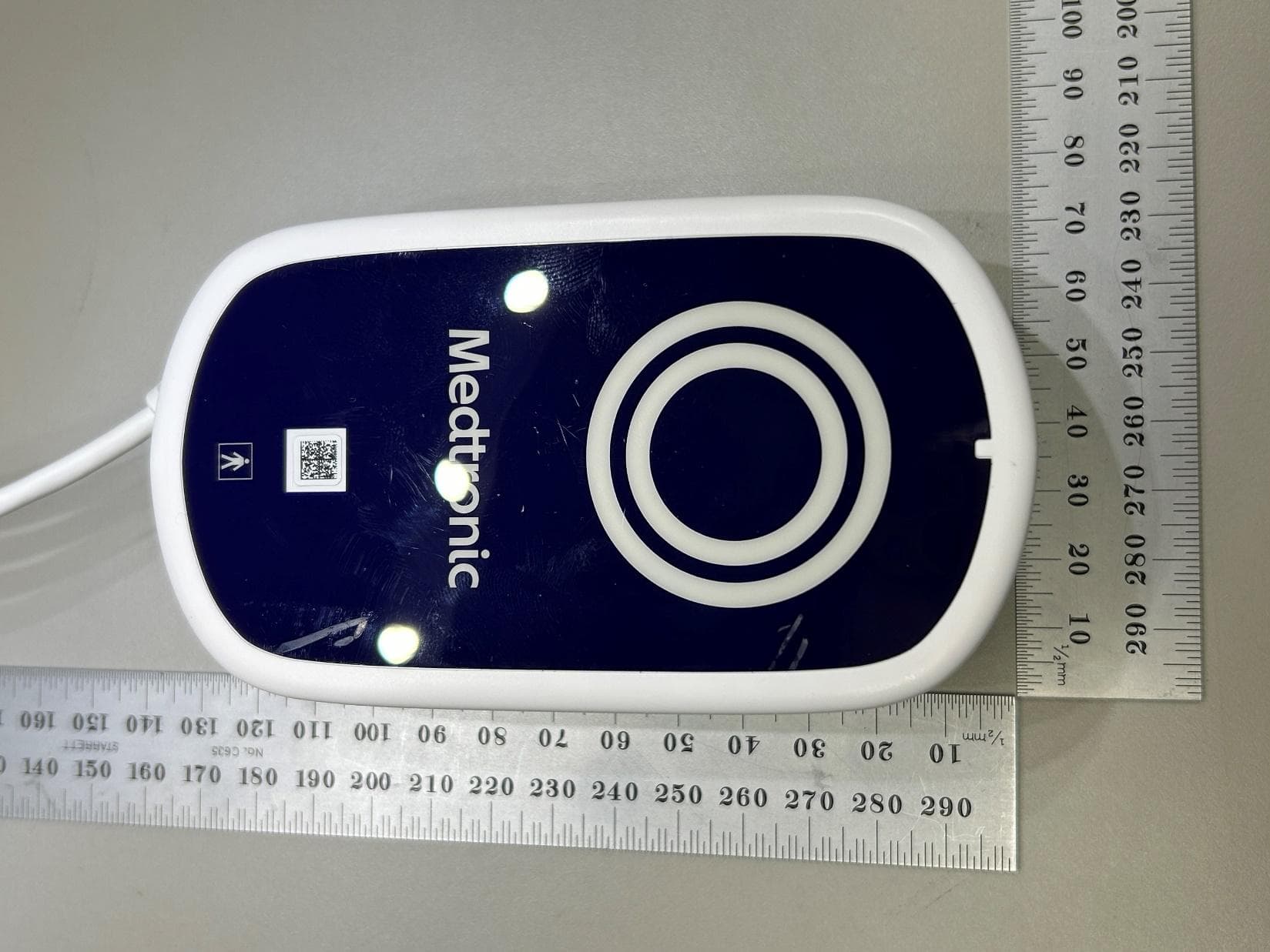
LF526950
Mar 27, 2026MyCareLink Home Communicator Model 26950
Equipment Class
DTS - Digital Transmission System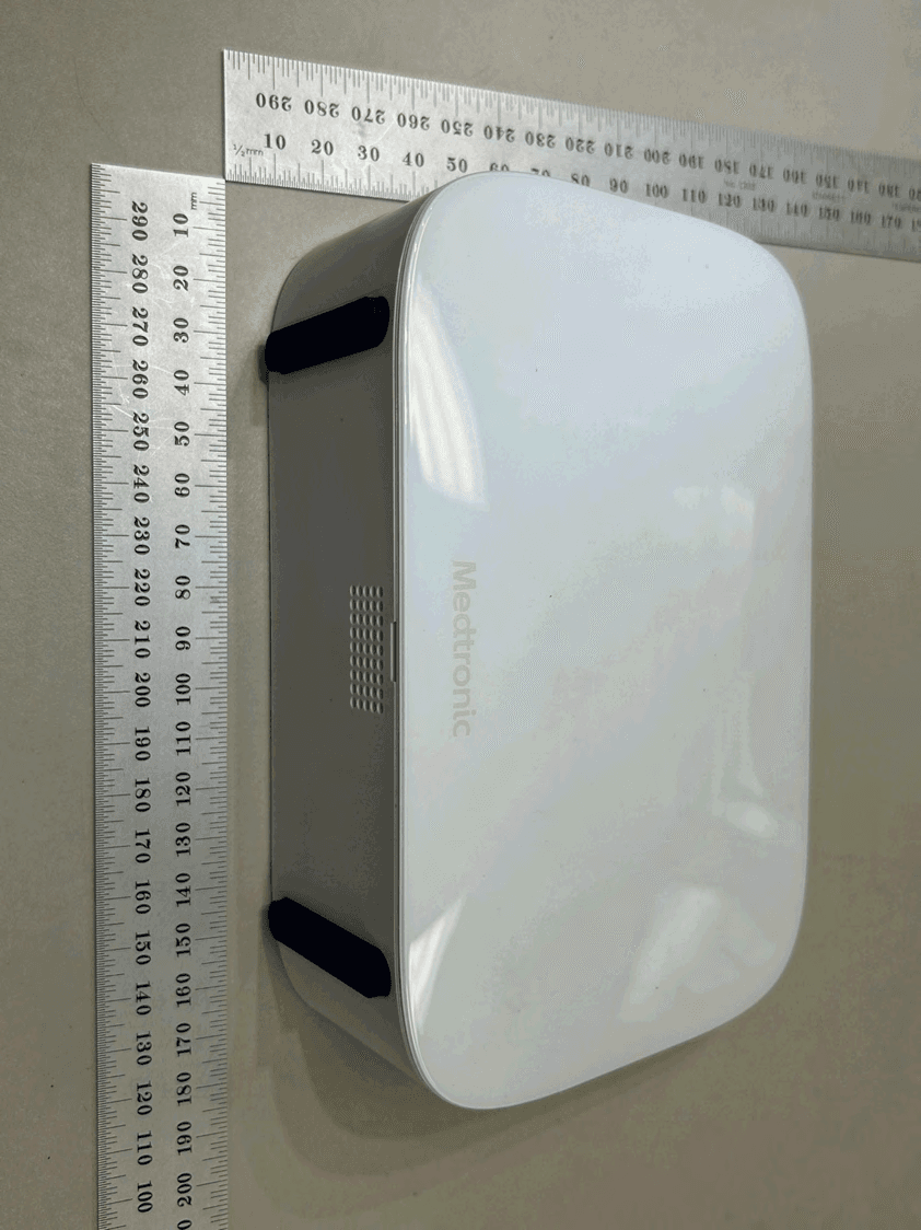
LF526900
Mar 27, 2026MyCareLink Home Communicator Model 26900
Equipment Class
DTS - Digital Transmission System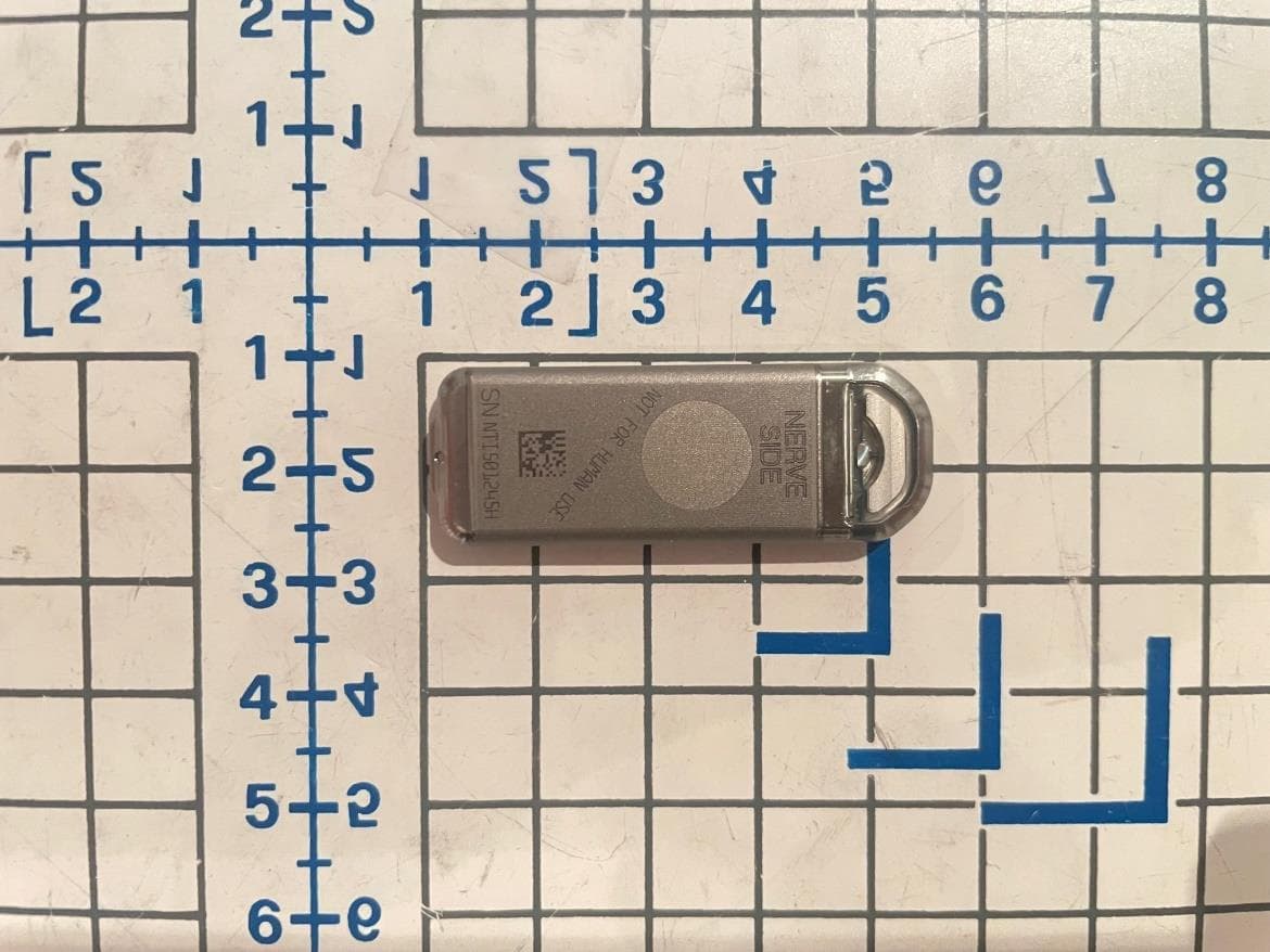
LF5P7850N
Sep 24, 2023Implantable Neurostimulator
Equipment Class
DCD - Part 15 Low Power Transmitter Below 1705 kHz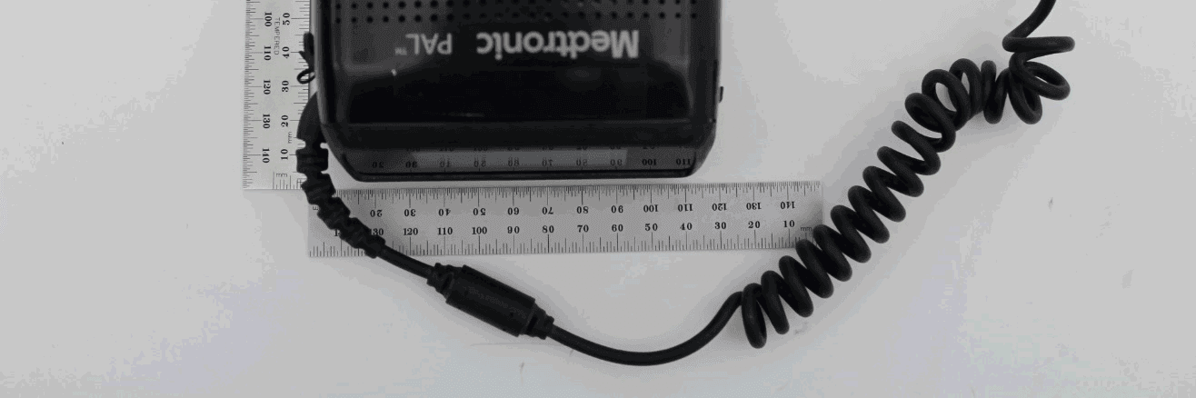
LF5MCS3101CO
May 14, 2020MCS3101CO
Equipment Class
DTS - Digital Transmission System