LF537751Patient Recharge System (INSR)
Medtronic, Inc.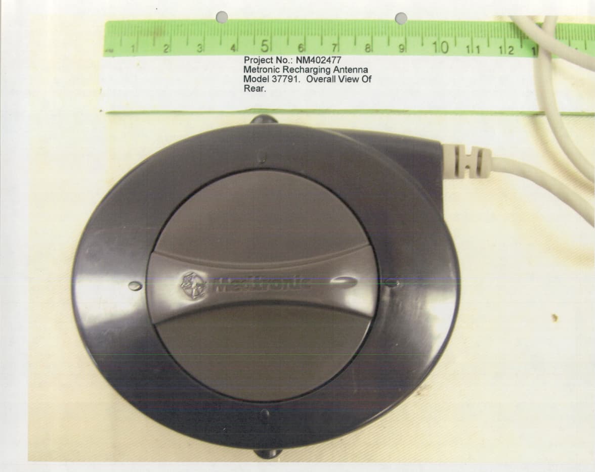
Click to zoom
Application Details
- Equipment Class
- DCD - Part 15 Low Power Transmitter Below 1705 kHz
- Date of Grant
- Apr 28, 2005
- Application Purpose
- Original Equipment
- Date of Application
- Apr 28, 2005
- Equipment Note
- Patient Recharge System (INSR)
- Frequency Range
- 0.17500000 - 0.17500000
- Company
- Medtronic, Inc.
- Country
- United States
Documents & Files
Document Text
Text extracted from the exhibit documents filed with the FCC. Open a document above to read the original.
Users Manual
Neurological Medtronic Confidential Title Model 37751 INSR patient manual Medtronic Confidential This Document is the Property of Medtronic, Inc. and must be accounted for. Information hereon is confidential. DO NOT reproduce it, reveal it to unauthorized persons or send it outside Medtronic without proper authorization. Writer Theresa King-Hunter Date 24 August 2004 Part No. Part No. Rev Comments A08366001 A Global market release Page 1 Form MEDN-0043 version 6.0 DO NOT PRINT THIS FORM WHEN PRINTING THE LITERATURE PIECE. D O NOT COUNT THIS FORM IN THE LITERATURE PIECE PAGE COUNT. R EVISION HISTORY: SEE PDM WEBSITE FOR INFORMATION. 1. Materials: Covers • Grade #1, 80 lb. white gloss coated cover stock, minimum brightness level: 89 Text • 60 lb. white smooth opaque text stock Labels • N/A 2. Colors: To confirm all colors, graphics and text, refer to electronic file Front Cover • 4-color cover and solid gloss varnish Back Cover • Black text and graphics; solid gloss varnish Body • 2-color text and graphics (PMS 301, black, percentages of PMS 301 or percentages of black) Labels • N/A 3. Size: 4.6′′ ± 0.2 (w) x 6.0′′ ± 0.2 (h) 4. Type of Binding: Clear plastic coil, MWE lay-flat, or perfect bound 5. Other: • Cover and text whiteness must match visually. 6. Literature Piece Page Count (Including covers, excluding this form): 86 7. Note to print supplier: Supplier may add up to three blank pages at the end of the document before the back cover sheet as needed. If more are required, contact the purchasing agent. 8. Vendor-supplied information may appear at an appropriate location on the literature piece (eg, part number, bar code, etc.). 9. Graphics Content and Layout to be as shown and per Medtronic electronic file that is supplied (stored) by Medtronic Neuro. PatntFC.fm 8/23/04 7:57 am Size 4.625" x 6.0" (117 mm x 152 mm) UC200xxxxxx EN A08366001Rev X Printing instructions: Medtronic Confidential NeuroPatntR00 RECHARGER37751 Charging System user manual c Rx Only 2005 PatntFC.fm 8/23/04 7:58 am Size 4.625" x 6.0" (117 mm x 152 mm) UC200xxxxxx EN A08366001Rev X Printing instructions: Medtronic Confidential NeuroPatntR00 Medtronic ® , Restore™, and SoftStart™ are trademarks of Medtronic, Inc. c FCC Information The following is communications regulation information on the Model 37751 Patient Programmer. FCC ID: LF537751 This device complies with part 15 Rules. Operation is subject to the following two conditions: (1) this device may not cause harmful interference and (2) this device must accept any interference received, including interference that may cause undesired operation. IMPORTANT: Changes or modifications to this product not authorized by Medtronic, Inc., could void the FCC Certification and negate your authority to operate this product. Printing instructions: PatntTOC.fm 8/23/04 7:58 am Size 4.625" x 6.0" (117 mm x 152 mm) UC200xxxxxx EN A08366001Rev X 37751 03/2005 English Medtronic Confidential NeuroPatntR00 Contents 3 Contents Label symbols 6 1Introduction9 Purpose of the device 10 Warnings 10 Precautions 11 How to use this manual 13 Parts of your charging system 15 How your charging system works 17 Recharger keys and screens 19 Recharger keys 19 Recharger screens 21 2 Using your charging system 25 Battery and charging information 26 Recharger and Neurostimulator 26 Recharger 27 Neurostimulator 28 Neurostimulator battery status 29 Charging your neurostimulator battery 32 A08366001Rev X PatntTOC.fm 8/23/04 7:58 am Size 4.625" x 6.0" (117 mm x 152 mm) UC200xxxxxx EN Printing instructions: English 37751 03/2005 Medtronic Confidential NeuroPatntR00 Contents 4 Turning the neurostimulator ON and OFF while charging 39 Accessories 41 Using the recharger pouch 41 Using the charging system carrying case 41 Identification label 41 3 Troubleshooting 43 Recharger screens 44 Warning screens 44 Information screens 49 Possible problems and solutions 56 User assistance 63 4 Maintenance 65 Recharger maintenance tasks 66 Checking the recharger battery 67 Charging your recharger battery 69 Cleaning and care 72 Safety and technical checks 73 Battery and device disposal 75 Declaration of conformity 75 Printing instructions: PatntTOC.fm 8/23/04 7:58 am Size 4.625" x 6.0" (117 mm x 152 mm) UC200xxxxxx EN A08366001Rev X 37751 03/2005 English Medtronic Confidential NeuroPatntR00 Contents 5 Specifications 76 Glossary 78 Index 80 A08366001Rev X PatntSym.fm 8/23/04 7:58 am Size 4.625" x 6.0" (117 mm x 152 mm) UC200xxxxxx EN Printing instructions: English 37751 03/2005 Medtronic Confidential NeuroPatntR03 Label symbols 6 Label symbols Explanation of symbols on products and packaging. Refer to the appropriate product to see symbols that apply. CE 0123 Conformité Européenne (European Conformity). This symbol means that the device fully complies with AIMD Directive 90/385/EEC (NB 0123) and R&TTE Directive 1999/5/EC. The use of this device might be subject to individual country licensing regimes in Europe. w Caution: consult accompanying documents n Serial number Storage temperature Relative humidity Printing instructions: PatntSym.fm 8/23/04 7:58 am Size 4.625" x 6.0" (117 mm x 152 mm) UC200xxxxxx EN A08366001Rev X 37751 03/2005 English Medtronic Confidential NeuroPatntR03 Label symbols 7 Atmospheric pressure y IEC 60601-1/EN60601-1, Type BF equipment L Non-ionizing electromagnetic radiation Class II equipment System meets the applicable Canadian [C22.2-601.1-M90 (R2001)] and US (UL 60601-1:2003) electrical safety standard requirements. cFor USA audiences only kPa A08366001Rev X PatntSym.fm 8/23/04 7:58 am Size 4.625" x 6.0" (117 mm x 152 mm) UC200xxxxxx EN Printing instructions: English 37751 03/2005 Medtronic Confidential NeuroPatntR03 Label symbols 8 PatntCh01.fm 8/23/04 7:58 am Size 4.625" x 6.0" (117 mm x 152 mm) UC200xxxxxx EN A08366001Rev X Printing instructions: Medtronic Confidential NeuroPatntR03 1 Introduction PatntCh01.fm 8/23/04 7:58 am Size 4.625" x 6.0" (117 mm x 152 mm) UC200xxxxxx EN A08366001Rev X …
Text truncated - open the document above for the full version.
Block Diagram
Block Diagram Description uP 2 Li+ Batteries LCD Lighting Receive Transmit System Memory / I/O Crystal 9.8304MHz Audio Transducer Push Button Matrix LCD Module RTC Crystal 32.768 kHz IRDA Desktop Charger Connector CHARGE I Measure VBASE (10V Power) READY BAT_CHRG_EN DOCK_DETECT 12V Supply 3.3V Analog Supply 3.3V Digital Supply V_12 V_BAT BURST_MODE 3.3V_CONTROL V_3.3 Analog V_3.3 Telemetry Antenna Recharge Coil TEL_EN UPLINK_EN Temp Sensor PTEMP_SENSOR HV_CTRL I_RECHRG Software Loading Port EXT_ANT Recharge Antenna, Model 37791 A/D A/D A/D BATTERY A/D AVCC Reset Button Digtal Board INSR Board Q13 Bridge Circuit PTEMP_TEST A/D 3V Reference A/D 3V Reference SHDN_HV 3V Reference Digtal Board INSR Board GND Recharge Frequency: 9kHz Transmit Frequency: 175kHz RESTORE INSR
Cover Letter(s)
Attn: Director of Certification 19 April 2005 Federal Communications Commission 7435 Oakland Mills Road Columbia, MD 21046 Attn: Reviewing Engineer 19 April 2005 , INSR, FCC ID: LF537751
Cover Letter(s)
American Telecommunications Certification Body Inc. 6731 Whittier Ave, McLean, VA 22101 April 21, 2005 RE: Medtronic Inc. FCC ID: LF537751 After a review of the submitted information, I have a few comments on the above referenced Application. 1) According to ANSI C63.4 (13.1.4.1), Portable devices are required to be positioned in each of 3 axis and measured to obtain worse case. This does not appear to have been done. Please review? 2) It appears the fundamental was measured in average mode. Please note that there is also a limit on the peak emissions that is 20 dB above the average limit (15.35). It is also unsure of what type of modulation was present but information in the operational description suggests this will be pulsed emissions. Therefore the FCC expects the device to have been measured in peak mode and corrected mathematically for average. Please provide further information as necessary. For instance, what was the peak to average ratio. What type of modulation was present. Note that the operational description (section 1.4.1) mentions pulse duration and pulse position as possible encoding schemes. This would suggest that peak emissions corrected for worse case average factors should have been applied. 3) The device appears to have pulse width and amplitude adjustments from the programmer. How do these settings affect the RF output (waveform)? Are these sent only as data commands to the stimulation device or is the RF envelope affected? For instance is a programming of the amplitude of the stimulation device accomplished by sending data to the stimulation device, or does the programmer TX waveform actually change amplitude as well. Note it appears from information in the operational description that the duty cycle is affected directly based upon the duty cycle entered in the programmer and that the amplitude may also vary according to programming. The device should have been tested at maximum RF output levels as well as maximum duty cycle. Please explain. 4) It appears that the extrapolation of this device would be 46 dB per decade and not 48 dB per decade. Please review and correct as necessary. 5) Please explain how the loop antenna (measurement antenna) was positioned and maximized during test. Loop antennas should be checked positioned in Vertical and Horizontal polarities according to ANSI C63.4 at a 1 meter height. Additionally, Vertical polarity should have been rotated about the Vertical axis to obtain worse case (ANSI C63.4 8.2.1). Antenna positioning can dramatically affect the results. No mention of antenna positioning appears in the report. Please explain. --- Continue on Next Page --- z Page 2 April 21, 2005 6) The recharge circuit (operational description section 5.10.8.2) suggests the recharge circuit can operated from 8.455 to 9.345 kHz. Operation above 9 kHz would be subject to Part 15 for Certification and would require testing and submittal as part of this application. This information does not appear to have been provided. Additionally, note that information in the operational description suggests this field will be much higher than the telemetry field. If operation will be limited only to below 9 KHz, how is compliance to 15.15 assured given the information in the operational description? Timothy R. Johnson Examining Engineer mailto: [email protected] The items indicated above must be submitted before processing can continue on the above referenced application. Failure to provide the requested information may result in application termination. Correspondence should be considered part of the permanent submission and may be viewed from the Internet after a Grant of Equipment Authorization is issued. Please do not respond to this correspondence using the email reply button. In order for your response to be processed expeditiously, you must submit your documents through the AmericanTCB.com website. Also, please note that partial responses increase processing time and should not be submitted. Any questions about the content of this correspondence should be directed to the sender.
Cover Letter(s)
American Telecommunications Certification Body Inc. 6731 Whittier Ave, McLean, VA 22101 April 29, 2005 RE: Medtronic Inc. FCC ID: LF537751 After a review of the submitted information, I have a few comments on the above referenced Application. 1) Earlier information regarding 175 kHz mentioned that the peak to average difference was 8 dB, while the latest corrected report mentions 3 dB. Please confirm the correct ratio. Timothy R. Johnson Examining Engineer mailto: [email protected] The items indicated above must be submitted before processing can continue on the above referenced application. Failure to provide the requested information may result in application termination. Correspondence should be considered part of the permanent submission and may be viewed from the Internet after a Grant of Equipment Authorization is issued. Please do not respond to this correspondence using the email reply button. In order for your response to be processed expeditiously, you must submit your documents through the AmericanTCB.com website. Also, please note that partial responses increase processing time and should not be submitted. Any questions about the content of this correspondence should be directed to the sender.
Cover Letter(s)
TÜV America Inc. Phone: (651) 631-2487 1775 Old Highway 8 NW Fax: (651) 638-0285 Suite 104 E-mail: [email protected] New Brighton, MN 55112 www.TUVamerica.com Management Service • Product Service • Industry Service • Automotive • BABT TÜV America Inc. is a subsidiary of TÜV SÜD Group. 22 April 2005 RE: Medtronic Inc FCC ID: LF537751 In response to ATCB comments on the above referenced application. 1. Page C2 of C2 describes the EUT was examined in 3 orthogonal axes. Test setup photographs indicate the worst case configuration. 2. This is an omission in the test report. Peak measurements were made, and were 8 dB higher than the average measurements. Reports will be corrected and resent. Modulation type was Continuous Wave Amplitude Burst Modulation. 3. The patient programmer is the only device that can adjust the pulse width and amplitude of the implantable neurostimulator (INS). The INSR is only able to turn the INS on and off and recharge. Even though the programmer can adjust these parameters, the RF output of the patient programmer isn't affected because it's just commands that are being transmitted from the programmer to the INS. The pulse width and amplitude adjustments are for the implant's therapy stimulation output. It has no bearing on RF output levels. 4. The report has been corrected to 46 dB/decade. 5. ANSI C63.4 procedures are followed - page C2 of C2 describes procedure used. 6. The recharge circuit operates at the 9 kHz frequency, not at 8 kHz as was originally indicated, and the frequencies can not be transmitted simultaneously. Measurements had been made on the 9 kHz recharge circuit but we had been told that the device operated at less than 9 kHz so had not included the report with the original documents submitted. In addition to the 9 kHz Test Report, the 175 kHz Test Report, Test Setup Photos, Block Diagram, Form 731, RF Exposure Letter, and Technical Description exhibits have been revised accordingly and uploaded at the same time as this correspondence. Please let us know if you require any further information. Thank you. Jolene Murphy Senior Technical Writer [email protected]
Cover Letter(s)
TÜV America Inc. Phone: (651) 631-2487 1775 Old Highway 8 NW Fax: (651) 638-0285 Suite 104 E-mail: [email protected] New Brighton, MN 55112 www.TUVamerica.com Management Service • Product Service • Industry Service • Automotive • BABT TÜV America Inc. is a subsidiary of TÜV SÜD Group. 26 April 2005 RE: Medtronic Inc FCC ID: LF537751 In response to 25 April 2005 ATCB comments on the above referenced application. Both test reports have been revised and uploaded at the same time as this correspondence. Please let us know if you require any further information. Thank you. Jolene Murphy Senior Technical Writer [email protected]
Cover Letter(s)
TÜV America Inc. Phone: (651) 631-2487 1775 Old Highway 8 NW Fax: (651) 638-0285 Suite 104 E-mail: [email protected] New Brighton, MN 55112 www.TUVamerica.com Management Service • Product Service • Industry Service • Automotive • BABT TÜV America Inc. is a subsidiary of TÜV SÜD Group. 29 April 2005 RE: Medtronic Inc FCC ID: LF537751 In response to 29 April 2005 ATCB comments on the above referenced application. The peak to average difference of 3 dB is correct for FCC ID: LF37751. Please let us know if you require any further information. Thank you. Joel T Schneider Senior Engineer
Cover Letter(s)
TÜV America Inc. Phone: (651) 631-2487 Product Service Fax: (651) 638-0285 1775 Old Highway 8 NW E-mail: [email protected] Suite 104 www.TUVamerica.com New Brighton, MN 55112 Management Service • Product Service • Industry Service • Automotive • BABT TÜV America Inc. is a subsidiary of Group TÜV Süddeutschland. TÜV AMERICA INC - PRODUCT SERVICE 19333 WILD MOUNTAIN ROAD TAYLORS FALLS, MINNESOTA 55084-1786 ENGINEERING STATEMENT For Certification of Medtronic Inc Implantable Neurostimulator (INS) Recharger (INSR) Model No: 37751, 37752 FCC ID: LF537751 FRN: 0010-0391-05 The Implantable NeuroStimulator Recharger (INSR) platform design is identified via model 37751. This platform is designed to be the base hardware and software application for the market release product. The model 37752 represents the Patient Recharge System that contains the model 37751, the external power supply, power cord, the recharge belt and carrying case. The FCC ID number was chosen to represent the main communication device, which is the model 37751 (accessories used during testing: external power supply, power cord). The model 37751 will be used to recharge the Implantable Neurostimulator (INS) model 37711, as well as be able to control start and stop stimulation. The external power supply will be used to recharge the INSR batteries, as well as to power the INSR directly. I am an Electromagnetic Compatibility Engineer for TÜV AMERICA INC - PRODUCT SERVICE, Taylors Falls, Minnesota. My education and experience are a matter of record with the Federal Communications Commission. TÜV AMERICA INC - PRODUCT SERVICE has been authorized by Kevin Kelly, Stim Product Development Director, of Medtronic Inc to make Certification measurements and act as the authorized representative in the preparation of applications for registration of the above mentioned equipment. TÜV AMERICA INC - PRODUCT SERVICE is on file with the FCC under Paragraph 2.948 of the FCC Rules. Test data required by the TCB for Certification is included in this report. It is submitted that the above equipment meets the FCC Part 15 Subpart C requirements and Certification is hereby requested. Joel T. Schneider Senior Engineer Minnesota Wild River Lab TÜV America - Product Service Tel: 651 604 4582 Fax: 651 638 0298 [email protected] Dated: 20 April 2005
External Photos
Medtronic Recharging System Medtronic INSR Programmer - Top Medtronic INSR Programmer - Bottom Medtronic INSR Programmer - Front View Medtronic INSR Programmer - Left and Back View Medtronic INSR Programmer - Right and Back View Medtronic INSR Programmer - Antenna Top View Medtronic INSR Programmer - Antenna Bottom View
ID Label/Location Info
Because of the small size of the device, the compliance statement will be placed in the user manual. Label placement (prototype label shown in photo. See label on previous page for final product label).
Internal Photos
Medtronic INSR Programmer - Disassembly View 1 Medtronic INSR Programmer - Disassembly View 2 Medtronic INSR Programmer - Disassembly View 3 Medtronic INSR Programmer - Recharge Board Top Medtronic INSR Programmer - Recharge Board Bottom Medtronic INSR Programmer - Digital Board Top Medtronic INSR Programmer - Digital Board Bottom Medtronic INSR Programmer - Digital Board - LCD Medtronic INSR Programmer - Antenna Disassembly - View 1 Medtronic INSR Programmer - Antenna Disassembly - View 2 Medtronic INSR Programmer - Antenna Disassembly - View 3 Medtronic INSR Programmer - Antenna Disassembly - View 4
Test Report
PRODUCT SERVICE TEST RESULT SUMMARY FCC PART 15 SUBPART C Section 15.209 FCC PART 15 SUBPART C Section 15.207 MANUFACTURER'S NAME Medtronic Neurological NAME OF EQUIPMENT Restore Charging System TYPE OF EQUIPMENT Battery-powered INS Recharger MODEL NUMBER 37751 MANUFACTURER'S ADDRESS 800 53 rd Avenue NE Columbia Heights, MN 55421 TEST REPORT NUMBER WC402493.4 Rev C TEST DATE 07 & 14 June 2004 According to testing performed at TÜV Product Service Inc, the above-mentioned unit is in compliance with the electromagnetic compatibility requirements defined in FCC Part 15 Subpart C, Sections 15.207 and 15.209. It is the manufacturer's responsibility to assure that additional production units of this model are manufactured with identical electrical and mechanical characteristics. Any modifications necessary for compliance made during testing on the above mentioned date(s) must be implemented in all production units for compliance to be maintained. TÜV Product Service Inc, as an independent testing laboratory, declares that the equipment tested as specified above conforms to the requirements of FCC Part 15 Subpart C, Sections 15.207 and 15.209. Date: 26 April 2005 Location: Taylors Falls MN R. M. Johnson T. K. Swanson USA Tested By Reviewed By Not Transferable File No. WC402493.4 Rev C, Page 1 of 13 TÜV PRODUCT SERVICE INC 19333 Wild Mountain Road Taylors Falls MN 55084-1758 Tel: 651 638 0297 Fax: 651 638 0298Rev.No 1.0 PRODUCT SERVICE EMC EMISSION - T E S T R E P O R T Test Report File No. : WC402493.4 Rev C Date of issue: 26 April 2005 Model No. : 37751 Product Name : Restore Charging System Product Type : Battery-powered INS Recharger Applicant : Medtronic Neurological Manufacturer : Medtronic Neurological License holder : Medtronic Neurological Address : 800 53 rd Avenue NE : Columbia Heights, MN 55421 Test Result : Positive Negative Test Project Number : Reference(s) WC402493.4 Rev C Total pages including Appendices 35 TÜV Product Service Inc is a subcontractor to TÜV Product Service, GmbH according to the principles outlined in ISO/IEC Guide 25 and EN 45001. TÜV Product Service Inc reports apply only to the specific samples tested under stated test conditions. It is the manufacturer's responsibility to assure that additional production units of this model are manufactured with identical electrical and mechanical components. TÜV Product Service Inc shall have no liability for any deductions, inferences or generalizations drawn by the client or others from TÜV Product Service Inc issued reports. This report is the confidential property of the client. As a mutual protection to our clients, the public and ourselves, extracts from the test report shall not be reproduced except in full without our written approval. This report shall not be used by the client to claim product endorsement by NVLAP or any agency of the US government. TÜV Product Service Inc and its professional staff hold government and professional organization certifications and are members of AAMI, ACIL, AEA, ANSI, IEEE, NVLAP, and VCCI File No. WC402493.4 Rev C, Page 2 of 13 TÜV PRODUCT SERVICE INC 19333 Wild Mountain Road Taylors Falls MN 55084-1758 Tel: 651 638 0297 Fax: 651 638 0298Rev.No 1.0 PRODUCT SERVICE REVISION RECORD REVISION TOTAL NUMBER OF PAGES DATE DESCRIPTION 29 26 July 2004 Initial Release A 35 20 April 2005 Revisions include: Added conducted and radiated emissions setup photos. Added conducted emissions data and reference to FCC Part 15 Subpart C Section 15.207. B 35 22 April 2005 Revisions include: Page 10 - FCC 15.209 - Radiated emissions (magnetic field) 10 kHz - 30 MHz: Corrected to 46 dB/decade. C 35 26 April 2005 Revisions include: Page 10 - added information about peak detection. File No. WC402493.4 Rev C, Page 3 of 13 TÜV PRODUCT SERVICE INC 19333 Wild Mountain Road Taylors Falls MN 55084-1758 Tel: 651 638 0297 Fax: 651 638 0298Rev.No 1.0 PRODUCT SERVICE D I R E C T O R Y - EMISSIONS Page(s) A) Documentation Test report 1 - 11 Revision Record 2 Directory 3 Test Regulations 4 Deviation from standard / Summary 11 Test-setups (Photos) 12 - 13 Test-setup (drawing) Appendix A B) Test data FCC 15.207 - Conducted emissions 10/150 kHz - 30 MHz 6, 10 FCC 15.209 - Radiated emissions 10 kHz - 30 MHz 6, 10 FCC 15.209 - Radiated emissions 30 MHz - 1000 MHz 7, 10 Interference power 30 MHz - 300 MHz N/A Equivalent Radiated emissions 1 GHz - 18 GHz N/A C) Appendix A Test Data Sheets and Test Setup Drawing(s) A2 – A12 D) Appendix B Constructional Data Form B2 – B8 Product Information Form(s) N/A E) Appendix C Measurement Protocol C1 - C2 File No. WC402493.4 Rev C, Page 4 of 13 TÜV PRODUCT SERVICE INC 19333 Wild Mountain Road Taylors Falls MN 55084-1758 Tel: 651 638 0297 Fax: 651 638 0298Rev.No 1.0 PRODUCT SERVICE EMISSIONS TEST REGULATIONS : The emissions tests were performed according to following regulations: -------------------------------------------------------------------------------- - EN 50081-1 / 1991 - EN 55011 / 1991 - Group 1 - Group 2 - Class A - Class B - EN 55013 / 1990 - EN 55014 / 1987 - Household appliances and similar - Portable tools - Semiconductor devices - EN 55014 / A2:1990 - EN 55014 / 1993 - Household appliances and similar - Portable tools - Semiconductor devices - EN 55015 / 1987 - EN 55015 / A1:1990 - EN 55015 / 1993 - EN 55022 / 1987 - Class A - Class B - EN 55022 / 1994 - Class A - Class B - BS - VCCI - Class A - Class B - FCC Part 15 Subpart C Section 15.209 - FCC Part 15 Subpart C Section 15.207 Conducted Emission Requirements - FCC Part 15 Subpart B - Class A - Class B - CISPR 11 (1990) - Group 1 - Group 2 - Class A - Class B - CISPR 22 (1993) - Class A - Class B File No. WC402493.4 Rev C, Page 5 of 13 TÜV PRODUCT SERVICE INC 19333 Wild Mountain Road Taylors Falls MN 55084-1758 Tel: 651 638 0297 Fax: 651 638 0298Rev.No 1.0 PRODUCT SERVICE Environmental conditions in the lab: Actual Temperature…
Text truncated - open the document above for the full version.
Test Report
PRODUCT SERVICE TEST RESULT SUMMARY FCC PART 15 SUBPART C Section 15.209 MANUFACTURER'S NAME Medtronic Neurological NAME OF EQUIPMENT Restore Charging System TYPE OF EQUIPMENT Battery-powered INS Recharger MODEL NUMBER 37751 MANUFACTURER'S ADDRESS 800 53 rd Avenue NE Columbia Heights, MN 55421 TEST REPORT NUMBER WC402493.1 Rev B TEST DATE 14 June & 12 July 2004 According to testing performed at TÜV Product Service Inc, the above-mentioned unit is in compliance with the electromagnetic compatibility requirements defined in FCC Part 15 Subpart C, Section 15.209. It is the manufacturer's responsibility to assure that additional production units of this model are manufactured with identical electrical and mechanical characteristics. Any modifications necessary for compliance made during testing on the above mentioned date(s) must be implemented in all production units for compliance to be maintained. TÜV Product Service Inc, as an independent testing laboratory, declares that the equipment tested as specified above conforms to the requirements of FCC Part 15 Subpart C, Section 15.209. Date: 26 April 2005 Location: Taylors Falls MN R. M. Johnson T. K. Swanson USA Tested By Reviewed By Not Transferable File No. WC402493.1 Rev B, Page 1 of 13 TÜV PRODUCT SERVICE INC 19333 Wild Mountain Road Taylors Falls MN 55084-1758 Tel: 651 638 0297 Fax: 651 638 0298Rev.No 1.0 PRODUCT SERVICE EMC EMISSION - T E S T R E P O R T Test Report File No. : WC402493.1 Rev B Date of issue: 26 April 2005 Model No. : 37751 Product Name : Restore Charging System Product Type : Battery-powered INS Recharger Applicant : Medtronic Neurological Manufacturer : Medtronic Neurological License holder : Medtronic Neurological Address : 800 53 rd Avenue NE : Columbia Heights, MN 55421 Test Result : Positive Negative Test Project Number : Reference(s) WC402493.1 Rev B Total pages including Appendices 41 TÜV Product Service Inc is a subcontractor to TÜV Product Service, GmbH according to the principles outlined in ISO/IEC Guide 25 and EN 45001. TÜV Product Service Inc reports apply only to the specific samples tested under stated test conditions. It is the manufacturer's responsibility to assure that additional production units of this model are manufactured with identical electrical and mechanical components. TÜV Product Service Inc shall have no liability for any deductions, inferences or generalizations drawn by the client or others from TÜV Product Service Inc issued reports. This report is the confidential property of the client. As a mutual protection to our clients, the public and ourselves, extracts from the test report shall not be reproduced except in full without our written approval. This report shall not be used by the client to claim product endorsement by NVLAP or any agency of the US government. TÜV Product Service Inc and its professional staff hold government and professional organization certifications and are members of AAMI, ACIL, AEA, ANSI, IEEE, NVLAP, and VCCI File No. WC402493.1 Rev B, Page 2 of 13 TÜV PRODUCT SERVICE INC 19333 Wild Mountain Road Taylors Falls MN 55084-1758 Tel: 651 638 0297 Fax: 651 638 0298Rev.No 1.0 PRODUCT SERVICE REVISION RECORD REVISION TOTAL NUMBER OF PAGES DATE DESCRIPTION 29 26 July 2004 Initial Release A 41 22 April 2005 Revisions include: Pages 12-13: Added Test Setup Photos Page 10 - FCC 15.207 - Conducted emissions 150 kHz - 30 MHz: Added test results Page 10 - FCC 15.209 - Radiated emissions (magnetic field) 9 kHz - 30 MHz: Corrected to 48 dB/decade and added peak detection information. B 41 26 April 2005 Revisions include: Page 10 - 52.4 dB/decade fundamental extrapolation. Page A8 - final level of 8 dBuV/m at 300 meters. File No. WC402493.1 Rev B, Page 3 of 13 TÜV PRODUCT SERVICE INC 19333 Wild Mountain Road Taylors Falls MN 55084-1758 Tel: 651 638 0297 Fax: 651 638 0298Rev.No 1.0 PRODUCT SERVICE D I R E C T O R Y - EMISSIONS Page(s) A) Documentation Test report 1 - 10 Revision Record 2 Directory 3 Test Regulations 4 Deviation from standard / Summary 11 Test-setups (Photos) 12 - 13 Test-setup (drawing) Appendix A B) Test data FCC 15.207 - Conducted emissions 10/150 kHz - 30 MHz 6, 10 FCC 15.209 - Radiated emissions 10 kHz - 30 MHz 6, 10 FCC 15.209 - Radiated emissions 30 MHz - 1000 MHz 7, 10 Interference power 30 MHz - 300 MHz N/A Equivalent Radiated emissions 1 GHz - 18 GHz N/A C) Appendix A Test Data Sheets and Test Setup Drawing(s) A1 – A12 D) Appendix B Constructional Data Form B1 – B8 Product Information Form(s) N/A E) Appendix C Measurement Protocol C1 - C2 File No. WC402493.1 Rev B, Page 4 of 13 TÜV PRODUCT SERVICE INC 19333 Wild Mountain Road Taylors Falls MN 55084-1758 Tel: 651 638 0297 Fax: 651 638 0298Rev.No 1.0 PRODUCT SERVICE EMISSIONS TEST REGULATIONS : The emissions tests were performed according to following regulations: -----------------------------------------------------------------------…
Text truncated - open the document above for the full version.
Contact Information
Applicant
Guillaume Girard(Sr. RF Regulatory Program Manager)
Technical Contact
TUV America Inc - Product ServiceJoel T Schneider
[email protected]651-604-4582
19333 Wild Mountain Road · Taylors Falls, Minnesota · United States
Non-Technical Contact
TUV America Inc - Product ServiceJolene Murphy
[email protected]651-638-0271
Test Firm
TUV SUD America - Product ServiceJoel Schneider
Technical Specifications
| # | Rule Parts | Frequency Range | Power Output |
|---|---|---|---|
| 2 | 15C | 0.175 MHz - 0.175 MHz | - |
Other Applications from Medtronic, Inc.
LF5BLEIMPLANT5
Jul 09, 2026Confirma DR/SR MRI SureScan, Effectra DR/SR MRI SureScan, Refina CSP DR/SR MRI SureScan, Restoria CSP DR/SR MRI SureScan, ReSyncra CSP DR MRI SureScan, HarmoniaBP DR MRI SureScan
Equipment Class
DTS - Digital Transmission System
LF526950
Mar 27, 2026MyCareLink Home Communicator Model 26950
Equipment Class
DTS - Digital Transmission System
LF526900
Mar 27, 2026MyCareLink Home Communicator Model 26900
Equipment Class
DTS - Digital Transmission System
LF5P7850N
Sep 24, 2023Implantable Neurostimulator
Equipment Class
DCD - Part 15 Low Power Transmitter Below 1705 kHz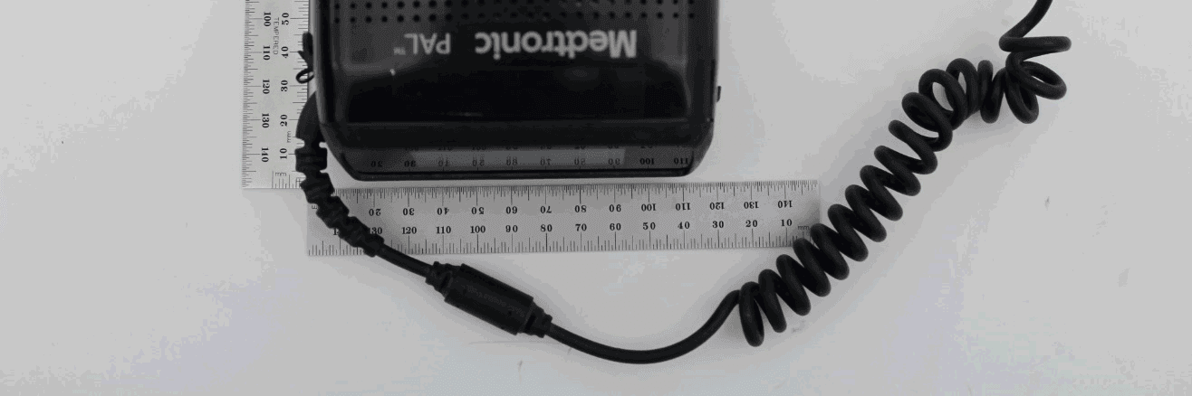
LF5MCS3101CO
May 14, 2020MCS3101CO
Equipment Class
DTS - Digital Transmission System