LF58880T28880T2
Medtronic, Inc.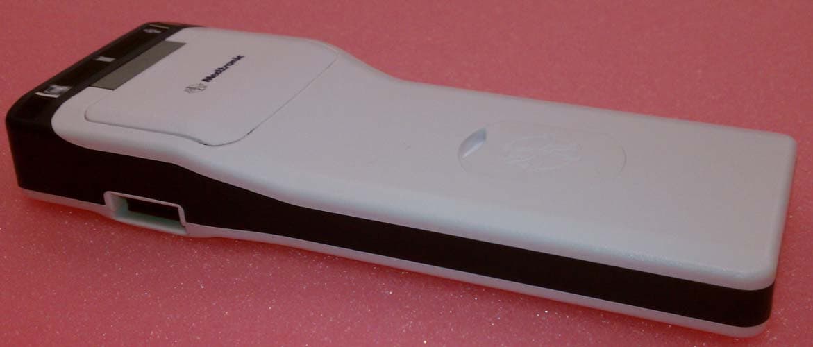
Click to zoom
Application Details
- Equipment Class
- DSS - Part 15 Spread Spectrum Transmitter
- Date of Grant
- Oct 14, 2012
- Application Purpose
- Original Equipment
- Date of Application
- Oct 14, 2012
- Equipment Note
- 8880T2
- Frequency Range
- 2402.00000000 - 2480.00000000
- Company
- Medtronic, Inc.
- Country
- United States
Documents & Files
Document Text
Text extracted from the exhibit documents filed with the FCC. Open a document above to read the original.
Users Manual
Form MEDN-0500 version 3.0 NEUROMODULATION CONFIDENTIAL DOCUMENT/RECORD This document/record is electronically controlled, printed copies are considered uncontrolled. Identifier Version Author Title: Pages: (including this page) APPROVALS Signed By Responsibility Date/Time (GMT) NDHF1205-12133710.0Karyn Van Erem 8880CW 8880T2 Technical Manual for Agency Testing Karyn Van EremTechnical Communications Approver9/27/2012 3:55:45 PM Medtronic Neuromodulation Clinician Programmer 8880CW and Model 8880T2 Telemetry Head Technical Manual ! USA Rx only 2013 Filename Date Time UC200xxxxxx EN 7 x 9 inches (178 mm x 229 mm) Medtronic Confidential HardwareShortManual.xsl - HardwareShortTemplate.fm Template version: 07-06-2012 M937825A001 Rev X 2013- 03 Filename Date Time UC200xxxxxx EN 7 x 9 inches (178 mm x 229 mm) Medtronic Confidential HardwareShortManual.xsl - HardwareShortTemplate.fm Template version: 07-06-2012 M937825A001 Rev X 2013- 03 Label symbols Explanation of symbols on products and packaging. Refer to the appropriate product to see symbols that apply. Consult instructions for use XXX °F XX °C -XX °F -XX °C Temperature limitation Conformité Européenne (European Conformity). This symbol means that the device fully complies with AIMD Directive 90/385/EEC (NB 0123) and R&TTE Directive 1999/5/EC. Manufacturer EC REP Authorized representative in the European community For USA audiences only Non-ionizing electromagnetic radiation IEC 60601-1/EN60601-1, Type BF Equipment Medical – General Medical Equipment as to electrical shock, fire and mechanical hazards only in accordance with ANSI/AAMI ES 60601-1 and CAN/CSA C22.2 No. 60601-1. Do not dispose of this product in the unsorted municipal waste stream. Dispose of this product according to local regulations. See http://recycling.medtronic.com for instructions on proper disposal of this product. MR Magnetic Resonance (MR) Unsafe Chinese Standard (SJ/T11364-2006) Logo: Electronic Information Products Pollution Control Symbol. (The date in this logo means the environmental protection use period of the product.) Package contents: Serial number REF Product number or Catalog number PIN No. PIN number LOT Lot number 3 Filename Date Time UC200xxxxxx EN 7 x 9 inches (178 mm x 229 mm) Medtronic Confidential HardwareShortManual.xsl - HardwareShortTemplate.fm Template version: 07-06-2012 M937825A001 Rev X 2013- 03 Medtronic ® is a trademark of Medtronic, Inc., registered in the U.S. and other countries. Bluetooth ® is a registered trademark of Bluetooth SIG, Inc. PostScript ® (PS) is a trademark of Adobe Systems, Inc., registered in the U.S. and other countries. PCL ® (Printer Command Language) is a registered trademark of Hewlett-Packard Company. This device complies with Industry Canada license-exempt RSS standard(s). Operation is subject to the following two conditions: (1) this device may not cause interference, and (2) this device must accept any interference, including interference that may cause undesired operation of the device. FCC Information The following communications regulation information applies to the Model 8880CW Clinician Programmer and the Model 8880T2 Telemetry Head. FCC ID: LF58880CW and LF58880T2 These devices comply with part 15 of the FCC Rules. Operation is subject to the following two conditions: (1) These devices may not cause harmful interference, and (2) these devices must accept any interference received, including interference that may cause undesired operation. IMPORTANT: Changes or modifications to these products not authorized by Medtronic, Inc., could void the FCC Certification and negate your authority to operate these products. FCC Class B NOTE: This equipment has been tested and found to comply with the limits for a Class B digital device, pursuant to part 15 of the FCC Rules. These limits are designed to provide reasonable protection against harmful interference in a residential installation. This equipment generates, uses and can radiate radio frequency energy and, if not installed and used in accordance with the instructions, may cause harmful interference to radio communications. However, there is no guarantee that interference will not occur in a particular installation. If this equipment does cause harmful interference to radio or television reception, which can be determined by turning the equipment off and on, the user is encouraged to try to correct the interference by one or more of the following measures: —Reorient or relocate the receiving antenna. —Increase the separation between the equipment and receiver. —Connect the equipment into an outlet on a circuit different from that to which the receiver is connected. —Consult the dealer or an experienced radio/TV technician for help. FCC 15.407(e) According to FCC 15.407(e), the device is intended to operate in the frequency band of 5.15 GHz to 5.25 GHz under all conditions of normal operation. Normal operation of this device is restricted to indoor use only to reduce any potential for harmful interference to co-channel MSS operations. FCC RF Radiation Exposure 1. This device must not be co-located or operating in conjunction with any other antenna or transmitter. 2. This device complies with FCC radiation exposure limits set forth for an uncontrolled environment. FCC 95.1215 This transmitter is authorized by rule under the Medical Device Radiocommunication Service (in part 95 of the FCC Rules) and must not cause harmful interference to stations operating in the 400.150 - 460.000 MHz band in the Meteorological Aids (ie, transmitters and receivers used to communicate weather data), the Meteorological Satellite, or the Earth Exploration Satellite Services and must accept 4 Filename Date Time UC200xxxxxx EN 7 x 9 inches (178 mm x 229 mm) Medtronic Confidential HardwareShortManual.xsl - HardwareShortTemplate.fm Template version: 07-06-2012 M937825A001 Rev X 2013- 03 interference that may be caused by such stations, including interference that may cause undesired oper…
Text truncated - open the document above for the full version.
External Photos
External Photos Top, Left Side and Bottom End view Top with Right Side & On/OFF Switch External Photos Top with Left Side & System Connector Bottom with Label
Internal Photos
Internal Photos Top, Side & PCB Assembly Bottom with TEL-A/N Loop Antenna Internal Photos Bottom & PCB Assembly Top & Side Internal Photos PCB Assembly Top PCB Assembly Bottom Internal Photos Antenna Identification Antenna Identification TEL-M Main, TEL-A/N TEL-M Secondary, Bluetooth (PCB Assembly Top) (PCB Assembly Bottom)
Operational Description
Antenna Information for CTM2 Model 8880T2 The CTM2, Model 8880T2, uses four antennas – one for Telemetry A/N, one for Bluetooth and two for Telemetry M. Each of the antennae is contained inside of the CTM2 module. The Telemetry-A/N antenna is a bobbin antenna plugged directly into the bottom of the PCB assembly. The main Telemetry-M antenna is a multi-turn helical antenna soldered into the bottom of the PCB assembly. The secondary Telemetry-M antenna is a planar printed PCB antenna located on the top side of the PCB. The Bluetooth antenna is a chip antenna. No replacement of antennas is required. The Telemetry-A/N antenna used in the CTM2, Model 8880T2, is a Loop antenna with a gain of <1 dB. The Bluetooth antenna is a ceramic chip antenna manufactured by Pulse (W3008) and soldered to the PCB with a maximum gain of -0.6 dBi. The primary Telemetry-M antenna is manufactured by Medtronic and has a maximum gain of -4.0 dBi. The secondary Telemetry-M antenna is a PIFA planar monopole antenna designed and manufactured by Medtronic, Inc with a maximum gain of -5.5 dBi. Telemetry-A/N Antenna Bluetooth Chip Antenna Telemetry-M Secondary Antenna Telemetry-M Primary Antenna
RF Exposure Info
Compliance with 47 CFR 15.247(i) “Systems operating under the provisions of this section shall be operated in a manner that ensures that the public is not exposed to radio frequency energy levels in excess of the Commission's guidelines. See § 1.1307(b)(1) of this chapter.” The EUT is a handheld device that provides a link between the Clinician Programmer to an Implanted Medical Device, It contains MICS, Inductive and Bluetooth radios. It can be considered a mobile transmitter per 47 CFR 2.1091. It is not designed for body worn use. The antenna is a ceramic chip antenna and is soldered on the circuit board. It has -0.6 dBi of gain. The maximum peak conducted output power is 2.4 mW. The maximum peak radiated power is 2.1 mW eirp for FCC ID: LF58880T2. The transmit frequency is 2402 to 2480MHz, therefore the EUT does not require routine SAR evaluation nor MPE estimates because it falls below the low power threshold of 60/f(GHz)mW. Please see this excerpt from KDB 447498D01 Mobile Portable RF Exposure v04, item 2)(a)(i): "a device may be used in portable exposure conditions with no restrictions on host platforms when either the source-based time-averaged output power is <=60/f(GHz)mW or all measured 1-g SAR are <0.4W.kg." The applicant’s wireless radio, FCC ID: LF58880T2, is compliant with the requirements of FCC 15.247(i).
Test Report
(1) Requirement: The monitoring system bandwidth measured at its 20 dB down points must be equal to or greater than the emission bandwidth of the intended transmission. Response: Tx emission bw is best represented by mode 6 in Table 23, Rx BW is represented in Table 41 of Mozart_Production_Analog_DVT_Report_138088_v33_20Apr2011.doc Test Parameter Spec sn302 sn311 sn313 sn314 Compli ance Notes Emission Bandwidth, -21 dB Wideband Mode 4(MICS) 300 kHz max 269.56 KHz 271.41 KHz 275.52 KHz 267.91 KHz PASS Regulatory subtest #1 Emission Bandwidth, -21 dB Narrowband Mode 2(MEDS) 100 kHz max 81.11 KHz 81.46 KHz 81.74 KHz 81.32 KHz PASS Regulatory subtest #1 Emission Bandwidth, -21 dB Mode 6 300KHz max 205.33 KHz 203.83 KHz 204.01 KHz 204.10 KHz PASS Regulatory subtest #1 Table 1 Regulatory Tests– In-band Spectral Mask – Emission Bandwidth Test Parameter Spec sn316 sn317 sn318 sn320 Compli ance Notes Frequency (-3dB) TelC Narrowband 26 kHz min 34KHz 34KHz 34KHz 33KHz PASS Measured using baseband, not at carrier frequency. (Spec is 52 kHz at carrier frequency) Frequency (-3dB) TelC Wideband 110 kHz min 134KHz 135KHz 129KHz 134KHz PASS Measured using baseband, not at carrier frequency. (Spec is 220 kHz at carrier frequency) Table 2 Rx Filter -3dB Bandwidth (TelC) (2) Requirement: Within 5 seconds prior to initiating a communications session, circuitry associated with a MedRadio programmer/control transmitter must monitor the channel or channels the system devices intend to occupy for a minimum of 10 milliseconds per channel. Response: The timing specific tests were verified by Firmware VT. The attached document DSN001255, titled Tel M FWVT Test Results & Status Phase 1 TCP-M, lists each test and the run status of Pass. The Traceability Report (DSN001257) maps the requirement to the test name(s). The requirement is listed in telM_protocol_C_A36244.pdf. Test Results (from DSN001255.xls):: Test Name (from DSN001255.xls): Mapping test name to Requirement (from DNS001257.pdf): Requirement (from telM_protocol_C_A36244.pdf (3) Requirement: Based on use of an isotropic monitoring system antenna, the monitoring threshold power level must not be more than 10logB(Hz) −150 (dBm/Hz) + G(dBi), where B is the emission bandwidth of the MedRadio communications session transmitter having the widest emission and G is the MedRadio programmer/control transmitter monitoring system antenna gain relative to an isotropic antenna. For purposes of showing compliance with the above provision, the above calculated threshold power level must be increased or decreased by an amount equal to the monitoring system antenna gain above or below the gain of an isotropic antenna, respectively. Response: Attached document NDHF1405-124574 CTM2 RF DVT Report.pdf , section 9.4.8 verifies the capabilities of RSSI (received signal strength indicator). The report summarizes that the CTM is capable of discerning different signals that vary by 2 dB down to a level of -112 worst case. This means the radio can tell the difference between a signal at -112 dBm and one at -110 dBm at worst. This was testing was done over all 10 channels we use in the MICS band as well as over temperature at each of those channels. (4) Requirement: If no signal in a MedRadio channel above the monitoring threshold power level is detected, the MedRadio programmer/control transmitter may initiate a MedRadio-communications session involving transmissions to and from a medical implant or medical body-worn device on that channel. The MedRadio communications session may continue as long as any silent period between consecutive data transmission bursts does not exceed 5 seconds. If a channel meeting the criteria in paragraph (a)(3) of this section is unavailable, MedRadio transmitters that are capable of operating on multiple channels may transmit on the alternate channel accessible by the device with the lowest monitored ambient power level. Except as provided in paragraph (b) of this section, MedRadio transmitters that operate on a single channel and thus do not have the capability of operating on alternate channels may not transmit unless no signal on the single channel of operation exceeds the monitoring threshold power level. Response: Section 11.2 of Mozart_Production_Analog_DVT_Report_138088_v33_20Apr2011.doc (5) Requirement: When a channel is selected prior to a MedRadio communications session, it is permissible to select an alternate channel for use if communications are interrupted, provided that the alternate channel selected is the next best choice using the above criteria. The alternate channel may be accessed in the event a communications session is interrupted by interference. The following criteria must be met: (i) Before transmitting on the alternate channel, the channel must be monitored for a period of at least 10 milliseconds. (ii) The detected power level during this 10 millisecond or greater monitoring period must be no higher than 6dB above the power level detected when the channel was chosen as the alternate channel. (iii) In the event that this alternate channel provision is not used by the MedRadio system or if the criteria in paragraphs (a)(5)(i) and (ii) are not met, a channel must be selected using the access criteria specified in paragraphs (a)(1) through (a)(4) of this section." Response: N/A, Tel M does not use alternate channel Document No 138088 Issue 33 Page 1 Security Confidential Originated by Alan Mathieu Date Created 17 August 2010 Mozart Production Analog DVT Report Change History Issue Date Description of Change V1 20 Aug 2010 First draft from Alan Mathieu – not reviewed V2 8 Sep 2010 RSSI section 5.11 updated per ECO 76 V3 17 Sep 2010 Test results added for the week of Sep 17. V4 23 Sep 2010 Test results added for part of week of Sep 24. Added section for DVT plan deviations. Added Deviation #1. Added text under Regulatory Tests to allow DVT to progress with regulatory testing. V5 27 Sep 2010 Test results added for week ending Sep. 24…
Text truncated - open the document above for the full version.
Test Report
Form MEDN-0500 version 3.0 NEUROMODULATION CONFIDENTIAL DOCUMENT/RECORD This document/record is electronically controlled, printed copies are considered uncontrolled. Identifier Version Author Title: Pages: (including this page) APPROVALS Signed By Responsibility Date/Time (GMT) NDHF1405-1245742.0Joshua Francis CTM2 8880T2 RF DVT Report Joshua FrancisDevelopment Approver4/24/2012 2:55:05 AM Michael OlsenDevelopment Approver4/24/2012 1:13:52 PM Robert ZenkReliability/SQE Engineering Approver4/24/2012 1:56:46 PM Jeremy Brown P. E.Project Management Approver4/24/2012 2:17:24 PM Chris ParrRegulatory Affairs Approver4/24/2012 6:36:08 PM Michele WaldnerDevelopment Approver4/24/2012 7:19:54 PM William PhillipsDevelopment Approver4/25/2012 1:24:29 PM Medtronic Neuromodulation Confidential Document NumberVersionPage NDHF1405-1245742.01 of 75 Title: CTM2 8880T2 RF DVT Report Form MEDN-0066 Version 7.0 Project Name: Clinician Telemetry Module (CTM2) Authored By: Josh Francis Version History VersionDescription of ChangeChange Author 1.0Initial ReleaseJosh Francis 2.0Route for approvalJosh Francis Document location: NPD > NDHF-DesignHistory Files> NDHF1405 XTM Instruments Platform>XTM Hardware> HW CTM Medtronic Neuromodulation Confidential Document NumberVersionPage NDHF1405-1245742.02 of 75 Title: CTM2 8880T2 RF DVT Report Form MEDN-0066 Version 7.0 TABLE OF CONTENTS 1EXECUTIVESUMMARY........................................................................................................................................5 2SCOPE................................................................................................................................................................... 8 3PURPOSE/ OBJECTIVES..................................................................................................................................... 8 4BACKGROUND......................................................................................................................................................8 4.1PRODUCT...................................................................................................................................................8 4.2PRODUCT LIFECYCLE AND VERIFICATION TESTING...........................................................................9 5APPLICABLEDOCUMENTS...............................................................................................................................10 6ACCEPTANCESTRATEGY................................................................................................................................10 7SAMPLESIZEJUSTIFICATION..........................................................................................................................11 8ACRONYMS.........................................................................................................................................................11 9TESTPROCEDURE............................................................................................................................................12 9.1SAMPLE CONFIGURATION.....................................................................................................................12 9.2Test Equipment..........................................................................................................................................12 9.3REQUIREMENTS...................................................................................................................................... 13 9.4REQUIREMENTS, ACCEPTANCE STRATEGY & RESULTS................................................................. 14 9.4.1RF-1: Tel-M support........................................................................................................................14 9.4.2RF-2: Receiver Sensitivity................................................................................................................15 9.4.3RF-3: Receiver Intermodulation Rejection.......................................................................................22 9.4.4RF-4: Receiver Adjacent Channel Rejection...................................................................................24 9.4.5RF-5: Receiver Alternate Channel Rejection...................................................................................27 9.4.6RF-6: Receiver AM Channel Rejection............................................................................................29 9.4.7RF-7 : External Spurious Response Rejection (Single Tone, Unmodulated).................................. 32 9.4.8RF-8: Rx RSSI Linearityand differentiation.....................................................................................42 9.4.9RF-9 Transmit Power, Adjacent Channel Power Ratio, and Alternate Channel Power Ratio........45 9.4.10RF-10 Transmitter Error Vector Magnitude & Transmitter Frequency Stability..............................52 9.4.11RF-11: Active Tel-M Antenna Gain.................................................................................................. 56 9.4.12RF-12: Tel-M Antenna Return Loss................................................................................................. 60 9.4.13RF-13: Active Bluetooth Antenna Efficiency....................................................................................62 9.4.14RF-14: Bluetooth Antenna Return Loss...........................................................................................64 9.4.15RF-15: Bluetooth Rx Sensitivity (GFSK)..........................................................................................66 9.4.16RF-16: Bluetooth Standard Qualification.........................................................................................69 9.4.17RF-17: Tel M I/O..............................................................................................................................69 10SAMPLEBUILDTRACEABILITY..................................................................…
Text truncated - open the document above for the full version.
Test Report
Medtronic Inc. CTM2 Model 8880T2 Report No. MDTR0042.4 Report Prepared By www.nwemc.com 1-888-EMI-CERT © 2012 Northwest EMC, Inc 22975 NW Evergreen Parkway Suite 400 Hillsboro, Oregon 97124 Certificate of Test Last Date of Test: December 16, 2011 Medtronic Inc. Model: 8880T2 Emissions Test Description Specification Test Method Pass/Fail Field Strength of Fundamental FCC 15.209:2011 ANSI C63.10:2009 Pass Field Strength of Fundamental RSS-210:2010 RSS-Gen:2010 Pass Spurious Emissions FCC 15.209:2011 ANSI C63.10:2009 Pass Spurious Emissions RSS-210:2010 RSS-Gen:2010 Pass Occupied Bandwidth RSS-210:2010 RSS-Gen:2010 Pass Modifications made to the product See the Modifications section of this report Test Facility The measurement facility used to collect the data is located at: Northwest EMC, Inc. 9349 W Broadway Ave., Brooklyn Park, MN 55445 Phone: (763) 425-2281 Fax: (763) 424-3469 This site has been fully described in a report (Site filing #2834E-1). filed with and accepted by the FCC (Federal Communications Commission) and Industry Canada Approved By: Tim O'Shea, Operations Manager NVLAP Lab Code: 200881-0 This report must not be used to claim product certification, approval, or endorsement by NVLAP, NIST, or any agency of the federal government of the United States of America. Product compliance is the responsibility of the client, therefore the tests and equipment modes of operation represented in this report were agreed upon by the client, prior to testing. This Report may only be duplicated in its entirety. The results of this test pertain only to the sample(s) tested. The specific description is noted in each of the individual sections of the test report supporting this certificate of test. Northwest EMC Revision History Revision 06/29/09 Barometric Pressure The recorded barometric pressure has been normalized to sea level. Revision Number Description Date Page Number 00 None Accreditations and Authorizations FCC Accredited by NVLAP for performance of FCC radio, digital, and ISM device testing. Our Open Area Test Sites, certification chambers, and conducted measurement facilities have been fully described in reports filed with the FCC and accepted by the FCC in letters maintained in our files. Northwest EMC has been accredited by ANSI to ISO / IEC Guide 65 as a product certifier. We have been designated by the FCC as a Telecommunications Certification Body (TCB). This allows Northwest EMC to certify transmitters to FCC specifications in accordance with 47 CFR 2.960 and 2.962. NVLAP Northwest EMC, Inc. is accredited under the National Voluntary Laboratory Accreditation Program (NVLAP) for satisfactory compliance with the requirements of ISO/IEC 17025 for Testing Laboratories. NVLAP is administered by the National Institute of Standards and Technology (NIST), an agency of the U.S. Commerce Department. The NVLAP accreditation encompasses Electromagnetic Compatibility Testing in accordance with the European Union EMC Directive 2004/108/EC, and ANSI C63.4. Additionally, Northwest EMC is accredited by NVLAP to perform radio testing in accordance with the European Union R&TTE Directive 1999/5/EEC, the requirements of FCC, and the RSS radio standards for Industry Canada. Industry Canada Accredited by NVLAP for performance of Industry Canada RSS and ICES testing. Our Open Area Test Sites and certification chambers comply with RSS-Gen, Issue 2 and have been filed with Industry Canada and accepted. Northwest EMC has been accredited by ANSI to ISO / IEC Guide 65 as a product certifier. We have been designated by NIST and recognized by Industry Canada as a Certification Body (CB) per the APEC Mutual Recognition Arrangement (MRA). This allows Northwest EMC to certify transmitters to Industry Canada technical requirements. (Site Filing Numbers - Hillsboro: 2834D-1, 2834D-2, Sultan: 2834C-1, Irvine: 2834B-1, 2834B-2, 2834B-3, Brooklyn Park: 2834E-1) CAB Designated by NIST and validated by the European Commission as a Conformity Assessment Body (CAB) to conduct tests and approve products to the EMC directive and transmitters to the R&TTE directive, as described in the U.S. - EU Mutual Recognition Agreement. Australia/New Zealand The National Association of Testing Authorities (NATA), Australia has been appointed by the ACA as an accreditation body to accredit test laboratories and competent bodies for EMC standards. Accredited test reports or assessments by competent bodies must carry the NATA logo. Test reports made by an overseas laboratory that has been accredited for the relevant standards by an overseas accreditation body that has a Mutual Recognition Agreement (MRA) with NATA are also accepted as technical grounds for product conformity. The report should be endorsed with the respective logo of the accreditation body (NVLAP). Accreditations and Authorizations VCCI Accepted as an Associate Member to the VCCI, Acceptance No. 564. Conducted and radiated measurement facilities have been registered in accordance with Regulations for Voluntary Control Measures, Article 8. (Registration Numbers. - Hillsboro: C-1071, R-1025, G-84, C-2687, T- 1658, and R-2318, Irvine: R-1943, G-85, C-2766, T-1659, and G-548, Sultan: R-871, G-83, C-3265, and T-1511, Brooklyn Park: R-3125, G-86, G-141, C-3464, and T-1634). BSMI Northwest EMC has been designated by NIST and validated by C-Taipei (BSMI) as a CAB to conduct tests as described in the APEC Mutual Recognition Agreement (US0017). GOST Northwest EMC, Inc. has been assessed and accredited by the Russian Certification bodies Certinform VNIINMASH, CERTINFO, SAMTES, and Federal CHEC, to perform EMC and Hygienic testing for Information Technology Products. As a result of their laboratory assessment, they will accept test results from Northwest EMC, Inc. for product certification KCC Northwest EMC, Inc is a CAB designated by MRA partners and recognized by Korea. (Assigned Lab Numbers: Hillsboro: US0017, Irvine: US0158, Sultan: US0157, Brooklyn Park: US0175) VIETNAM Viet…
Text truncated - open the document above for the full version.
Test Report
Medtronic Inc. CTM2 Model 8880T2 Report No. MDTR0042.5 Report Prepared By www.nwemc.com 1-888-EMI-CERT © 2012 Northwest EMC, Inc 22975 NW Evergreen Parkway Suite 400 Hillsboro, Oregon 97124 Certificate of Test Last Date of Test: December 20, 2012 Medtronic Inc. Model: 8880T2 Emissions Test Description Specification Test Method Pass/Fail Emissions Mask FCC 95I:2011 ANSI/TIA/EIA-603-C-2004 Pass Emissions Mask RSS-243:2010 RSS-Gen Issue 3:2010 EN 301 839-1 V1.3.1:2009 Pass Field Strength of Fundamental FCC 95I:2011 ANSI/TIA/EIA-603-C-2004 Pass Field Strength of Fundamental RSS-243:2010 RSS-Gen Issue 3:2010 EN 301 839-1 V1.3.1:2009 Pass Occupied Bandwidth FCC 95I:2011 ANSI/TIA/EIA-603-C-2004 Pass Occupied Bandwidth RSS-243:2010 RSS-Gen Issue 3:2010 EN 301 839-1 V1.3.1:2009 Pass Output Power FCC 95I:2011 ANSI/TIA/EIA-603-C-2004 Pass Output Power RSS-243:2010 RSS-Gen Issue 3:2010 EN 301 839-1 V1.3.1:2009 Pass Spurious Conducted Emissions FCC 95I:2011 ANSI/TIA/EIA-603-C-2004 Pass Spurious Conducted Emissions RSS-243:2010 RSS-Gen Issue 3:2010 EN 301 839-1 V1.3.1:2009 Pass Frequency Stability FCC 95I:2011 ANSI/TIA/EIA-603-C-2004 Pass Frequency Stability RSS-243:2010 RSS-Gen Issue 3:2010 EN 301 839-1 V1.3.1:2009 Pass Receiver Spurious Emissions FCC 15.109:2011 Class B ANSI C63.10:2009 Pass Receiver Spurious Emissions RSS-243:2010 RSS-Gen:2010 Pass Spurious Radiated Emissions FCC 95I:2011 ANSI/TIA/EIA-603-C-2004 Pass Spurious Radiated Emissions RSS-243:2010 RSS-Gen:2010 Pass Modifications made to the product See the Modifications section of this report Test Facility The measurement facility used to collect the data is located at: Northwest EMC, Inc. 9349 W Broadway Ave. Brooklyn Park, MN 55445 Phone: (763) 425-2281 Fax: (763) 424-3469 This site has been fully described in a report filed with and accepted by the FCC (Federal Communications Commission) and Industry Canada (Site filing #2834E-1). Approved By: Tim O'Shea, Operations Manager NVLAP Lab Code: 200881-0 This report must not be used to claim product certification, approval, or endorsement by NVLAP, NIST, or any agency of the federal government of the United States of America. Product compliance is the responsibility of the client, therefore the tests and equipment modes of operation represented in this report were agreed upon by the client, prior to testing. This Report may only be duplicated in its entirety. The results of this test pertain only to the sample(s) tested. The specific description is noted in each of the individual sections of the test report supporting this certificate of test. Northwest EMC Revision History Revision 06/29/09 Barometric Pressure The recorded barometric pressure has been normalized to sea level. Revision Number Description Date Page Number 00 None Accreditations and Authorizations FCC Accredited by NVLAP for performance of FCC radio, digital, and ISM device testing. Our Open Area Test Sites, certification chambers, and conducted measurement facilities have been f…
Text truncated - open the document above for the full version.
Contact Information
Applicant
Guillaume Girard(Sr. RF Regulatory Program Manager)
Test Firm
Northwest EMC, Inc.Greg Kiemel
Technical Specifications
| # | Rule Parts | Frequency Range | Power Output |
|---|---|---|---|
| 1 | 15C | 2.40 GHz - 2.48 GHz | 2.45 mW |
Other Applications from Medtronic, Inc.
LF5BLEIMPLANT5
Jul 09, 2026Confirma DR/SR MRI SureScan, Effectra DR/SR MRI SureScan, Refina CSP DR/SR MRI SureScan, Restoria CSP DR/SR MRI SureScan, ReSyncra CSP DR MRI SureScan, HarmoniaBP DR MRI SureScan
Equipment Class
DTS - Digital Transmission System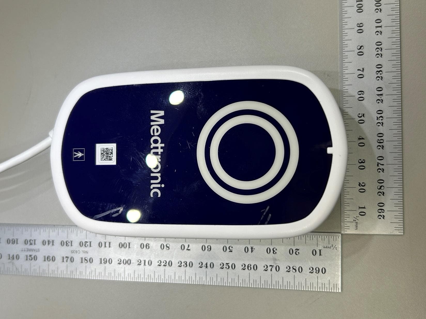
LF526950
Mar 27, 2026MyCareLink Home Communicator Model 26950
Equipment Class
DTS - Digital Transmission System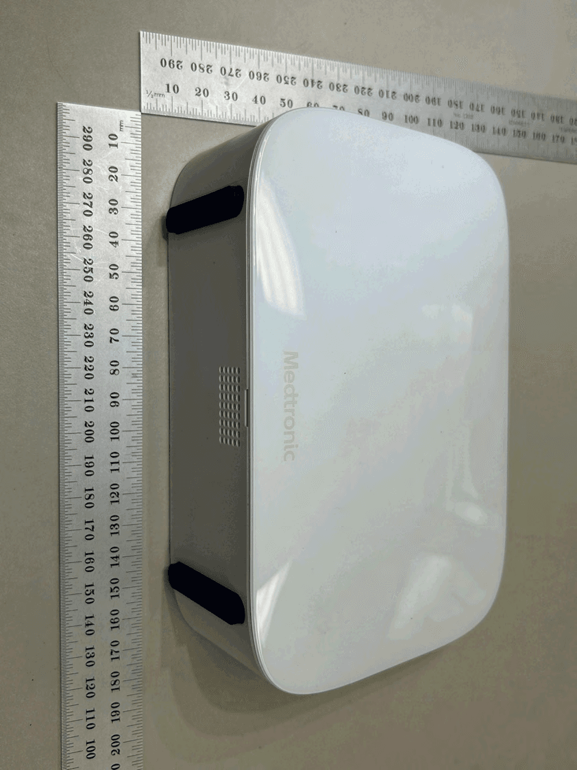
LF526900
Mar 27, 2026MyCareLink Home Communicator Model 26900
Equipment Class
DTS - Digital Transmission System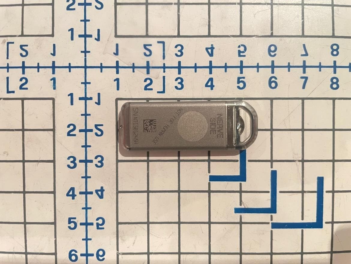
LF5P7850N
Sep 24, 2023Implantable Neurostimulator
Equipment Class
DCD - Part 15 Low Power Transmitter Below 1705 kHz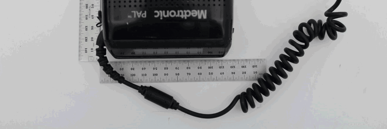
LF5MCS3101CO
May 14, 2020MCS3101CO
Equipment Class
DTS - Digital Transmission System