LF5MICSMEDICAL IMPLANT PROGRAMMER/CONTROL TRANSMITTER
Medtronic, Inc.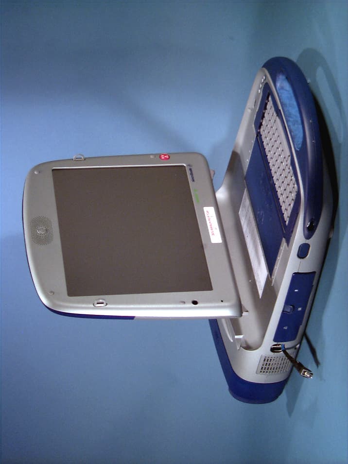
Click to zoom
Application Details
- Equipment Class
- TNB - Licensed Non-Broadcast Station Transmitter
- Date of Grant
- Nov 26, 2002
- Application Purpose
- Original Equipment
- Date of Application
- Oct 07, 2002
- Equipment Note
- MEDICAL IMPLANT PROGRAMMER/CONTROL TRANSMITTER
- Frequency Range
- 402.00000000 - 405.00000000
- Company
- Medtronic, Inc.
- Country
- United States
Documents & Files
Document Text
Text extracted from the exhibit documents filed with the FCC. Open a document above to read the original.
Users Manual
DOCUMENT TITLENUMBERREVPAGE Telemetry C Tech Brief - BC_Scenarios Appendix_Tel_BC DRAFT 1.0 1 MEDTRONIC CONFIDENTIALAppendix.doc modified 07/01/02 2:22 pm 1 2 3 4 5 6 7 8 9 10 11 12 13 14 15 16 17 18 19 20 21 22 23 24 25 26 27 28 29 30 31 32 33 34 35 36 37 38 39 40 41 42 43 44 45 46 47 48 49 50 51 52 53 54 55 56 57 58 59 60 61 62 63 64 65 66 1 2 3 4 5 6 7 8 9 10 11 12 13 14 15 16 17 18 19 20 21 22 23 24 25 26 27 28 29 30 31 32 33 34 35 36 37 38 39 40 41 42 43 44 45 46 47 48 49 50 51 52 53 54 55 56 57 58 59 60 61 62 63 64 65 66 Telemetry B/C Operations 1.0PURPOSE This section describes the operation of the Telemetry B/C systems as they coexist together in a product. 2.0DESCRIPTION In the Telemetry B/C usage model implant supports both telemetry systems (Telemetry B and Telemetry C). The Telemetry B is the primary system used for initiating communication before switching over to Telemetry C. A Programmer selects the telemetry system to use for bi-directional communication with the implant. Once the telemetry system is selected for communication then programmer transmits an open session request in the selected telemetry system. The activation mechanism is as follows: •Both telemetry systems are activated when a magnet presence is detected. Telemetry B start to beacon, while Telemetry C listens to establish bidirectional communication. The programmer does the Auto-id in Telemetry B, based on the uplink response. It selects the telemetry system for bidirectional communication and transmits an open session downlink in the selected telemetry system. Upon receipt of a valid open session downlink, the implant disables the “other” telemetry system (C in this example), and bidirectional communication session is estab- lished. Note: An implant with dual telemetry system will have a new sub-model id. DOCUMENT TITLENUMBERREVPAGE Telemetry C Tech Brief - BC_Scenarios Appendix_Tel_BC DRAFT 1.0 2 MEDTRONIC CONFIDENTIALAppendix.doc modified 07/01/02 2:22 pm 1 2 3 4 5 6 7 8 9 10 11 12 13 14 15 16 17 18 19 20 21 22 23 24 25 26 27 28 29 30 31 32 33 34 35 36 37 38 39 40 41 42 43 44 45 46 47 48 49 50 51 52 53 54 55 56 57 58 59 60 61 62 63 64 65 66 1 2 3 4 5 6 7 8 9 10 11 12 13 14 15 16 17 18 19 20 21 22 23 24 25 26 27 28 29 30 31 32 33 34 35 36 37 38 39 40 41 42 43 44 45 46 47 48 49 50 51 52 53 54 55 56 57 58 59 60 61 62 63 64 65 66 2.1SYSTEM DESCRIPTION/REQUIREMENTS: 2.1.1SESSION ESTABLISHMENT: A presence of magnet or a receipt of a valid device ID downlink activates both telemetry systems. The Telemetry B system to beacon and Telemetry C system to listen. The two user models for establishing a session with Telemetry B/C are as follows: 1) Desktop Application: The user can invoke an Auto-id from the desktop application software on the programmer. When an Auto-Id button is pressed - triggering the programmer to begin its search for the implant - as part of this search programmer transmits device id requests. The device id uplink response contains the implant’s unique sub-model id, based on the uplink response and if the 2090 programmer supports Telemetry C the device application software will select either the Telemetry B or C application to open a communication session with a selected implant. 2) Application software is selected prior to opening a session: If the application software which supports Telemetry C is already selected then user must swipe a magnet over the implant to activate the implant’s listen mode. The programmer will search for Telemetry C implant(s) with a specific model. A button press on the programmer will issue a device id request if one or more implant device(s) are found a user action will be required to select the appropriate implant after which an open request downlink request will be transmitted to establish the bi-directional communication session. DOCUMENT TITLENUMBERREVPAGE Telemetry C Tech Brief - BC_Scenarios Appendix_Tel_BC DRAFT 1.0 3 MEDTRONIC CONFIDENTIALAppendix.doc modified 07/01/02 2:22 pm 1 2 3 4 5 6 7 8 9 10 11 12 13 14 15 16 17 18 19 20 21 22 23 24 25 26 27 28 29 30 31 32 33 34 35 36 37 38 39 40 41 42 43 44 45 46 47 48 49 50 51 52 53 54 55 56 57 58 59 60 61 62 63 64 65 66 1 2 3 4 5 6 7 8 9 10 11 12 13 14 15 16 17 18 19 20 21 22 23 24 25 26 27 28 29 30 31 32 33 34 35 36 37 38 39 40 41 42 43 44 45 46 47 48 49 50 51 52 53 54 55 56 57 58 59 60 61 62 63 64 65 66 2.1.2HOLTER MONITOR: The Telemetry C specific holter monitor would be ideal to use with the Telemetry C system. The design of this unit is yet to be started and its development may not be completed for the first Telemetry C implant product. Meanwhile Telemetry B holter monitor could be used with the Telemetry B/C system. Their are two unique environments for the holter usage: Clinical environment: - where it is desireable to capture data using the holter monitor while in a programming session with a programmer. In this environment implant could be in session with the programmer while simultaneously transmitting data to the holter monitor unit. This allows for the analysis of the holter data at a later time. Non-Clinical environment: - in this environment implant is not required to maintain a communi- cation session with the programmer while simultaneously transmitting data to the holter monitor. Typically the implant is programmed to transmit the holter data for a period of time typically 24 to 48 hours and patient is given the holter monitor unit to record data for a period of time. Once the holter recording time expires either the patient sends the holter data to the clinic or patient comes to the clinic - during this holter data capture a programmer session is not open. 2.1.2.1TELEMETRY B/C HOLTER MONITOR OPERATIONS: The Telemetry B/C system is being designed to use Telemetry B holter monitor while using Telemetry C for a programmer-implant communication session. Telemetry B Holter Monitor usage with Telemetry C system: During a Telemetry C communciation session between a programmer-implant - When a clinican pro…
Text truncated - open the document above for the full version.
Users Manual
The following is a draft of the proposed wording for the statement required by 95.2115 that is to be included in the instruction manual for this device. This transmitter is authorized by rule under the Medical Implant Communications Service (47 C.F.R. Part 95) and must not cause harmful interference to stations operating in the 400.150 - 406.000 MHz band in the Meteorological Aids (i.e. transmitters and receivers used to communicate weather data), the Meteorological Satellite, or the Earth Exploration Satellite Services and must accept interference that may be caused by such aids, including interference that may cause undesired operation. This transmitter shall be used only in accordance with the FCC Rules governing the Medical Implant Communications Service. Analog and digital voice communications are prohibited. Although this transmitter has been approved by the Federal Communications Commission, there is no guarantee that it will not receive interference or that any particular transmission from this transmitter will be free from interference.
Cover Letter(s)
TRP INC. October 6, 2002 Federal Communications Commission 7435 Oakland Mills Rd Columbia, MD 21036 Re: Application for Grant of Certification for FCC ID: LF5MICS Gentlemen: Transmitted herewith is an application for certification of a device called a Carelink Programmer. The Carelink Programmer is a medical device that incorporates a Part 95 Subpart I compliant telemetry link for the purpose of telecommand and retrieval of stored patient data from an implanted device. Once the data is retrieved, it can be sent to the physician via the telephone line through an internal modem. Since the device is used for medical diagnostic test purposes, the digital electronics associated with it are exempt under the provisions of Section 15.103(c). This Programmer complies with the provisions of Part 95 for spectrum monitoring before transmitting. The unit incorporates a transceiver module (RFT)to provide the above functionality that operates under software control. Sincerely, Phillip Inglis Consultant to Medtronic 14085 Howard Rd Dayton, MD 21036
Cover Letter(s)
October 6, 2002 Federal Communications Commission 7435 Oakland Mills Rd Columbia, MD 21036 Re: Request for Confidentiality for FCC ID:LF5MICS Pursuant to Sections 0.457(d)(l)(ii) and 0.459 of the Commission’s Rules, Medtronic Incorporated (Applicant) hereby requests post grant confidential treatment of information accompanying their submission for certification as outlined below: - Schematics - Block Diagram - Technical Circuit Description The above materials contain trade secrets and proprietary information not customarily released to the public. The public disclosure of these matters would be harmful to the Applicant and provide unjustified benefits to its competitors. The Applicant understands that pursuant to Rule 0.457(d)(1)(ii), disclosure of the application and all information contained in the application for grant of certification for the above FCC ID will not be made before the date of the Grant for this Application. Sincerely, Phillip Inglis Consultant to Medtronic Inc. 14085 Howard Rd Dayton, MD 21036
External Photos
© 2002 PCTEST Lab FCC ID: LF5MICS NVLAP Lab Code: 100431-0 Medtronics Carelink Programmer © 2002 PCTEST Lab FCC ID: LF5MICS NVLAP Lab Code: 100431-0 Medtronics Carelink Programmer © 2002 PCTEST Lab FCC ID: LF5MICS NVLAP Lab Code: 100431-0 Medtronics Carelink Programmer © 2002 PCTEST Lab FCC ID: LF5MICS NVLAP Lab Code: 100431-0 Medtronics Carelink Programmer © 2002 PCTEST Lab FCC ID: LF5MICS NVLAP Lab Code: 100431-0 Medtronics Carelink Programmer
ID Label/Location Info
Proposed RFT Label. Label location to be on external surface on bottom of unit. Other material may be placed on the label as well. FCC ID:LF5MICS This device may not interfere with stations operating in the 400.150 -406.000 MHz band in the Meteorological Aids, Meteorological Satellite, and Earth Exploration Satellite Services and must accept any interference received, including interference that may cause undesired operation.
ID Label/Location Info
© 2002 PCTEST Lab FCC ID SAMPLE LABEL & LOCATION LABELLING REQUIREMENTS PER §§ 2.925 & 15.19(a)(3) The Label shown shall be permanently affixed at a conspicuous location on the device and be readily visible to the user at the time of purchase. SEE NEXT PAGE
RF Exposure Info
RF Exposure Statement: The Medtronic programmer/controller FCC ID:LF5MICS is defined by the FCC RF Exposure regulations as a mobile device. It is not intended to be operated with the integral antenna less than 20 cm from a human body. With an EIRP of 25 uWatts or less, it is incapable of generating RF fields that would exceed the requirements of Sections 2.1091 and 1.1310 of the FCC Rules. Phillip Inglis Consultant to Medtronic.
Test Report
© 2002 PCTEST Engineering Lab., Inc. 6660-B Dobbin Road • Columbia, MD 21045 • U.S.A. PCTEST Engineering Laboratory, Inc. TEL (410) 290-6652 • FAX (410) 290-6654 http://www.pctestlab.com CERTIFICATE OF COMPLIANCE FCC Part 95 Certification Medtronic, Inc. Dates of Tests: July 21, 2002 7000 Central Ave. Test Report S/N: 95.220719375.LF5 Minneapolis, MN 55432-3576 Test Site: PCTEST Lab, MD U.S.A. Attention: Mr. Len Twetan, Senior Product Development Manager FCC ID LF5MICS APPLICANT Medtronic, Inc. Classification: Licensed Non-Broadcast Transmitter Worn on the Body FCC Rule Part(s): §§§ 95 EUT Type: Carelink Programmer Trade Name(s): Medtronic Model(s): 2090 Tx/Rx Frequency Range: 402.15 — 404.85 MHz Max. RF Output Power: 21.6 μW Frequency Tolerance: 16 ppm Emission Designator: 46K0F1D Channel Capacity: 10 This equipment has been shown to be capable of compliance with the applicable technical standards as indicated in the measurement report and was tested in accordance with the measurement procedures specified in §2.947. I attest to the accuracy of data. All measurements reported herein were performed by me or were made under my supervision and are correct to the best of my knowledge and belief. I assume full responsibility for the completeness of these measurements and vouch for the qualifications of all persons taking them. PCTEST certifies that no party to this application has been denied the FCC benefits pursuant to Section 5301 of the Anti-Drug Abuse Act of 1988, 21 U.S.C. 862. 220719375.LF5 Certification TABLE OF CONTENTS ATTACHMENT A: COVER LETTER(S) ATTACHMENT B: ATTESTATION STATEMENT(S) ATTACHMENT C: TEST REPORT SCOPE 1 INTRODUCTION 2 INSERTS 3 DESCRIPTION OF TESTS 4-6 RADIATED MEASUREMENTS 7 FREQUENCY STABILITY 8-9 PLOTS OF EMISSIONS 10 LIST OF TEST EQUIPMENT 11 SAMPLE CALCULATIONS 12 CONCLUSION 13 ATTACHMENT D: TEST PLOTS ATTACHMENT E: FCC ID LABEL & LOCATION ATTACHMENT F: TEST SETUP PHOTOGRAPHS ATTACHMENT G: EUT PHOTOGRAPHS ATTACHMENT H: BLOCK DIAGRAM(S) ATTACHMENT I: SCHEMATIC DIAGRAM(S) ATTACHMENT J: USER’S MANUAL © 2002 PCTEST Engineering Laboratory, Inc. FCC Part 95 Test Report S/N: 95.220719375.LF5 FCC Part 95 Dates of Tests: July 21, 2002 Certification © 2002 PCTEST Lab FCC ID: LF5MICS 1 Medtronics Carelink Programmer MEASUREMENT REPORT 1.1 Scope Measurement and determination of electromagnetic emissions (EME) of radio frequency devices including intentional and/or unintentional radiators for compliance with the technical rules and regulations of the Federal Communications Commission. General Information Applicant Name: Medtronic, Inc. Address: 7000 Central Ave. Minneapolis, MN 55432-3576 Attention: Mr. Len Twetan, Senior Product Development Manager • FCC ID: LF5MICS • Model(s): 2090 • Quantity: Quantity production is planned • Tx/Rx Freq. Range: 402.15 — 404.85 MHz • Equipment Class: Licensed Non-Broadcast Transmitter Worn on the Body • Equipment Type: Carelink Programmer • Emission Designator: 46K0F1D • Modulation: FM • Frequency Tolerance: 16 ppm • Max. Power: 21.6 μW • FCC Rule Part(s): §§§§ 95 • Dates of Tests: July 21, 2002 • Place of Tests: PCTEST Lab, Columbia, MD U.S.A. • Test Report S/N: 95.220719375.LF5 Test Report S/N: 95.220719375.LF5 FCC Part 95 Dates of Tests: July 21, 2002 Certification 2.1 INTRODUCTION Figure 1. Map of the Greater Baltimore and Metropolitan Washington, D.C. area. These measurement tests were conducted at PCTEST Engineering Laboratory, Inc. facility in New Concept Business Park, Guilford Industrial Park, Columbia, Maryland. The site address is 6660-B Dobbin Road, Columbia, MD 21045. The test site is one of the highest points in the Columbia area with an elevation of 390 feet above mean sea level. The site coordinates are 39° 11'15" N latitude and 76° 49'38" W longitude. The facility is 1.5 miles North of the FCC laboratory, and the ambient signal and ambient signal strength are approximately equal to those of the FCC laboratory. There are no FM or TV transmitters within 15 miles of the site. The detailed description of the measurement facility was found to be in compliance with the requirements of § 2.948 according to ANSI C63.4 on October 19, 1992. Figure 2. 3-meter outdoor test site Measurement Procedure The radiated and spurious measurements were made outdoors at a 3-meter test range (see Figure2). The equipment under testing was placed on a wooden turntable, 3-meters from the receive antenna. The receive antenna height and turntable rotations was adjusted for the highest reading on the receive spectrum analyzer. A half-wave dipole was substituted in place of the EUT. This dipole antenna was driven by a signal generator and the level of the signal generator was adjusted to obtain the same receive spectrum analyzer reading. This level was recorded. For readings above 1 GHZ, the above procedure would be repeated using horn antennas and the difference between the gain of the horn and an isotropic antenna are taken into consideration. © 2002 PCTEST Lab FCC ID: LF5MICS 2 Medtronics Carelink Programmer Test Report S/N: 95.220719375.LF5 FCC Part 95 Dates of Tests: July 21, 2002 Certification 3.1 INSERTS Block Diagram(s) & Circuit Diagram(s) The block diagram is shown in Attachment I, and the circuit diagram is shown in Attachment J. Operating Instructions The instruction manual is shown in Attachment K. © 2002 PCTEST Lab FCC ID: LF5MICS 3 Medtronics Carelink Programmer Test Report S/N: 95.220719375.LF5 FCC Part 95 Dates of Tests: July 21, 2002 Certification 4.1 DESCRIPTION OF TESTS 4.2 Transmitter Audio Frequency Response N/A 4.3 Modulation Limiting N/A © 2002 PCTEST Lab FCC ID: LF5MICS 4 Medtronics Carelink Programmer Test Report S/N: 95.220719375.LF5 FCC Part 95 Dates of Tests: July 21, 2002 Certification 4.1 DESCRIPTION OF TESTS (CONTINUED) 4.4 20dB Bandwidth The unit was internally modulated and the Spectrum Analyzer was set with a Resolution Bandwidth of 100Hz and a Video Bandwidth of 100Hz. 4.5 Spurious and Harmonic Emissions at Antenna Te…
Text truncated - open the document above for the full version.
Test Report
Listen Before Talk Test Report Greg Haubrich Charles Dudding Phil Inglis Medtronic, Inc. 7000 Central Ave. N.E., T118 Minneapolis, MN 55432 PURPOSE: The purpose of this test report is to demonstrate the Listen Before Talk (LBT) operation of the Medical Implant Communications System (MICS) System that Medtronic has proposed to the MPT for including in their Radio Law. This system consists of a MICS Implant and a MICS Programmer/Controller that uses the LBT circuit to select the channel for communications based on the channel with the lowest ambient measured signal. The LBT operation of the programmer/controller was designed to comply with the protocol proposed by Medtronic to the MPT. This protocol has been adopted for these systems by the FCC and is nearing adoption in Europe by the European Telecommunications Standards Institute (ETSI). BACKGROUND: In reviewing the proposal for sharing the 401- 406 MHz band between the Meteorological Aids users and medical implant communications systems, the ITU-R SA 1346 study group concluded that interference between the two services must be reduced to the lowest possible level. It was their conclusion that medical implant communications systems should employ technology to avoid existing users of the band. By implementing a mechanism for interference avoidance, the medical implant communications systems would have little or no potential to interfere with the Meteorological Aids users, and the potential for interference between MICS users would also be lowered. The MICS programmer/controller contains the circuitry required to select the channel of operation of the system according to the LBT protocol. The protocol was designed to select a channel for operation with a very low potential for interfering with an existing user of the spectrum. The method of selecting this channel is to measure the existing ambient levels at the installation site and select the channel that meets the requirements of the protocol specification. TEST SET-UP: A series of signal generators were used to simulate existing ambient signals in a typical medical hospital environment. Each signal generator was used to represent an interfering ambient signal in one of the ten available channels in the 402 – 405 MHz band. The signals from these generators were combined and injected into the MICS monitoring system and its performance noted in a series of tests. Once the interfering signals were set up (amplitude and frequency of each signal) a data communications session was opened. For the first test, 5 generators were set to simulate ambient level signals ranging from –45 to –80 dBm as measured by the RSSI circuit in the programmer/controller. The programmer/controller was then instructed to start a MICS session and the frequency of the selected channel recorded. The recorded frequency was then compared to the frequencies of the interfering signal sources to insure the channel selected was the channel with the lowest measured ambient signal level. The next test added another signal generator in one of the remaining clear channels in order to show the LBT circuitry could successfully measure the additional signal in the band and select a new channel with the lowest ambient signal level. The MICS programmer/controller and implant system were connected via cabling to the signal generator interfering sources with a, fixed, signal path-loss of approximately 73 dB between the MICS Implant and the MICS Programmer Controller to enable normal two-way data communication of the system (see Figure 1). Seventy-three dB is the calculated path loss that will occur during typical physician patient programming sessions. Interfering “noise signals” were injected into the conducted RF path for the Programmer/Controller and the Implant RF Transceivers. The frequency, amplitude, and modulation characteristics of the interfering signal sources were set and the combined signal was injected into the RF Path (as shown in Figure 1). The Programmer/Controller was manually instructed, the process used by a physician, to open a communications session with the MICS Implanted device. The channel that the session originated on (and remained on) was the channel selected according to the LBT protocol. The test was repeated with different injected noise levels and patterns using additional signal generators as described below. TEST METHOD: The following test is designed to use direct connection of the interfering sources to the programmer/controller monitoring input circuits and the implant as shown in Figure 1. This test set-up allows the communications link to operate normally in the presence of the applied RF interference. The RF signal generators used as the interference sources were modulated with 24 kHz frequency deviation at a 1 kHz sinusoidal rate. This produces an occupied bandwidth for the interfering signals of 50 kHz. The center frequency of each RF generator is set to one of the center frequencies of each of the ten 300 kHz MICS channels from 402 MHz to 405 MHz. The level of each of the RF signal generators may be set independently to obtain the interfering signal level profiles as described below. The procedure that was previously shown to the MPT and accepted by them for showing the performance of the LBT circuitry is listed below. 1. Set a signal generator to a frequency within one of ten 300 kHz wide channels in the 402-405 MHz band. The signal should be FM modulated with a 1 kHz tone, 50 kHz occupied bandwidth, and have an output level between –30 and –80 dBm 2. Repeat the above until a total of five interfering signals are placed in separate channels within the 402-405 MHz band. Output levels from signal sources should range from –30 to –80 dBm. Spacing between signals should allow five 300 kHz wide channels with no interfering signals. 3. Activate the programmer/controller and scan the band. Read out the results of the scan from its memory and record the data as a chart of frequency versus amplitude.…
Text truncated - open the document above for the full version.
Test Setup Photos
© 2002 PCTEST Lab FCC ID: LF5MICS NVLAP Lab Code: 100431-0 Medtronics Carelink Programmer © 2002 PCTEST Lab FCC ID: LF5MICS NVLAP Lab Code: 100431-0 Medtronics Carelink Programmer © 2002 PCTEST Lab FCC ID: LF5MICS NVLAP Lab Code: 100431-0 Medtronics Carelink Programmer
Contact Information
Applicant
Guillaume Girard(Sr. RF Regulatory Program Manager)
Technical Contact
TRP IncPhillip Inglis
[email protected]410 531 3439
14085 Howard Rd · Dayton, Maryland · United States
Non-Technical Contact
TRP IncPhillip Inglis
[email protected]410 531 3439
Test Firm
PCTEST Engineering Laboratory, Inc.Randy Ortanez
Technical Specifications
| # | Rule Parts | Frequency Range | Power Output | Emission | Tolerance |
|---|---|---|---|---|---|
| 1 | 95I | 402 MHz - 405 MHz | 21.60 µW | 46K0F1D | 100.0000000000 ppm |
Other Applications from Medtronic, Inc.
LF5BLEIMPLANT5
Jul 09, 2026Confirma DR/SR MRI SureScan, Effectra DR/SR MRI SureScan, Refina CSP DR/SR MRI SureScan, Restoria CSP DR/SR MRI SureScan, ReSyncra CSP DR MRI SureScan, HarmoniaBP DR MRI SureScan
Equipment Class
DTS - Digital Transmission System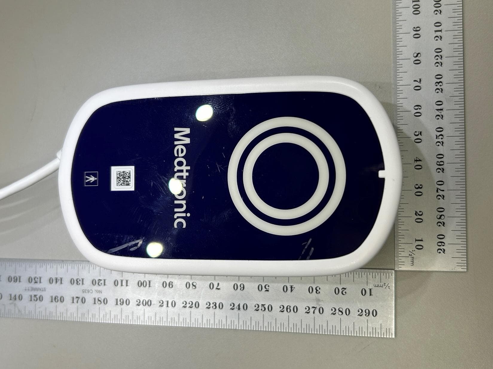
LF526950
Mar 27, 2026MyCareLink Home Communicator Model 26950
Equipment Class
DTS - Digital Transmission System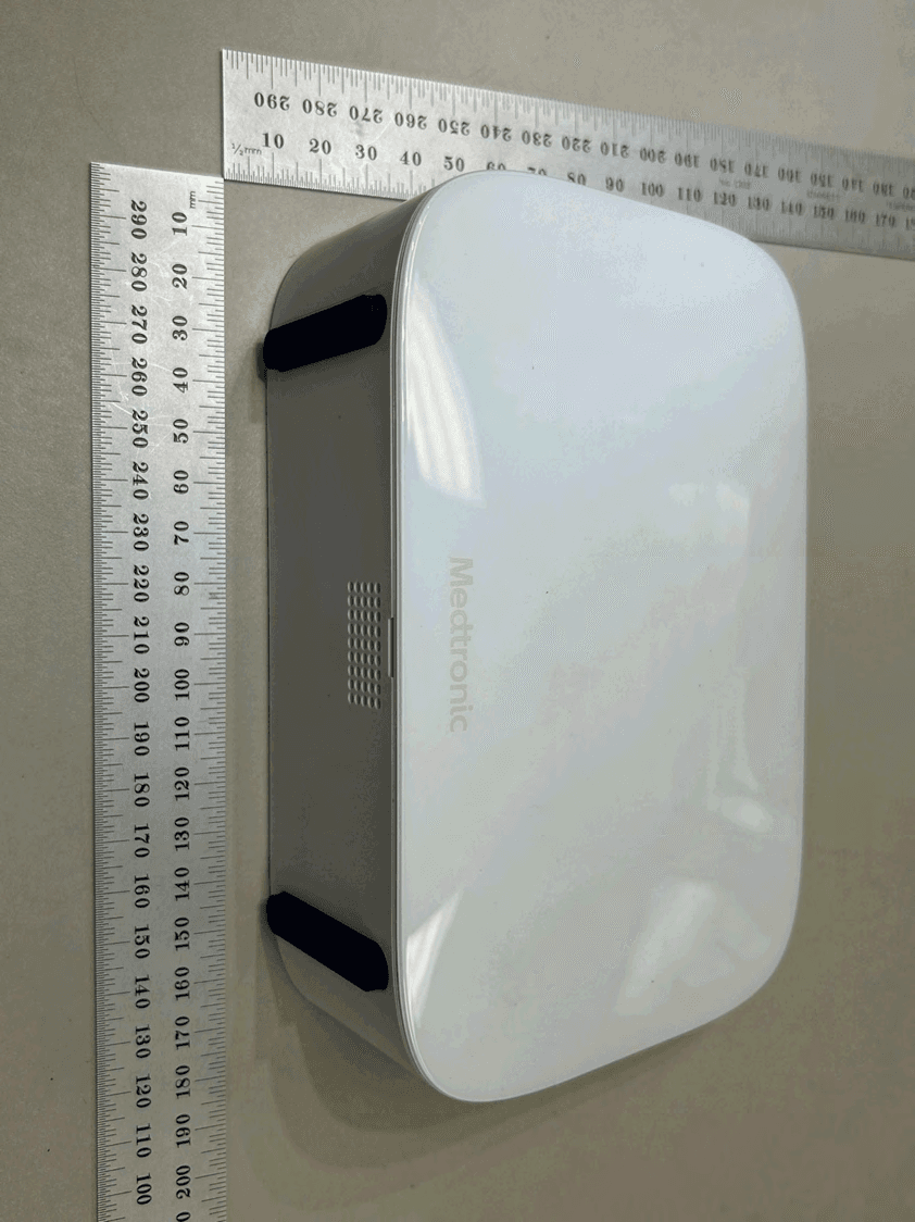
LF526900
Mar 27, 2026MyCareLink Home Communicator Model 26900
Equipment Class
DTS - Digital Transmission System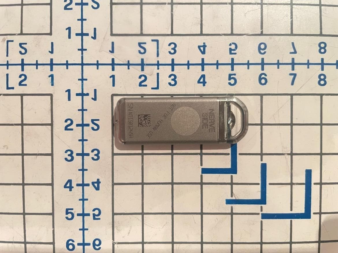
LF5P7850N
Sep 24, 2023Implantable Neurostimulator
Equipment Class
DCD - Part 15 Low Power Transmitter Below 1705 kHz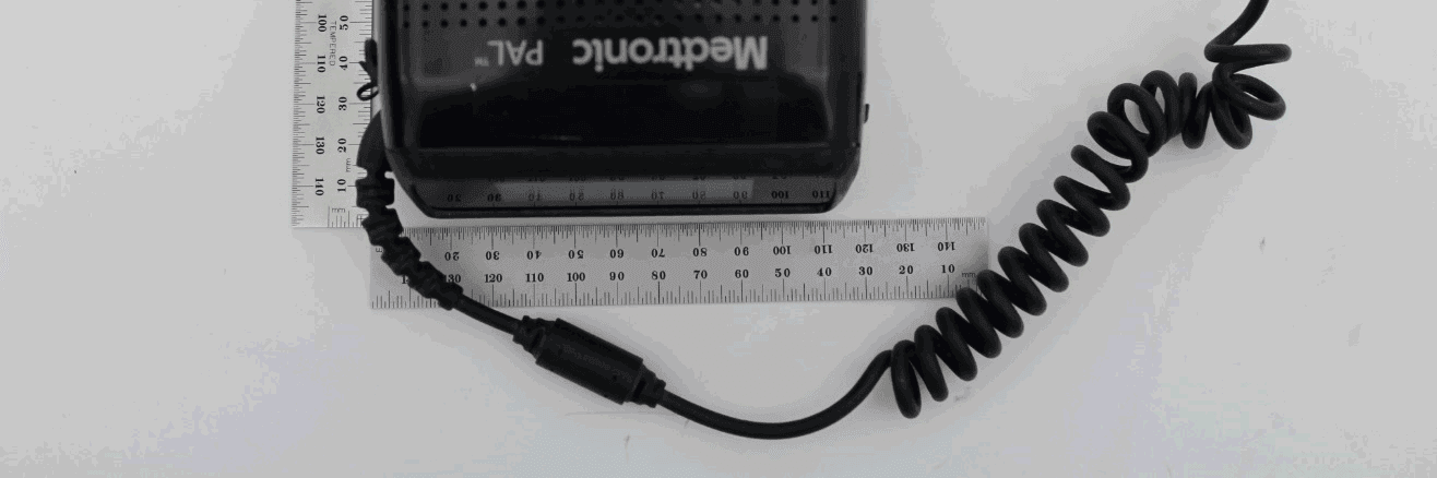
LF5MCS3101CO
May 14, 2020MCS3101CO
Equipment Class
DTS - Digital Transmission System