LG4T6210Occupancy Sensor
Smart Systems International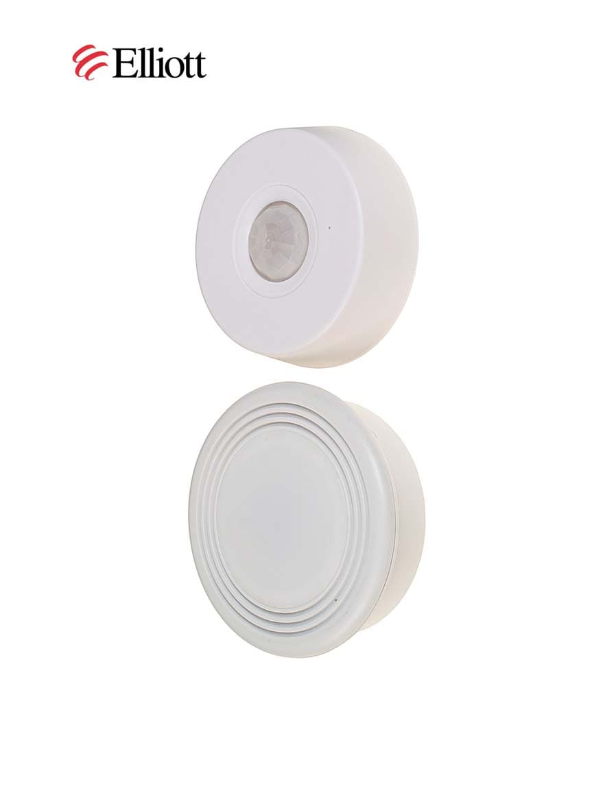
Click to zoom
Application Details
- Equipment Class
- DXT - Part 15 Low Power Transceiver, Rx Verified
- Date of Grant
- Nov 23, 2005
- Application Purpose
- Original Equipment
- Date of Application
- Nov 23, 2005
- Equipment Note
- Occupancy Sensor
- Frequency Range
- 915.03400000 - 915.03400000
- Company
- Smart Systems International
- Country
- United States
Documents & Files
Document Text
Text extracted from the exhibit documents filed with the FCC. Open a document above to read the original.
Users Manual
T6210 Motion Sensor Manual Operation Manual-T6210 Motion Sensor The T6210 motion sensor unit works in conjunction with the T6510 thermostat to enable total management of all the functions of the HVAC unit. Working together, they give you a greater measure of control over how your HVAC unit will operate in varying conditions. Install the unit by first removing the base. Grasp the base and twist it counter-clockwise. Use two screws to affix the base to the ceiling or the top of a wall that provides the unit with an unobstructed view of the area to be under motion sensing. Install four (4) AA batteries in the sensor unit. The proper orientation of the batteries is shown on symbols next to the battery holders. Placing the ridges on the base above the battery holders, slip the teeth of the motion sensor unit into the base, and rotate the base clockwise until it locks into place. T6210 Motion Sensor Manual Installation Considerations When installing the T6210 in a “Hard Wired configuration a Ferrite Bead (Fair-Rite 0431167281) or equivalent must be used. To install the bead, thread the cable from the AC unit through the bead, loop the cable around the bead once and thread it back through. Ensure that the bead is as close to the sensor as possible. This product has been tested and complies with the specifications for a Class B digital device, pursuant to Part 15 of the FCC Rules. These limits are designed to provide reasonable protection against harmful interference in a residential installation. This equipment generates, uses, and can radiate radio frequency energy and, if not installed and used according to the instructions, may cause harmful interference to radio communications. However, there is no guarantee that interference will not occur in a particular installation. If this equipment does cause harmful interference to radio or television reception, which is found by turning the equipment off and on, the user is encouraged to try to correct the interference by one or more of the following measures: Reorient or relocate the receiving antenna Increase the separation between the equipment or devices Connect the equipment to an outlet other than the receiver's Consult a dealer or an experienced radio/TV technician for assistance Smart Systems International 3271 S. Highland Drive Ste. 715 Las Vegas, NV 89109 This device complies with Part 15 of the FCC Rules. Operation is subject to the following two conditions: (1) this device may not cause interference, and (2) this device must accept any interference, including interference that may cause undesired operation of the device. Changes or modifications not expressly approved by Smart Systems International could void the user's authority to operate the equipment. This Class B digital apparatus complies with Canadian ICES- 003. Cet appareil numérique de la classe B est conforme à la norme NMB-003 du Canada.
Cover Letter(s)
September 2, 2005 American TCB 6731 Whittier Avenue, Suite C110 McLean, VA. 22101 Gentlemen: The enclosed documents constitute a formal submittal and application for a Grant of Equipment Authorization pursuant to Subpart C of Part 15 of FCC Rules (CFR 47) and Industry Canada RSS 210 regarding intentional radiators. Data within this report demonstrates that the equipment tested complies with the FCC limits for intentional radiators. Elliott Laboratories, as duly authorized agent prepared this submittal. A copy of the letter of our appointment as agent is enclosed. If there are any questions or if further information is needed, please contact Elliott Laboratories for assistance. Sincerely, Mark Briggs Principal Engineer MB/ Enclosures: Agent Authorization Letter Emissions Test Report with Exhibits
External Photos
External Photos
ID Label/Location Info
Label Placement T6210 Inside back Cover Smart Systems International 3271 S. Highland Drive Ste 715 Las Vegas, NV 89109 702-734-0044 www.2getsmart.com This device complies with Part 15 of the FCC Rules. Operation is subject to the following conditions: (1) this device may not cause harmful interference, and (2) this device must accept any interference received, including interference that may cause undesired operation. This Class A digital apparatus complies with Canadian ICES-003. Cet appareil numérique de la classe A est conforme à la norme NMB-003 du Canada. All Labels are Permanent and Self-Adhesive FCC ID: LG4T6210 Model T6210 Made in China IC ID:6211A-LG4T6210 FCC and IC Product Labels Product Interior Label 6210 FCC and IC Label Number 2 FCC ID: LG4T6210 Model T6210 Made in China IC ID:6211A-LG4T6210 Smart Systems International 3271 S. Highland Drive Ste 715 Las Vegas, NV 89109 702-734-0044 www.2getsmart.com 1" W 1 1/16" H This device complies with Part 15 of the FCC Rules. Operation is subject to the following conditions: (1) this device may not cause harmful interference, and (2) this device must accept any interference received, including interference that may cause undesired operation. This Class A digital apparatus complies with Canadian ICES-003. Cet appareil numérique de la classe A est conforme à la norme NMB-003 du Canada. 3 3/8" W ½" H
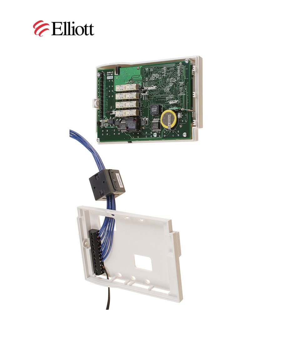
Internal Photos
Internal Photos
Test Report
File: R61048 Page 1 of 15 2016-01 Electromagnetic Emissions Test Report In Accordance With Industry Canada Radio Standards Specification 210 And FCC Part 15 Sections 15.249 on the Smart Systems International Transmitter Model: T6210 Occupancy Sensor UPN: 6211A-LG4T6210 FCC ID: LG4T6210 GRANTEE: Smart Systems International 3271 S. Highland Drive Las Vegas, NV 89109 TEST SITE: Elliott Laboratories, Inc. 684 W. Maude Avenue Sunnyvale, CA 94086 REPORT DATE: September 2, 2005 FINAL TEST DATE: July 12, July 28, July 29, August 3 and August 5, 2005 AUTHORIZED SIGNATORY: ______________________________ Mark Briggs Principal Engineer Elliott Laboratories, Inc. is accredited by the A2LA, certificate number 2016-01, to perform the test(s) listed in this report. This report shall not be reproduced, except in its entirety, without the written approval of Elliott Laboratories, Inc. Elliott Laboratories, Inc. -- EMC Department Test Report Report Date: September 2, 2005 File: R61048 Page 2 of 15 pages Equipment Name and Model: Transceiver , T6210 Occupancy Sensor Manufacturer: Smart Systems International 3271 S. Highland Drive Las Vegas, NV 89109 Tested to applicable standard: RSS-210, Issue 5, November 2001 (Low Power License-Exempt Radiocommunication Devices) FCC Part 15.249 Test Report Prepared For: Robert Zirpoli Smart Systems International 3271 S. Highland Drive Las Vegas, NV 89109 Measurement Facility Description Filed With Department of Industry: Departmental Acknowledgement Number: IC2845 SV1 Dated August 16, 2007 Declaration of Compliance I declare that the testing was performed or supervised by me; that the test measurements were made in accordance with the above mentioned departmental standards (through the use of ANSI C63.4: 2003 as referenced by FCC Part 15 and RSS-212, “Test Facilities and Test Methods for Radio Equipment” as referenced by section 4 of RSS-Gen Issue 1); and that the equipment performed in accordance with the data submitted in this report. Signature ______________________________ Name Mark Briggs Title Principal Engineer Elliott Laboratories Inc. Address 684 W. Maude Ave Sunnyvale, CA 94086 USA Date: September 2, 2005 Elliott Laboratories, Inc. -- EMC Department Test Report Report Date: September 2, 2005 File: R61048 Page 3 of 15 pages TABLE OF CONTENTS COVER PAGE..................................................................................................................................................................................1 TABLE OF CONTENTS...............................................................................................................................................................3 SCOPE.............................................................................................................................................................................................4 OBJECTIVE...................................................................................................................................................................................4 STATEMENT OF COMPLIANCE..............................................................................................................................................5 TEST RESULTS SUMMARY......................................................................................................................................................5 DEVICES OPERATING IN THE 902 – 928 / 2400 – 2483.5 / 5725 – 5850 MHZ BANDS................................................5 GENERAL REQUIREMENTS APPLICABLE TO ALL BANDS.........................................................................................5 MEASUREMENT UNCERTAINTIES.........................................................................................................................................6 EQUIPMENT UNDER TEST (EUT) DETAILS..........................................................................................................................7 GENERAL...................................................................................................................................................................................7 OTHER EUT DETAILS............................................................................................................................................................7 ENCLOSURE..............................................................................................................................................................................7 SUPPORT EQUIPMENT..........................................................................................................................................................7 EXTERNAL I/O CABLING......................................................................................................................................................7 EUT OPERATION.....................................................................................................................................................................7 TEST SITE......................................................................................................................................................................................8 GENERAL INFORMATION....................................................................................................................................................8 CONDUCTED EMISSIONS CONSIDERATIONS................................................................................................................8 RADIATED EMISSIONS CONSIDERATIONS....................................................................................................................8 MEASUREMENT INSTRUMENTATION..................................................................................................................................9 RECEIVER SYSTEM...............................................................................................................…
Text truncated - open the document above for the full version.
Test Setup Photos
Radiated Emissions Test Configuration Photograph Sensor and Remote Wired Radiated Emissions Test Configuration Photograph Sensor and Remote Wired Radiated Emissions Test Configuration Photograph Sensor Wireless Radiated Emissions Test Configuration Photograph Sensor Wireless Conducted Emissions Test Configuration Photograph Sensor and remote CE Conducted Emissions Test Configuration Photograph Sensor and remote CE
Contact Information
Applicant
Marc H Popek(V.P., Engineering)
Technical Contact
Elliott Laboratories, Inc.Mark Briggs
[email protected]408-245-7800
684 West Maude Ave · Sunnyvale, California · United States
Test Firm
Elliott Laboratories LLCDavid Bare
Technical Specifications
| # | Rule Parts | Frequency Range | Power Output |
|---|---|---|---|
| 1 | 15C | 915.034 MHz - 915.034 MHz | - |
Other Applications from Smart Systems International
LG4T6510
Nov 23, 2005Occupancy Sensor
Equipment Class
DXT - Part 15 Low Power Transceiver, Rx VerifiedLG4PST6000
Mar 04, 1997JBP - Part 15 Class B Computing Device Peripheral
Equipment Class
JBP - Part 15 Class B Computing Device PeripheralLG4PST5000
Sep 29, 1996Wireless Thermostat Transceiver
Equipment Class
DXX - Part 15 Low Power Communication Device TransmitterLG4PST3000
Jul 06, 1995CYY - Communications Receiver used w/Pt 15 Transmitter
Equipment Class
CYY - Communications Receiver used w/Pt 15 TransmitterLG4PST1000
Jun 15, 1994CYY - Communications Receiver used w/Pt 15 Transmitter
Equipment Class
CYY - Communications Receiver used w/Pt 15 Transmitter