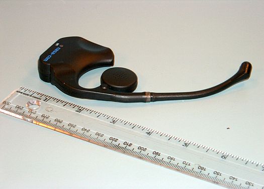
LLP9011Wireless Magnetic Headset MAH9011
NASACO Electronics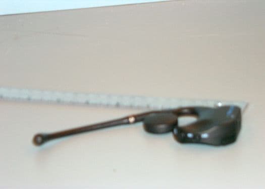
Click to zoom
Application Details
- Equipment Class
- DXX - Part 15 Low Power Communication Device Transmitter
- Date of Grant
- Nov 02, 2000
- Application Purpose
- Original Equipment
- Date of Application
- Nov 02, 2000
- Equipment Note
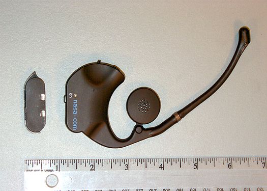
- Wireless Magnetic Headset MAH9011
- Frequency Range
- 0.40000000 - 0.41500000
- Company
- NASACO Electronics
- Country
- Hong Kong
Documents & Files
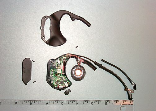
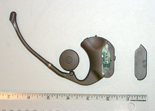
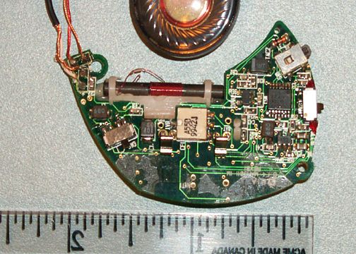
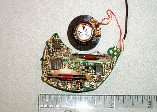
Document Text
Text extracted from the exhibit documents filed with the FCC. Open a document above to read the original.
Users Manual
http://www.nasa-com.com Page 1 of 7 - A Short Range Magnetic Inductive Technology - MG9030 includes the following Components: A) Wireless Headset Unit / with Ni-MH Rechargeable Battery Pack (Fig.1 & Fig.2) Fig.1 Fig.2 http://www.nasa-com.com Page 2 of 7 B) Base Unit / with Ni-MH Rechargeable Battery Pack (Fig.3 & Fig.4) POWER INDICATOR ON OFF Fig.3 Fig.4 C) Battery charger / with a AC to DC adaptor Fig. 5 Fig. 6 Fig. 7 http://www.nasa-com.com Page 3 of 7 How to use: Step 1) Insert the Battery Pack into the Base Unit to power it up. Step 2) Connect Base Unit to the audio receptacle on your cellular phone by the cable of the Base Unit. Adapter may be required for the connection. Consult your local distributor the suitable adapter for your phone. Step 3) Set your cellular phone to “auto receive” mode (provided that your cellular phone has this feature) if you want to be totally hand free. Step 4) Turn on the headset by the power switch as shown. ON POWER INDICATOR http://www.nasa-com.com Page 4 of 7 Step 5) Open the gap between the ear ride and the speaker and put the headset on your ear. (This headset is designed for both left and right ears) Step 6) Tighten the headset by moving the speaker back to the ear ride. Rotate the microphone tip to make it as closer to your month as possible. Step 7) Make a test call to a friend using your cellular phone. Dial tone should present if the key tone has been activated on your cellular phone. Step 8) Adjust the speaker volume by pushing the four-step volume button to achieve the appropriate speaker volume. (You may need to adjust the volume again if the Headset has been switched off) http://www.nasa-com.com Page 5 of 7 Troubleshooting: If you do not hear a dial tone when you try to make a phone call. 1. Make sure your Battery Pack is fully charged and inserted in your Headset and Base Unit. 2. Confirm the Power Switches on both Base Unit and Headset are on the ON position. 3. Be sure that the green LEDs is ON for both Base Unit and Headset when you push the keypad. 4. Make sure that the cable is compatible with your cellular phones. For most of the cellular phones, ”Headset" will display on the screen if the cable is connected correctly. 5. Confirm the volume of your cellular phone is set to the maximum level. 6. Try pushing the volume button on the headset to increase the audio level. Battery Charging: Step 1) Plug the AC to DC adaptor into the electric socket. Then connect the adaptor to the Battery Charger shown in Fig. 7. Step 2) Insert the battery pack into the Charger (Fig.6). Three battery packs can be charged at the same time independently. Step 3) The red LED on the Charger will be ON (Fig. 6) when the battery is being charged. Step 4) After approximate 10 hours, the battery pack will be fully charged and the red LED will be OFF. Step 5) Remove the battery pack from the Charger and insert it to the Base Unit or Headset for battery replacement. The charged battery will last for around 2.5 hours talk time or 150 hours in standby mode. It is recommended to put the discharged battery packs into the charger for overnight charging. http://www.nasa-com.com Page 6 of 7 Important Note: 1) Effective Transmission Distance is about 1.5 Meters (~ 5 feet). If you exceed this distance, the Headset will mute the speaker output. If you stay out of range for more than 32 seconds, the headset will automatically switch to standby mode to save battery life. At that time, the LED on the headset will be blinking and the red LED on the Base Unit will be on, indicating the link is broken. To establish the link, simply move Headset closer the Base Unit and both green LEDs on the Base Unit and the Headset will be ON again. 2) When the Base Unit is off or in standby mode, the headset will also automatically switch to standby after 32 seconds. 3) Make sure no obstacle between the Base Unit and Headset to receive optimal sound quality. 4) Only need to turn off the Base Unit and Headset when you do not want to use your cellular phone for a long time. 5) Do not attempt to put on your Headset or change the battery while driving. 6) While the mobile phone network signal strength is very weak, your mobile phone radiation power will automatically increase, resulting in some “mosquito” noise at your headset. When this happens, try moving the mobile phone further away from the Base Unit or changing the orientation of your mobile phone to minimize the noise. 7) You may experience some interference from other electronic equipment (such as computer monitor). In this case, you can change the frequencies of the Base Unit and the Headset by the hidden switches as indicated below from channel 1 to 2 (or vise versa). Make sure that both switches are at the positions of same channel. If this does not help, try moving the Base Unit away from the equipment. CH 2 CH 1 CH 2CH 1 http://www.nasa-com.com Page 7 of 7 These devices comply with part 15 of the FCC rules. Operation is subjected to the following two conditions: 1) This device may not cause harmful interference and 2) This device must accept any interference received, including interference that may cause undesired operation. Changes or modifications not expressly approved by the party responsible for compliance could void the users authority to operate the equipment.
Block Diagram
AUDIO LINE INPUT HEADSET RESONANT CIRCUIT 455 KHZ BANDPASS FILTER AUDIO LINE OUTPUT RECEIVED SIGNAL: CHB=403KHZ, CH C =413KHZ ANTENNA COIL ANTENNA COILS RESONANT CIRCUIT MODULATOR BASE RESONANT CIRCUIT SPEAKER 455 KHZ BANDPASS FILTER TRANSMITTED SIGNAL: CHB=1.762MHZ, CH C =1.784MHZ LO: CHB=455.5KHZ, CHC=454.6KHZ LO: CHB,CH C = 455.1KHZ RESONANT CIRCUIT LO: CHB=858KHZ, CHC=868KHZ MODULATOR TRANSMITTED SIGNAL: CHB=403KHZ, CH C =413KHZ MICROPHONE LO: CHB=2.2MHZ, CHC=2.23MHZ ANTENNA COILS RECEIVED SIGNAL: CHB=1.762MHZ, CH C =1.784MHZ
Cover Letter(s)
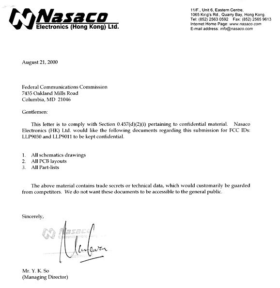
Response to Non-Conformities (Ref # E00-000497-1; FCC ID: LLP9011) Item 1: Please provide a brief description of the circuit functions of the device along with a statement describing how the device operates. 10/27 – Receive operational description Item 2: It appears two copies of the report were provided in one pdf file. Please explain and update if needed. 10/27 – Received revised test report. Previous test report had duplicate information. Item 3: I note that the FCC ID number is located on the battery compartment cover. There is a long standing Commission policy that prohibits the FCC ID label from being located on a battery compartment cover. These covers are frequently lost or misplaced and the consumer merely tapes the battery into place and continues to use the transmitter. Without the FCC ID label there is no way to determine who is responsible for compliance of the transmitter should a problem arise. 10/27 – Customer Label Justification The reason why the labels are in the battery compartment is that the size of the headset label is too large to place on the outside of the unit and in order to have consistent design with the heaset label, we decided to place the base label also in the battery compartment. Another reason is for better outlook if the label is in the battery compartment (just like with most of cellular phones). Item 4: The FCC ID number needs to be placed on its own line or enclosed within a box. Please resubmit a new label. 10/27 – Received revised label
ID Label/Location Info
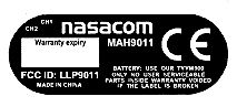
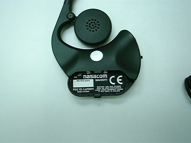
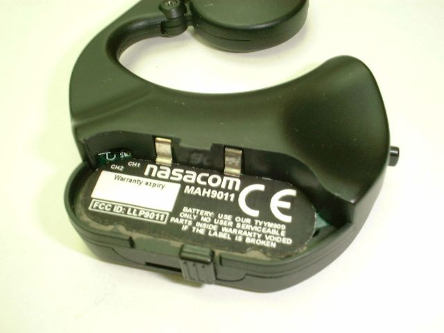
Customer Label Justification The reason why the labels are in the battery compartment is that the size of the headset label is too large to place on the outside of the unit and in order to have consistent design with the heaset label, we decided to place the base label also in the battery compartment. Another reason is for better outlook if the label is in the battery compartment (just like with most of cellular phones).
ID Label/Location Info
36.0 mm 20.0 mm R1.0 mm typ. 2 R6.5 mm typ. 2 13.0 mm MADE IN CHINA FCC ID: LLP9011 CH2 CH1 MAH9011 BATTERY: USE OUR TYYM900 ONLY NO USER SERVICEABLE PARTS INSIDE WARRANTY VOIDED IF THE LABEL IS BROKEN Warranty expiry 36.0 mm 15.5 mm R6.5mm typ.2 6.0 mm 13.0 mm 7.2 mm MADE IN CHINA CH2 CH1 MAB9030 BATTERY: USE OUR TYYM900 ONLY NO USER SERVICEABLE PARTS INSIDE WARRANTY VOIDED IF THE LABEL IS BROKEN Warranty expiry FCC ID: LLP9030
Operational Description
Headset: For the receiving parts, the antenna coil receives the signal (1.762MHz / 1.784MHz) from the base. The received signal is then mixed with the LO (2.2MHz / 2.23MHz) and pass through a 455kHz band-pass filter. The resulting signal from the filter will mixed with the second LO (455.1kHz) to give the voice signal. The voice signal will be amplified and output to the speaker. For the transmitting parts, the electrical signal from the microphone will be amplitude-modulated and up-converted to 403kHz/413kHz in the modulator. The RF signal will then be transmitted out by the resonant circuit.
Operational Description
Prepared By: Eric Wu Date: July 27, 2000 1 MG9030 Product Specification MAB9030 + MAH9011 Base MAB9030 Specification Transmission Frequency: Channel 1 – 1.762 MHz ± 2kHz Channel 2 – 1.784 MHz ± 2kHz Receiving Frequency: Channel 1 – 403.0 kHz ± 10kHz Channel 2 – 413.7 kHz ± 10kHz Audio Frequency Response: 300 Hz to 6kHz AM Modulation depth: ≦ 150% Fundamental radiation emission level measured @ 30m: < 10μV Operating Voltage: 3.2V to 4.5V Operating Range: ≧ 1.5 meter Operating Temperature: 0 ° °° ° C to 45 ° °° ° C Features Selectable channels Automatic power On/Standby 3.6V (40mAh) dedicated rechargeable battery pack Battery Talk time ≧ 2.5 hours Battery Standby time ≧ 150 hours Light weight 39g (included belt clip and battery) Red LED Power On Indication Green LED In Range Indication Integrated antennas 2.5mm stereo plug (compatible with most of the mobile phones by adding connectors) Controls Power On/Off switch Channel Selection switch LED indicators for Power On and In Range Prepared By: Eric Wu Date: July 27, 2000 2 Headset MAH9011 Specification Transmission Frequency: Channel 1 – 403.046 kHz ± 1kHz Channel 2 – 413.696 kHz ± 1kHz Receiving Frequency: Channel 1 – 1.762 MHz ± 10kHz Channel 2 – 1.784 MHz ± 10kHz Audio Frequency Response: 300 Hz to 6kHz AM Modulation depth: ≦ 120% Fundamental radiation emission level measured @ 30 meter: < 10μV Audio distortion: Nominal 5% Signal to Noise Ratio @ 1 meter: ≧ 40 dB Operating Voltage: 3.2V to 4.5V Operating Range: ≧ 1.5 meter Operating Temperature: 0 ° °° ° C to 45 ° °° ° C Features Selectable channels Automatic power On/Standby 3.6V (40mAh) dedicated rechargeable battery Battery Talk time ≧ 2.5 hours Battery Standby time ≧ 150 hours Light weight 26g (included battery) Blinking Green LED Standby Indication Green LED In Range Indication Integrated antennas Symmetrical design: suitable for wearing on either left or right ears 4-level audio output Low-Battery Sound Alert Noise cancellation Microphone Controls Power On/Off switch Channel Selection switch Volume control button LED indicator for Power On Prepared By: Eric Wu Date: July 27, 2000 3 Accessory 6Vdc 100mA UL listed (or CE/TUV) AC adapter Charging unit with 3 charging cavities 3 pieces of dedicated battery packs
Test Report
Page 1 of 24 Report No: FC00-081 NASACO ELECTRONICS TEST REPORT FOR THE WIRELESS MAGNETIC HEADSET, MAH9011 FCC PART 15 SUBPART B CLASS B & FCC PART 15 SUBPART C SECTION 15.209 COMPLIANCE DATE OF ISSUE: AUGUST 22, 2000 PREPARED FOR: Nasaco Electronics 11/F, Unit 6, Eastern Centre 1065 King's Road Quarry Bay, Hong Kong W.O. No: 74898 PREPARED BY: Joyce Walker CKC Laboratories, Inc. 5473A Clouds Rest Mariposa, CA 95338 Date of test: August 9-10, 2000 Report No: FC00-081 DOCUMENTATION CONTROL: _____________________________ Tracy Phillips Documentation Control Supervisor CKC Laboratories, Inc. APPROVED BY: _____________________________ Dennis Ward Director of Laboratories CKC Laboratories, Inc. This report contains a total of 24 pages and may be reproduced in full only. Partial reproduction may only be done with the written consent of CKC Laboratories, Inc. Page 2 of 24 Report No: FC00-081 TABLE OF CONTENTS Administrative Information ............................................................................................. 3 Summary Of Results........................................................................................................ 4 Equipment Under Test (EUT) Description...................................................................... 4 Measurement Uncertainty................................................................................................ 4 EUT Operating Frequency............................................................................................... 4 Peripheral Devices ........................................................................................................... 5 Report Of Measurements................................................................................................. 6 Table 1: Transmitter Fundamental Radiated Emission Levels........................... 6 Table 2: Transmitter Six Highest Radiated Emission Levels............................. 8 Table 3: Receiver Six Highest Radiated Emission Levels ................................. 9 Table A : List Of Test Equipment ................................................................................... 10 EUT Setup .......................................................................................................................10 Test Instrumentation And Analyzer Settings................................................................... 10 Table B : Analyzer Bandwidth Settings Per Frequency Range........................... 10 Spectrum Analyzer Detector Functions............................................................... 11 Peak ......................................................................................................... 11 Quasi-Peak............................................................................................... 11 Average.................................................................................................... 11 Test Methods ................................................................................................................... 11 Radiated Emissions Testing................................................................................. 12 Sample Calculations ........................................................................................................ 13 Appendix A : Information About The Equipment Under Test........................................ 14 I/O Ports............................................................................................................... 15 Crystal Oscillators ............................................................................................... 15 Printed Circuit Boards ......................................................................................... 15 Required EUT Changes To Comply.................................................................... 15 Photograph Showing Radiated Emissions ........................................................... 16 Photograph Showing Radiated Emissions ........................................................... 17 Photograph Showing Radiated Emissions ........................................................... 18 Photograph Showing Radiated Emissions ........................................................... 19 Appendix B : Measurement Data Sheets ......................................................................... 20 Page 3 of 24 Report No: FC00-081 CKC Laboratories, Inc. has Certificates of Accreditation from the following agencies: DATech (Germany); A2LA (USA); FCC (USA); VCCI (Japan); BSMI (Taiwan); HOKLAS (Hong Kong). CKC Laboratories, Inc. has Letters of Acceptance through an MRA for the following agencies: ACA/NATA (Australia); SABS (South Africa); SWEDAC (Sweden); TUV Rheinland-Germany; TUV Rheinland- Korea; TUV Rheinland-Russia; Radio Communications Agency (RA); NEMKO (Norway). ADMINISTRATIVE INFORMATION DATE OF TEST: August 9-10, 2000 PURPOSE OF TEST: To demonstrate the compliance of the Wireless Magnetic Headset, MAH9011, with the requirements for FCC Part 15 Subpart B Class B and FCC Part 15 Subpart C Section 15.209 devices. MANUFACTURER: Nasaco Electronics 11/F, Unit 6, Eastern Centre 1065 King's Road Quarry Bay, Hong Kong REPRESENTATIVE: Y.K. So TEST LOCATION: CKC Laboratories, Inc. 22105 Wilson River Hwy, Tillamook, OR 97141 5289 NE Elam Young Pkwy, Hillsboro, OR 97124 TEST PERSONNEL: Mike Wilkinson TEST METHOD: ANSI C63.4 1992 FREQUENCY RANGE TESTED: 9kHz - 1000 MHz EQUIPMENT UNDER TEST:Wireless Magnetic Headset Manuf:Nasaco Electronics Model:MAH9011 Serial:N/A FCC ID:LLP-9011 (pending) Page 4 of 24 Report No: FC00-081 SUMMARY OF RESULTS The Nasaco Electronics Wireless Magnetic Headset, MAH9011, was tested in accordance with ANSI C63.4 1992 for compliance with FCC Part 15 Subpart B Class B and FCC Part 15 Subpart C Section 15.209. As received, the above equipment was found to be fully compliant with the limits of FCC Part 15 Subpart B Class B and FCC Part 15 Subpart C Section 15.209. The results …
Text truncated - open the document above for the full version.
Test Setup Photos
Page 1 of 24 Report No: FC00-081 NASACO ELECTRONICS TEST REPORT FOR THE WIRELESS MAGNETIC HEADSET, MAH9011 FCC PART 15 SUBPART B CLASS B & FCC PART 15 SUBPART C SECTION 15.209 COMPLIANCE DATE OF ISSUE: AUGUST 22, 2000 PREPARED FOR: Nasaco Electronics 11/F, Unit 6, Eastern Centre 1065 King's Road Quarry Bay, Hong Kong W.O. No: 74898 PREPARED BY: Joyce Walker CKC Laboratories, Inc. 5473A Clouds Rest Mariposa, CA 95338 Date of test: August 9-10, 2000 Report No: FC00-081 DOCUMENTATION CONTROL: _____________________________ Tracy Phillips Documentation Control Supervisor CKC Laboratories, Inc. APPROVED BY: _____________________________ Dennis Ward Director of Laboratories CKC Laboratories, Inc. This report contains a total of 24 pages and may be reproduced in full only. Partial reproduction may only be done with the written consent of CKC Laboratories, Inc. Page 2 of 24 Report No: FC00-081 TABLE OF CONTENTS Administrative Information ............................................................................................. 3 Summary Of Results........................................................................................................ 4 Equipment Under Test (EUT) Description...................................................................... 4 Measurement Uncertainty................................................................................................ 4 EUT Operating Frequency............................................................................................... 4 Peripheral Devices ........................................................................................................... 5 Report Of Measurements................................................................................................. 6 Table 1: Transmitter Fundamental Radiated Emission Levels........................... 6 Table 2: Transmitter Six Highest Radiated Emission Levels............................. 8 Table 3: Receiver Six Highest Radiated Emission Levels ................................. 9 Table A : List Of Test Equipment ................................................................................... 10 EUT Setup .......................................................................................................................10 Test Instrumentation And Analyzer Settings................................................................... 10 Table B : Analyzer Bandwidth Settings Per Frequency Range........................... 10 Spectrum Analyzer Detector Functions............................................................... 11 Peak ......................................................................................................... 11 Quasi-Peak............................................................................................... 11 Average.................................................................................................... 11 Test Methods ................................................................................................................... 11 Radiated Emissions Testing................................................................................. 12 Sample Calculations ........................................................................................................ 13 Appendix A : Information About The Equipment Under Test........................................ 14 I/O Ports............................................................................................................... 15 Crystal Oscillators ............................................................................................... 15 Printed Circuit Boards ......................................................................................... 15 Required EUT Changes To Comply.................................................................... 15 Photograph Showing Radiated Emissions ........................................................... 16 Photograph Showing Radiated Emissions ........................................................... 17 Photograph Showing Radiated Emissions ........................................................... 18 Photograph Showing Radiated Emissions ........................................................... 19 Appendix B : Measurement Data Sheets ......................................................................... 20 Page 3 of 24 Report No: FC00-081 CKC Laboratories, Inc. has Certificates of Accreditation from the following agencies: DATech (Germany); A2LA (USA); FCC (USA); VCCI (Japan); BSMI (Taiwan); HOKLAS (Hong Kong). CKC Laboratories, Inc. has Letters of Acceptance through an MRA for the following agencies: ACA/NATA (Australia); SABS (South Africa); SWEDAC (Sweden); TUV Rheinland-Germany; TUV Rheinland- Korea; TUV Rheinland-Russia; Radio Communications Agency (RA); NEMKO (Norway). ADMINISTRATIVE INFORMATION DATE OF TEST: August 9-10, 2000 PURPOSE OF TEST: To demonstrate the compliance of the Wireless Magnetic Headset, MAH9011, with the requirements for FCC Part 15 Subpart B Class B and FCC Part 15 Subpart C Section 15.209 devices. MANUFACTURER: Nasaco Electronics 11/F, Unit 6, Eastern Centre 1065 King's Road Quarry Bay, Hong Kong REPRESENTATIVE: Y.K. So TEST LOCATION: CKC Laboratories, Inc. 22105 Wilson River Hwy, Tillamook, OR 97141 5289 NE Elam Young Pkwy, Hillsboro, OR 97124 TEST PERSONNEL: Mike Wilkinson TEST METHOD: ANSI C63.4 1992 FREQUENCY RANGE TESTED: 9kHz - 1000 MHz EQUIPMENT UNDER TEST:Wireless Magnetic Headset Manuf:Nasaco Electronics Model:MAH9011 Serial:N/A FCC ID:LLP-9011 (pending) Page 4 of 24 Report No: FC00-081 SUMMARY OF RESULTS The Nasaco Electronics Wireless Magnetic Headset, MAH9011, was tested in accordance with ANSI C63.4 1992 for compliance with FCC Part 15 Subpart B Class B and FCC Part 15 Subpart C Section 15.209. As received, the above equipment was found to be fully compliant with the limits of FCC Part 15 Subpart B Class B and FCC Part 15 Subpart C Section 15.209. The results …
Text truncated - open the document above for the full version.
Contact Information
Applicant
So Yan Kwan(Managing Director)
Technical Contact
CKC Laboratories, Inc.Tracy Phillips
[email protected]800 500 4362
5473A Clouds Rest · Mariposa, California · United States
Non-Technical Contact
CKC Laboratories, Inc.Joyce Walker
[email protected]800 500 4362
Test Firm
CKC Laboratories, Inc.Steve Behm
Technical Specifications
| # | Rule Parts | Frequency Range | Power Output |
|---|---|---|---|
| 1 | 15C | 0.4 MHz - 0.415 MHz | - |
Other Applications from NASACO Electronics

LLP-MGJ811S
Jun 12, 2007915 MHz Wireless Audio Transmitter
Equipment Class
DXX - Part 15 Low Power Communication Device Transmitter
LLP-NTE8100
Dec 10, 2006Bluetooth Headset
Equipment Class
DSS - Part 15 Spread Spectrum Transmitter
LLP-NTE4002
Sep 04, 2006Bluetooth Stereo Headset
Equipment Class
DSS - Part 15 Spread Spectrum Transmitter
LLP-NTE3100
Apr 24, 2006Bluetooth Neckband Stereo Headphones
Equipment Class
DSS - Part 15 Spread Spectrum Transmitter
LLP-NTM1700
Oct 02, 2005WIRELESS STEREO AMPLIFIER
Equipment Class
DSS - Part 15 Spread Spectrum Transmitter