LPTDST1000DIGITAL STEREO TRANSMITTER
Tektron Micro Electronics Inc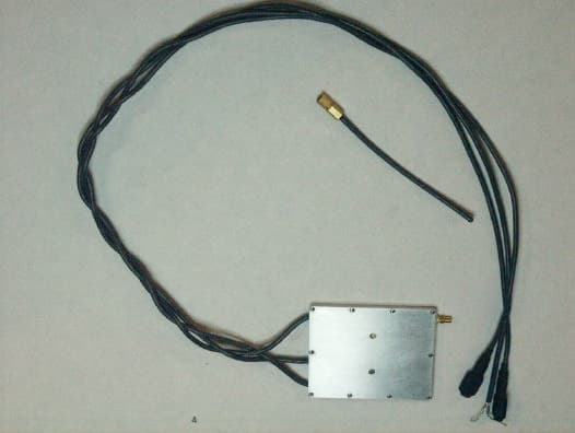
Click to zoom
Application Details
- Equipment Class
- DTS - Digital Transmission System
- Date of Grant
- Mar 16, 2005
- Application Purpose
- Original Equipment
- Date of Application
- Mar 16, 2005
- Equipment Note
- DIGITAL STEREO TRANSMITTER
- Frequency Range
- 907.00000000 - 924.00000000
- Country
- United States
Documents & Files
Document Text
Text extracted from the exhibit documents filed with the FCC. Open a document above to read the original.
Users Manual
1 1.0 INTRODUCTION. 1 1.1 THE DST1000 DIGITAL STEREO TRANSMITTER. The DST1000 is a digital wireless stereo transmitter, which offers extremely high quality audio response. It provides input for two electret microphones, and uses a stereo analog-to-digital converter and a digital RF operating at selected UHF frequencies. Because the radio transmission is truly digital in nature, a companion Tektron digital receiver (the DSR1000) delivers audio signals, which are nearly indistinguishable from a hard-wire connection to the DST1000 microphones. The unique characteristics of this transmitter also contribute to a simple and user- friendly operating environment. These include: dual channels of information transmitted from a single antenna, two microphones cables, and a power cable. The user has flexibility to use a preferred microphone style and has considerable leeway in using a power source fitting a variety of operational requirements regarding size, type and duration 2 1.1.1 THE DST1000 SUMMARY OF FEATURES. - Two 16 bit channels, 40 Hz to 16 KHz bandwidth. - 90 dB dynamic range with 0.01% distortion, exclusive of microphones. - Wide dynamic range obtained without AGC. - Forward Error Correction included. - External microphones on attached 18-inch cables. - Power cable. - Fully enclosed metal case. - 1.68” x 2.12” x 0.165” overall size. - SSMC antenna connector (flexible antenna supplied). - 1000 mW or 500 mW output power, user select. - Multi-channel. - <2.5 ounces total weight. 3 1.1.2 TRANSMIT POWER AND CHANNEL SELECT SWITCHES. Figure 1. Location of the Channel and Power Select Switches on the DST1000 Chassis. The black dot at the channel select switch indicates the position of the lowest channel frequency. The channel frequency is incremented by turning the switch in the clockwise direction. One end of the slot in both the channel select and the power select switch has two markers: this end is represented as the head of the arrow in Figure 1. The black dot at the power select switch indicates that the transmitter is operating at 1 Watt output power. Turning the switch to the dash line reduces the output power to 0.5 Watt. Antenna Channel Switch Power Switch 4 1.2 THE DST1000 CONNECTOR NOMENCLATURE. An SSMC male connector is used for the antenna. The AEP mating antenna connector is part no. 7002-1541-010. AEP connectors are available from: Applied Engineering Products 104 John W. Murphy Drive New Haven, CT 06513 Telephone: 1-800-444-5366 1.3 DST1000 PACKING LIST. 1 each DST1000 Digital Stereo Transmitter Serial No. 1 each DST1000 Antenna. 1 each DST1000 Operating Manual. 5 2.0 DST1000 SPECIFICATIONS. All performance specifications are typical at +25 0 C, unless otherwise noted. Audio Channels 2 (left/right stereo) Microphones External electret required (not supplied) Microphone Power 1.8 VDC @ 50 uA Analog S/N Ratio 86 dB (max. input to "A" weighted noise) * Total Harmonic Distortion 0.01% (max. input @ 1 KHz) * Audio Frequency Response 40 Hz to 16 KHz, @ -6 dB * 200 Hz to 15 KHz, +.5/-.5 dB * Stereo Separation 80 dB (40 Hz to 16 KHz) * Audio Gain 30 dB (microphone input to receiver output)* * Exclusive of microphone, measured at Tektron digital receiver analog output. Digitization 16 bit Linear Sigma-Delta A/D Conversion Anti-Alias Filter Linear Phase Digital Filter 0.01 dB Passband Ripple, 80 dB Stopband Atten. Sampling Rate 32 KHz Sampling Accuracy +/- 50 ppm, -10 to +50 0 C Information Rate 1.024 MBit/second Coding Rate 1/2 Forward Error Correction Signaling Rate 2.048 MBit/second 6 2.0 DST1000 SPECIFICATIONS (Continued). Transmission Frequency 8-Channel, selectable (contact factory for frequency options). FCC certified 902-928MHz Frequency Stability +/- 0.05%, -10 to +50 0 C Modulation Minimum Shift Keying RF Spectrum Evenly distributed about channel center RF Bandwidth 2 MHz @ 10 dB below peak density Power Output 1000 mW into 50 ohm load @ 5.5-14 VDC 500 mW into 50 ohm load @ 4-14VDC Antenna Impedance 50 ohms (less than 5:1 VSWR) Antenna Whip supplied Antenna Connector SSMC Jack (male) External Power 4.0 to 14 VDC negative ground DC to RF Efficiency >50% Operating Temperature Range -20 to +60 0 C Storage Temperature Range -40 to +80 0 C Size 1.68 x 2.12 x 0.165 inches Weight less than 2.5 ounces 7 3.0 DST1000 OPERATION. 3.1 BATTERY POWER. Power is supplied externally through the power cable. The red and white wires are to be connected to the positive terminal of the power source, with the black and shield wires to be connected to the negative terminal. The wiring diagram for connecting power to the unit is presented in Figure 2. Figure 2. Power Connection Wiring Diagram. IMPORTANT: The DST1000 uses internally attached power and microphone cables. DO NOT PULL ON THE CABLE. 8 3.1.1 RF OUTPUT POWER. The DST1000 is designed to operate over a voltage range of 4.0 – 14 VDC. The RF output power and DC current consumption will change as the DC voltage varies. Figure 3 charts the change in RF output power vs. DC voltage for both RF power settings of 1000 mW and 500 mW. The minimum voltage for 1 Watt (1000 mW) operation is 5.5V and for operation at 0.5 Watt (500 mW), 4V is required. 3.1.2 BATTERY CURRENT CONSUMPTION. Figure 4 shows the relationship between current and voltage. The maximum current is indicative of the required minimum voltage for operation at 1 Watt and 0.5 Watt. Figure 4 shows that for operation at 1 Watt (the black graph) a minimum battery voltage of 5.5V is required and that operation at 500 mW (the gray graph) requires a minimum voltage of 4V. Note that after 5.5V is applied for 1 Watt operation the DC power consumed is constant. For example at 10Vdc the current consumption is about 200mAdc (DC Power is 2 Watts) and at 8Vdc the current consumed is 250mAdc (DC power is 2 Watts). This shows that the DC to RF efficiency is 50% and constant above 5.5VDC for 1 Watt operation. Figure 3 Transmit Power vs. Battery Voltage 200 300 400 500 600 700 800 900 1000 1100 3456789101112131…
Text truncated - open the document above for the full version.
ID Label/Location Info
DIGITAL STEREO TRANSMITTER MODEL DST-1000 REV SERIAL NO. FREQUENCY CHANNEL FCC ID: L P T D S T 1 0 0 0 Tektron Micro Electronics Inc 7483B Candlewood Road Hanover, Maryland 21076 (410) 850-4200 MADE IN USA Operation is subject to the following two conditions: 1) This device may not cause harmful interference. 2) This device must accept any interference that may be received, including interference that may cause undesired operation.
Test Report
M. Flom Associates, Inc. 3356 N. San Marcos Place, Suite 107 Page 7 of 19 Amended 3/17/05 Chandler, Arizona 85225-7176 LPTDST1000 (480) 926-3100 phone, fax (480) 926-3598 MFA p04c0005, d510020 Name of Test: Maximum Peak Output Power Specification: 47 CFR 15.247(b) Spec. Limit: = 1 Watt peak (0.25 if <50 Hopping Channels) Test Equipment: Attached Measurement Data Radiated Antenna Gain, dBi = 2.5 Peak Output Power, Watts = 0.977 (32.4 – 2.5 = 29.9) Worst Case For All Channels Radiated: High Power g04c0016: 2004-Dec-08 Wed 09:14:00 Frequency Tuned, MHz Frequency Emission, MHz Meter, dBuV CF, dB mV/m @ 3m EIRP, dBm ERP, W 907.264000 907.277000 92.90 34.27 2282.96 31.9 <0.977 915.456000 915.469000 92.98 34.62 2398.83 32.4 0.977 923.648000 923.661000 92.01 34.98 2236.14 31.8 <0.977 Measurement Data Conducted g0530018: 2005-Mar-15 Tue 10:27:00 Frequency Tuned, MHz Power Setting ERP, dBm ERP, W 915.00000 High 30.0 1.0 915.00000 Low 27.0 0.5 Please note that this device complies with the 8 dbm limit for Spectral Power Density. Supervised By: David E. Lee, Compliance Test Manager
Test Setup Photos
M. Flom Associates, Inc. 3356 N. San Marcos Place, Suite 107 Page 9 of 19 Chandler, Arizona 85225-7176 LPTDST1000 (480) 926-3100 phone, fax (480) 926-3598 MFA p04c0005, d510020 Test Setup: Radiated Emissions State: State:
Contact Information
Applicant
Ron Briggman(Project Manager)
Test Firm
Compliance Testing, LLCMichael Schafer
Technical Specifications
| # | Rule Parts | Frequency Range | Power Output |
|---|---|---|---|
| 1 | 15C | 907 MHz - 924 MHz | 1 W |
Other Applications from Tektron Micro Electronics Inc
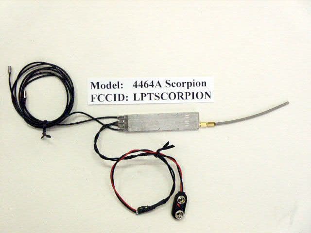
LPT-SCORPION
Apr 01, 2003Used by Police For Surveillence
Equipment Class
DXX - Part 15 Low Power Communication Device TransmitterLPT-DSR100-D0494
May 29, 1995Digital Stereo Receiver
Equipment Class
CYY - Communications Receiver used w/Pt 15 TransmitterLPT-DST100-D0481
May 23, 1995Maximum Output Power: 100 mW, Operating and marketing of this device is subject to the conditions listed in the waiver dated November 18, 1994.
Equipment Class
DXX - Part 15 Low Power Communication Device Transmitter