LRUSVR-200LA29-50MHz LOW BAND TRANSCEIVER
Pyramid Communications
Click to zoom
Application Details
- Equipment Class
- TNB - Licensed Non-Broadcast Station Transmitter
- Date of Grant
- Apr 26, 2006
- Application Purpose
- Original Equipment
- Date of Application
- Apr 26, 2006
- Equipment Note
- 29-50MHz LOW BAND TRANSCEIVER
- Frequency Range
- 29.00000000 - 50.00000000
- Company
- Pyramid Communications
- Country
- United States
Documents & Files
Document Text
Text extracted from the exhibit documents filed with the FCC. Open a document above to read the original.
Users Manual
LALA VHF: 29 - 50 MHz Page 1 SVR-200 Service Manual SVR-200 Vehicular Repeater This manual is intended for use by qualified technicians and includes all necessary information pertaining to the SVR-200 operation, circuit design and maintenance. Changes that occur after date of printing will be incorporated in supplemental service publications. Page 2 SVR-200 Service Manual Foreword Scope of this manual This manual contains the specifications, functional description, operating instructions, schematic, parts locator and parts list for the SVR-200 synthesized vehicular repeater. This manual is intended for use by qualified service technicians to aid them with installation, interfacing, alignment and trouble shooting of the SVR-200 when used with other land mobile radios. Service manual revisions Component changes, additions and deletions may occur in the circuit design to improve operation and will be reflected in future releases of this service manual. Specifications and circuit changes are subject to change without prior notice or obligation by Pyramid Communications. Safety Information The SVR-200 is designed to operate within all applicable Federal regulations at the time of manufacture. Proper operation and service procedures will assure continued compliance with these regulations: •Do not operate the SVR-200 without an antenna or appropriate RF load connected to the antenna connector. •Do not operate the SVR-200 in the presence of unshielded electrical blasting caps or explosive environmental conditions. •Do not operate the SVR-200 while refueling the vehicle or in the presence of explosive fumes. •Do not operate the SVR-200 with persons standing closer than 2 feet from the mobile or repeater antenna. FCC information The SVR-200 complies with the FCC rules parts 90 and 22 for radio frequency transmitters. The user must apply for a license to operate the SVR-200 transmitter pursuant to parts 90.243 and 90.247. Other FCC rules may apply depending on the class of service the user qualifies for. A complete listing of FCC rules and regulations may be ordered from: Superintendent of Documents Government printing office Washington DC 20402 The following information pertaining to the SVR-200 should be included in the FCC license application: Type Acceptance:LRUSVR-200LA Output Power:0.25-2.0W Emission designator: 20K0F3E Frequency band:29-50 MHz Number of Channels:1/14 Page 3 SVR-200 Service Manual Specifications Transmitter:VHF Frequency Range:29-50 MHz (29-44 MHz and 36-50 MHz) Rf power out:250mW - 2W Spurious emissions:-50dBc Freq stability -30°~+60°C:15 PPM Modulation:20K0F3E Hum and Noise:-40 Audio response (300-3kHz): Flat or +6dB/octave Audio distortion:<3% @ 60% deviation Local mic sensitivity:300mV-5VPP FCC Type Acceptance:LRUSVR-200LA Industry Canada Approval:2390 XXX XXX Receiver: Frequency Range:29-50 MHz RF sensitivity:.35μV Squelch sensitivity:.2μV to 2μV adjustable Modulation acceptance:±7.5 Selectivity:60dB Spurious/image rejection:60dB IMD response:60dB Frequency stability:1.5 PPM Audio response (300-3kHz):Flat or -6db/octave Audio output:0-5VPP AC coupled Local Rx Audio:400 mW 8 Ohms Power Requirements: DC Supply13.6 VDC Standby170 mA Receive250 mA Transmit1 A @ 2W Physical: Dimensions:5.275"W x 6"L x 1.12"H Weight:18 oz. Case:One piece extruded aluminium Page 4 SVR-200 Service Manual Functional Description Generally, vehicular repeaters are used as mobile extenders in cross-band operation: the link is VHF Low Band simplex and the mobile is Lo-band, VHF, UHF or trunking. In-band operation is possible, but care must be taken to prevent interference between the mobile's higher power transmitter and the repeater receiver. Proper frequency selection and antenna placement are important even in cross-band operation, but especially for inband use. The use of low power pre-selector cavities may be placed in line with the repeater antenna cable since it is simplex and low power. Important Note The SVR-200 operates on simplex frequencies; part of the multi-vehicle format dictates that all of the SVR-200s must be able to monitor all link traffic on site and be able to determine if a handheld is transmitting, or if other repeaters are transmitting. The handhelds must transmit CTCSS, but should be carrier squelch receive. The handhelds should not use CTCSS decode if the repeater is utilizing the multi-vehicle format, as this will interfere with the priority sampling which is essential for multi-vehicle operation. Also, the handhelds would have to have different encode and decode tones in order for the repeater to be able to tell the difference between handhelds and other repeaters, so the handhelds would not be able to hear each other. The repeaters should not transmit CTCSS unless used only in a single vehicle environment. When the user leaves the vehicle, they activate the SVR-200 via their mobile radio front panel or a separate switch. When the mobile radio is receiving carrier and proper tone, the SVR-200 will begin transmitting on the handheld’s receive frequency. The user is able to hear and respond to all radio traffic, including other handhelds at the site. The SVR-200 can be programmed to give the handhelds priority in a conversation by periodically sampling for handheld activity (carrier and proper tone) during base-to-portable transmissions. During sampling, if the SVR-200 detects a handheld transmission, it will cease transmissions, key the mobile radio and repeat portable-to-base. This allows the handheld to respond during repeater hang time or during full duplex interconnect calls. Priority sampling can be enabled/disabled through PC programming and the interval can be programmed between .25 seconds and 2.5 seconds in .25 second increments. The SVR-200 has a fixed 3 minute time out timer for base-to-portable transmissions. If the mobile COR is active for more than 3 minutes (and the SVR-200 is the priority unit) it will send a double blip and cease transmission until the mob…
Text truncated - open the document above for the full version.
External Photos
Top View: Bottom View: Rear View: Side View: Left Side View Right Front View
ID Label/Location Info
FCC ID and IC Label Format and Proposed Location Proposed Location
Internal Photos
Top View: Circuit Board Solder side of circuit board Low Band RF Board Bottom view Low Band RF Board Top view
Operational Description
Pyramid Model #: SVR-200 Transmitter Type: LRUSVR-200LA Exhibit A Subpart 2.983 (d)(10)(11) Circuit Description Receiver The receiver is a double-conversion super heterodyne type designed for narrow band FM reception. The first local oscillator is derived from the frequency synthesizer. The second LO is crystal controlled. RF Stage: The incoming RF signal from the antenna jack is directed to the RF input stage by the antenna switch U7. The RF signal is presented to the discrete band pass filter and then to the input of RF amplifier Q1. The RF signal is then presented to a second discrete band pass filter. First LO: The first LO signal is developed by the synthesizer and is output to the mixer Q2. First Mixer: The RF signal is mixed with the first LO signal by Q2. The difference component (70 MHz) is filtered by crystal filters FL1A/FL1B and applied to Q3 the 1 st IF amp. Second LO/Mixer: The first I.F. signal is presented to U1, which performs the function of second LO, second I.F. amp and mixer, FM discriminator and squelch. X1 (69.545 MHz) is the second LO crystal and is mixed with the 70 MHz first I.F. signal to produce the second I.F. frequency of 455kHz. Ceramic filter FL2 provides selectivity for the 455 kHz signal. Detector/Squelch: U2 demodulates the 455kHz signal via quadrature coil L21 to produce the audio and noise components. The output of U2 is the recovered audio and the RSSI voltage (receiver signal strength indicator), which is compared by the controller board with a threshold voltage level for squelch setting. Transmitter The output of the VCO is input to pre-amps U5 and U6. After initial amplification the output is fed into the driver Q6 before being input to final PA Q7. The final amp is an RF MOSFET power amplifier and drives the discrete low pass filter. U7 is the transmit antenna switch controlled by Q2. Page: A8 LRUSVR-200LA Exhibit A Subpart 2.983 (10)(11) Control Board Power Supply: DC power comes from the mobile radio via P1 pins 1 and 5. Fuse F1 and MOV VAR1 provide over current and voltage spike protection. Q3 is the remote enable/disable pass switch, controlled by Q1 and Q2 via pin 3. Q3 output is switched 12VDC and is presented to audio amp U6, and voltage regulators U7 and U8. Bias voltage for the op-amp circuits is provided by voltage divider R68, R60 and buffer amp U2A. Transmit audio path: Receiver audio from the mobile is input to the mic amp portion of U4; PC programming of the SVR-200 provides flat response or +6db/octave pre-emphasis. The output of the mic amp is internally connected to the limiter and low pass filter. When a condition to repeat exists (base to handheld) U4 audio is switched on and audio is presented to amplifier/limiter and low pass filter to remove audio components above 3kHz. U4 provides –48db/octave of attenuation to out of band signals. Transmit audio is output on pin 22 of U4 and passes through the final low pass filter U2C to remove any clock noise generated by U4’s switched capacitive filters before being presented to the RF module on P2 pin 6. Receive audio path: Receiver audio from the transceiver module is input on P2 pin 13 and presented to U5 pin 10 and pin 16. Pin 10 is the input of the receiver high pass filter to remove any sub audible signals before being output on pin 11 and sent to U4 for receiver audio processing. Pin 15 is the input to the sub-audible tone decoder section of U5. Receive audio entering pin 7 on U4 is processed as flat, or –ddb/octave depending on PC programming. The receive audio then passes through the internal low pass filters to remove unwanted noise and output on pin 21, where it is sent to the local receiver audio amp and mobile transmit audio output amp U1B. J1 selects either high sensitivity (open) or low sensitivity (shorted) and J2 selects the output impedance (600/2.2K Ohms). Sub-Audible tone signaling: U5 processes the sub-audible signal from the receiver by comparing the incoming signal to previous samples in a noise correlator. If the signal is sufficiently coherent, the output of the comparator is counted by the internal circuitry and an interrupt is generated to the main microprocessor. U12 reads the data from U5 in 2 bytes: byte one contains the number of internal clock cycles elapsed for the remainder. U12 performs a comparison of minimum and maximum values allowed in a look up table and determines if the data is within the decode bandwidth for the programmed tone. IN band tone signaling: Audio from the transceiver is also fed to U3B where it is amplified and limited for input to the commutation switched capacitive filter made up by C23-C26 and PO.4-Po.7 of the microprocessor. The microprocessor outputs four identical signals with 90°phase difference on the incoming respective port pins. The resultant waveform will be a function of the difference between the incoming signal frequency and the decode frequency output by the microprocessor. The signal is buffered by U3C and amplified by U3A before being rectified and filtered by D1 and C2. The resulting DC voltages comparted to the reference voltage by U3D. If the incoming signal is within the decode bandwidth, the output of U3D will be a logic of 1 and read by the microprocessor. Logic and control: U12 provides all of the logic and control functions for the repeater including mobile/repeater PTT output, local mobile PTT sense, mobile transmitter activity sense, audio switching, in-band and CTCSS detect, and repeater status indications via D2 and D3 led arrays.
Parts List/Tune Up Info
Page 18 SVR-200 Service Manual Parts List ReferenceDescriptionPart # C1,C5,C6,C9,C10,C12,C15,C18,C35,C37......................... .1μFd chip capacitor ............................1010-03-5104 C2 ..................................................................................... 22μFd 16V tantalum chip capacitor ..... 1610-25-6226 C3,C27.............................................................................. .047μFd chip capacitor ........................ 1010-03-5473 C7,C8,C13,C41................................................................. 220pFd chip capacitor .........................1010-03-5221 C11 .................................................................................... .0033μFd chip capacitor ......................1010-03-5332 C16 .................................................................................... 1000pFd chip capacitor .......................1010-03-5102 C17 .................................................................................... .0022μFd chip capacitor ......................1010-03-5222 C19,C20............................................................................ 22pFd chip capacitor ...........................1010-03-5220 C40 .................................................................................... 0.5pFd chip capacitor ..........................1010-03-5050 C21A,C21B...................................................................... 6.8μFd tantalum chip capacitor ...........1610-05-6685 C22,C32,C33,C34............................................................. 100μFd elctrolytic cap .........................1400-08-7107 C21,C23,C24,C25,C26...................................................... 0.47μFd tantalum chip capacitor .........1610-04-6474 C28,C29,C36..................................................................... 1.0μFd tantalum chip capacitor ...........1610-04-6105 C14,C30,C38..................................................................... 2.2μFd tantalum chip capacitor ...........1610-04-6225 D1,D2,D3,D6.................................................................... BAV99 dual diode SOT23 ..................3110-01-0099 D4,D5............................................................................... Schotkey diode SOT23 ........................ 3110-01-0301 DS4/DS5 ...........................................................................8 position multi-color LED .................. 4003-08-0200 F1 ...................................................................................... 2A SMT Pica fuse ..............................2610-04-0020 JP1 .................................................................................... 0.1" 3 position vertical header .............7300-53-0103 P1 ...................................................................................... DB-9 M right angle PCB .................... 7400-00-0011 P2 ...................................................................................... 0.1" 14 position vertical header ...........7300-83-0114 P3 ...................................................................................... 2.5mm RA programming jack ............. 7401-02-0250 P4 ...................................................................................... 3.5mm RA speaker jack ..................... 7401-02-0051 Q1,Q2,Q6,Q7,Q9,Q10....................................................... 2N4401 NPN transistor SOT23 ..........3010-01-4401 Q3 ..................................................................................... IRF-9540 P Ch MOSFET TO220 .......3300-08-9540 Q4 ..................................................................................... TIP 32 PNP transistor TO220 ............ 3000-08-0032 Q5 ..................................................................................... 2N4403 PNP transistor SOT23 ........... 3010-01-4403 Q8 ..................................................................................... NPN Darlington SOT23 ...................... 3010-01-0038 RV1,RV8,RV9,RV10....................................................... 10K 3mm SMT pot .............................2030-08-8103 RV2,RV3,RV5,RV7 ......................................................... 100K 3mm SMT pot ...........................2030-08-8104 RV4 .................................................................................. 20K 3mm SMT pot ............................. 2030-08-8203 RV6 .................................................................................. 200K 3mm SMT pot ........................... 2030-08-8204 R82 .................................................................................... 10 Ohm chip resistor ...........................2010-03-5100 R10,R23,R41,R52,R76...................................................... 10K chip resistor .................................2010-03-5103 R8,R11,R16,R21,R22,R24,R26,R30,R35,R44, R47,R53,R66,R73............................................................. 100K chip resistor ...............................2010-03-5104 R1,R2,R4,R6,R15,R17,R18,R31,R36,R74,R83.................. 22K chip resistor .................................2010-03-5223 R3,R12,R13,R65,R72,R87................................................. 2.2K chip resistor ................................2010-03-5222 R5,R14,R86....................................................................... 820 Ohm chip resistor .........................2010-03-5821 R7,R48,R49,R63,R71........................................................ 5.6K chip resistor ................................2010-03-5562 R9,R81.............................................................................. 56K chip resistor ................................. 2010-03-5563 R19,R20............................................................................ 470K chip resistor ............................... 2010-03-5474 R25,R29,R34,R51............................................................. 1.0M chip resistor .......................…
Text truncated - open the document above for the full version.
Parts List/Tune Up Info
FCC Type Acceptance Application Submitted By: Pyramid Communications 15182 Triton Lane #102 Huntington Beach, CA 92649 Mahesh Kiwalkar, RF Engineer Prepared: March 10, 2006 Pyramid Model #: SVR-200 Transmitter Type: LRUSVR-200LA Test Site: 15182 Triton Lane #102 Huntington Beach, CA 92649 Timco Engineering Inc. 849 NW State Road 45 Newberry FL 32669 Prepared in accordance with the requirements of FCC Rules and Regulations Part 2, Subpart F, Paragraphs 2.983 through 2.999 and applicable Portions of parts 22 and 90 LRUSVR-200LA Page: A3 LRUSVR-200LA Exhibit A Subpart 2.983 (d)(9) Alignment and Tuning Procedure Note: See Adjustment and Test point locations on page A7. Connect the test equipment as shown in Figure 1 on page A6. SVR-200 Transmitter 1. Transmitter Output: Short J3 and adjust RV10 for desired power out. 2. Transmitter frequency: Adjust the TCXO on the RF board for the transmit frequency ±100 Hz. 3. Maximum deviation/lock tone deviation: Adjust RV7 (lock tone deviation) for maximum. IF the SVR-200 is programmed for sub-audible encode, adjust RV6 (CTCSS) for the off position. Adjust RV8 (repeater deviation) for 95 % of system deviation. Adjust RV7 for 60% deviation. Remove J3. 4. Mobile COR: Measure the voltage at pin 7 of SVR-200 main connector P1 and record. Set the mobile service monitor for the mobile receive frequency, 1mV RF output and CTCSS modulation of 15%. Measure the voltage again at pin 7 and record. Turn the mobile service monitor off and adjust RV1 on the SVR-200 main board for the halfway point between the two voltage readings as read at pin 2 of U1. 5. RX audio sensitivity/CTCSSS deviation: Set the service monitor connected to the mobile for the mobile receive frequency and 1mV RF output. Modulate the signal generator with a1 kHz tone at 60% deviation and CTCSS tone at 15% deviation. Ensure that the SVR-200 mobile COR and repeater PTT LED’s are on. Adjust RV5 on the SVR-200 main board for 60% deviation as read on the service monitor connected to the SVR-200. If programmed for sub-audible encode, remove the 1kHz tone deviation for tm the mobile service monitor and adjust RV6 on the SVR-200 main board for 15% deviation. Turn the RF output from the mobile service monitor off and ensure that the SVR-200 mobile COR and repeater PTT LED’s are off. 6. Local mic repeat: If the SVR-200 is programmed for local mic repeat, key the mobile local mic and inject an audio signal into the local mic to produce 60% deviation on the service monitor connected to the mobile. Confirm that the SVR- 200 repeater PTT LED is on; adjust RV2 for 60% deviation as read on the service monitor connected to the SVR-200. Unkey the mobile radio. Page: A4 LRUSVR-200LA Exhibit A Subpart 2.983 (d)(9) Receiver 1. Receiver front end: Connect a DC voltmeter to TP1 on the SVR-200 main board. Set the Service monitor connected to the SVR-200 to the generate mode, receive frequency with a 1kHz tone and 60% deviation. Adjust the RF output of the monitor for a 1VDC reading at TP1. Adjust T1 and T2 on the RF board for a maximum reading at TP1; adjust the RF output of the monitor accordingly to maintain an approximate reading of 1VDC at TP1. 2. Discriminator: Increase the service monitor RF output for 1mV. Connect a DC voltmeter to pin 13 of P2 and adjust L10 for 1.75 VDC ±25mV. 3. Repeater squelch: Adjust the service monitor RF output for .5μV. Adjust RV9 on the SVR-200 main board so the repeater COR LED is just on. Decrease the service monitor RF output to .35μV and ensure that the repeater COR LED is off. 4. Transmit audio output: Adjust the service monitor RF output for 1mV. Turn the CTCSS modulation on and set for 15% deviation. Confirm that the repeater COR, CTCSS and mobile PTT LED’s are on. Adjust RV3 on the SVR-200 main board for 60% deviation as read on the service monitor connected to the mobile radio. 5. Local RX audio: Connect an 8ohm speaker to P4 and set RV4 for the desire listening level. Turn of the CTCSS modulation of the service monitor connected to the SVR-200. Confirm that the repeater CTCSS and mobile PTT LED’s are off. 6. Change the 1kHz tone modulation to the lock tone frequency. Confirm that the PRI LED goes off after approximately .5 seconds.
Test Report
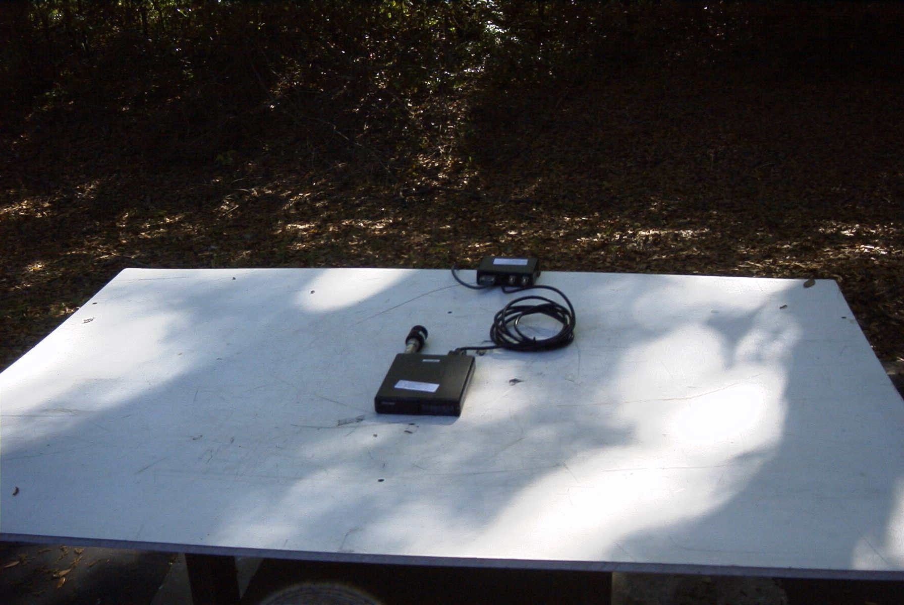
FCC Type Acceptance Application Submitted By: Pyramid Communications 15182 Triton Lane #102 Huntington Beach, CA 92649 Mahesh Kiwalkar, RF Engineer Prepared: March 10, 2006 Pyramid Model #: SVR-200 Transmitter Type: LRUSVR-200LA Test Site: 15182 Triton Lane #102 Huntington Beach, CA 92649 Timco Engineering Inc. 849 NW State Road 45 Newberry FL 32669 Prepared in accordance with the requirements of FCC Rules and Regulations Part 2, Subpart F, Paragraphs 2.983 through 2.999 and applicable Portions of parts 22 and 90 LRUSVR-200LA LRUSVR-200LA Exhibit A Subpart 2.983 Form References 1. Name of Applicant Pyramid Communications 15182 Triton Lane #102 Huntington Beach, CA 92649 [Form 731 section 1] Applicant is a vendor. 2. Identification of equipment LRUSVR-200LA [Form 731 Section 1] Low Band Transceiver [Form 731 (7) (a)] 3. Production Planned Normal mass production, 500pcs/lot 4. Technical Description (a) Types of emission 20K0F3E (b) Frequency range 29-40 MHz [Form 731 (10) (a)] 36-50 MHz (c) Range of operation power 100mW – 2W continuously variable [Form 731(10)(b)] (d) Maximum power 2W (e) DC voltage and current to final RF amplifier 9.0 VDC @ 1A Page: A5 LRUSVR-200LA Exhibit A Subpart 2.983 (d)(9) SVR Test set Knob on the front of the test set needs to be switched on and it then controls the volume of the audio when a speaker is connected to the test set. Enable is switched to ON position to turn on the SVR. When COR is switched to ON position, SVR goes into Transmit mode. Page: E7 LRUSVR-200LA Exhibit F Subpart 2.985 RF Power Output/Frequency Minimum Standard Power: 2W Frequency Tolerance: ± 20ppm maximum Measurements Frequency (MHz) Power (mW) Error (ppm) 30.1 2.00 +0.99 40.1 2.00 +0.75 50.1 2.00 +1.4 Page: F1 LRUSVR-200LA Exhibit F Subpart 2.9878(a)(1) Modulation Characteristics Frequency response of the audio modulating circuits. The SVR-200 is designed to interface to a variety of mobile radios; the receiver audio that is available may or may not be de- emphasized. Therefore PC programming provides for flat audio response, or +6db/octave pre-emphasis; both responses were measured and plotted. Frequency Flat +6db/octave pre-emphasis 200 -8 -22 300 0 -11 400 +0.3 -7.5 500 +0.5 -6 1000 0 0 1500 -0.25 +2.5 2000 -0.5 +4.5 2500 -0.75 +6 3000 -1.75 +6 3500 -5 +3 4000 -12 -1 4500 -20 -9 5000 -26 -15 Page: F2 LRU-SVR200M Exhibit F Subpart 2.9878 (a)(1) Transmit Audio Response Page: F3 LRUSVR-200LA Exhibit F Subpart 2.987(a) Audio Low pass Filter Response Frequency Response 1000 0 db 2000 -0.46 3000 -2.6 4000 -10.3 5000 -26.7 6000 -45.6 7000 -52.7 8000 -52.7 {Noise Floor} 9000 -52.7 10000 -52.7 12000 -52.7 14000 -52.7 16000 -52.7 18000 -52.7 20000 -52.7 Page: F4 LRUSVR200-M Exhibit F Subpart 2.987 (b) Modulation Characteristics Limiter Response 5kHz Maximum Deviation 30.1 MHz Input Level 300 Hz 1.0kHz 2.5 kHz 0dB 1.60 1.60 1.60 2 2.01 2.08 2.00 4 2.52 2.60 2.60 6 3.04 3.25 2.84 8 3.76 3.88 3.06 10 4.55 3.97 3.10 12 4.60 4.02 3.16 14 4.62 4.10 3.20 16 4.71 4.15 3.22 18 4.72 4.12 3.24 20 4.75 4.20 3.24 22 4.76 4.20 3.26 24 4.75 4.20 3.26 26 4.75 4.20 3.25 28 4.75 4.20 3.26 30 4.75 4.20 3.26 Page: F5 LRUSVR-200LA Exhibit F Subpart 2.987 (b) Modulation Characteristics Limiter Response 5kHz Maximum Deviation 40.1 MHz Input Level 300 Hz 1.0kHz 2.5 kHz 0dB 1.60 1.60 1.60 2 2.03 2.04 2.07 4 2.53 2.60 2.60 6 3.16 3.30 2.97 8 3.93 3.84 3.14 10 4.52 3.99 3.25 12 4.61 4.03 3.31 14 4.65 4.11 3.34 16 4.67 4.17 3.35 18 4.68 4.17 3.40 20 4.68 4.20 3.41 22 4.71 4.24 3.41 24 4.76 4.25 3.38 26 4.76 4.28 3.42 28 4.76 4.33 3.36 30 4.77 4.33 3.4 Page: F6 LRUSVR-200LA Exhibit F Subpart 2.987 (b) Modulation Characteristics Limiter Response 5kHz Maximum Deviation 50.1 MHz Input Level 300 Hz 1.0kHz 2.5 kHz 0dB 1.60 1.60 1.60 2 2.18 2.08 2.07 4 2.83 2.52 2.64 6 3.47 3.40 3.03 8 4.07 3.72 3.10 10 4.31 3.89 3.18 12 4.45 4.03 3.21 14 4.53 4.12 3.24 16 4.58 4.16 3.28 18 4.63 4.20 3.3 20 4.68 4.20 3.34 22 4.69 4.24 3.32 24 4.69 4.25 3.31 26 4.66 4.25 3.33 28 4.65 4.26 3.42 30 4.69 4.23 3.44 Page: F7 LRUSVR-200LA Exhibit F Subpart 2.989 {c}(1) Occupied Bandwidth 20 kHz Channel Spacing 30.1 MHz Emission 20K0F3E The SVR-200 transmits voice and single tone frequencies in the 300-3000 bandwidth; emissions are amplitude limited and band limited by high pass and low pass filters per the previous sections. The following plot was made with a 2.5 kHz tone at 16db above 50% level for 1kHz (per EIA-152C). Page: F8 LRUSVR-200LA Exhibit F Subpart 2.989 {c}(1) Occupied Bandwidth 20 kHz Channel Spacing 40.1 MHz Emission 20K0F3E The SVR-200 transmits voice and single tone frequencies in the 300-3000 bandwidth; emissions are amplitude limited and band limited by high pass and low pass filters per the previous sections. The following plot was made with a 2.5 kHz tone at 16db above 50% level for 1kHz (per EIA-152C). Page: F9 LRUSVR-200LA Exhibit F Subpart 2.989 {c}(1) Occupied Bandwidth 20kHz Channel Spacing 50.1 MHz Emission 20K0F3E The SVR-200 transmits voice and single tone frequencies in the 300-3000 bandwidth; emissions are amplitude limited and band limited by high pass and low pass filters per the previous sections. The following plot was made with a 2.5 kHz tone at 16db above 50% level for 1kHz (per EIA-152C). Page: F10 LRUSVR-200LA Exhibit F Subpart 2.991 Spurious emission at the antenna terminal at 2W Minimum Standard -46dbc Measurements Power 2W Frequency Level 30.1 0 dB 60.2 - 54.50 dbc 40.1 0 dB 80.2 - 54.84 dbc 50.1 0 dB 100.2 -52dbc All other spurious signals were at least 20dB below the FCC limit. Frequency spectrum was investigated out to the 10 th harmonic Page: F11 LRUSVR-200LA Exhibit F: Conducted Spurious 2W Subpart 2.991 30.1 MHz Page: F12 LRUSVR-200LA Exhibit F: Conducted Spurious 2W Subpart 2.991 40.1 MHz Page: F13 LRUSVR-200LA Exhibit F: Conducted Spurious 2W Subpart 2.991 50.1 MHz Page F14 LRUSVR-200LA Exhibit F Subpart 2.995 Minimum Standard ± 20 ppm (±600Hz) (a) Frequency stability over Temperature 30.1 MHz Temp (°C)…
Text truncated - open the document above for the full version.
Test Report
FCC PART 22 AND 90 TYPE APPROVAL TEST REPORT APPLICANT Pyramid Communications 15182 Triton Land Suite 102 Huntington Beach, CA 92649 FCC ID LRUSVR-200LA MODEL NUMBER SVR-200LA PRODUCT DESCRIPTION 29 – 50 MHz Low Band Transceiver DATE SAMPLE RECEIVED March 25, 2006 DATE TESTED March 31, 2006 Tested By Richard Block Approved By TEST RESULTS PASS FAIL THE ATTACHED REPORT SHALL NOT BE REPRODUCED EXCEPT IN FULL WITHOUT THE WRITTEN APPROVAL OF TIMCO ENGINEERING, INC. 849 NW STATE ROAD 45 NEWBERRY, FL 32669 USA PH: 888.472.2424 OR 352.472.5500 FAX: 352.472.2030 EMAIL: [email protected] HTTP://WWW.TIMCOENGR.COM APPLICANT: Pyramid Communications FCC ID: LRUSVR-200LA REPORT: V:\P\pyramidcomm\575AUT6\575AUT6 Test Report 2 - TEI.doc Page 2 of 6 Table of Content FIELD STRENGTH OF SPURIOUS EMISSIONS........................................ 3 Rules Part No............................................................. 3 Requirements.............................................................. 3 Test Method............................................................... 3 Test Setup................................................................ 3 Test Data................................................................. 3 EMC EQUIPMENT LIST.......................................................... 5 TEST SETUP PHOTO............................................................ 6 APPLICANT: Pyramid Communications FCC ID: LRUSVR-200LA REPORT: V:\P\pyramidcomm\575AUT6\575AUT6 Test Report 2 - TEI.doc Page 3 of 6 FIELD STRENGTH OF SPURIOUS EMISSIONS Rules Part No.: Part 2.1053 Requirements: Emissions must be 43 +10log(Po) dB below the mean power output of the amplifier: 43 + 10log(2.00) = 46 dB Test Method: The tabulated data shows the results of the radiated field strength emissions test. The spectrum was scanned from 30 MHz to at least the tenth harmonic of the fundamental. This test was conducted per TIA/EIA STANDARD 603 using the substitution method. Measurements were made at the open field test s…
Text truncated - open the document above for the full version.
Contact Information
Applicant
Christopher Carbajal(Vice President of Engineering)
Test Firm
Timco Engineering, Inc.Sid Sanders
Technical Specifications
| # | Rule Parts | Frequency Range | Power Output | Emission | Tolerance |
|---|---|---|---|---|---|
| 1 | 22,90 | 29 MHz - 50 MHz | 2 W | 20K0F3E | 20.0000000000 ppm |
Other Applications from Pyramid Communications

LRUSVR-250V
Dec 27, 2010VHF Mobile Radio
Equipment Class
TNB - Licensed Non-Broadcast Station Transmitter
LRUSVR-250U
Dec 27, 2010Vehicular Repeater
Equipment Class
TNB - Licensed Non-Broadcast Station Transmitter
LRUSVR-200M
Feb 03, 2004LOW POWER VEHICULAR REPEATER
Equipment Class
TNB - Licensed Non-Broadcast Station TransmitterLRUSVR-200VB
Oct 20, 1996Single Channel Mode
Equipment Class
TNB - Licensed Non-Broadcast Station TransmitterLRUVR-100U
Sep 14, 1994TNB - Licensed Non-Broadcast Station Transmitter
Equipment Class
TNB - Licensed Non-Broadcast Station Transmitter