LSD66THandheld Garage Door Type RF
DoorKing Inc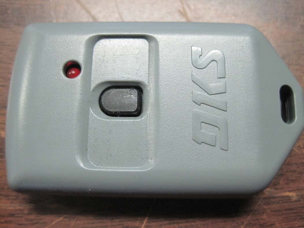
Click to zoom
Application Details
- Equipment Class
- DSC - Part 15 Security/Remote Control Transmitter
- Date of Grant
- Mar 09, 2010
- Application Purpose
- Original Equipment
- Date of Application
- Mar 07, 2010
- Equipment Note
- Handheld Garage Door Type RF
- Frequency Range
- 318.00000000 - 318.00000000
- Company
- DoorKing Inc
- Country
- United States
Documents & Files
Document Text
Text extracted from the exhibit documents filed with the FCC. Open a document above to read the original.
Users Manual
microplus / microclick - transmitters Interference Information This equipment may interfere with radio communications, AM/FM radio and TV re- ception. Use the following suggestions to correct the interference: • Relocate the receiving antenna. • Increase the space between the equipment and transmitter receiver. • Connect the equipment into another outlet, diff erent from the transmitter receiver. • Consult a technician for help. This equipment has been certifi ed to comply with the limits for a class B computing device, pursuant to FCC Rules. To maintain compliance with FCC regulations, shielded cables must be used with this equipment. Operation with non-approved equipment or unshielded cables may result in interference to radio and TV reception. This Class [B] digital apparatus meets all requirements of the Canadian Interference- Causing Equipment Regulations. Cet appareil numrique de la classe [B] respecte toutesles exigences du Reglement sur le materiel brouilleur du Canada. FCC Compliance This device will provide reliable remote access control. Be aware of the following limitations: • This device complies with FCC Rules and Regulations, Part 15 and Canadian In- terference Causing Equipment Regulations. Because of this, they have limited transmitter power and limited range. Operation is subject to the following two conditions: (1) this device may not cause harmful interference, (2) this device must accept any interference received, including interference that may cause undesired operation. • The receiving device cannot respond to more than one transmitted signal at a time. Radio signals near the receiver operating frequency may block the transmit- ter signal regardless of the code setting. If this occurs, the radio receiver may have to be repositioned. • Any changes or modifi cations may void compliance with FCC Rules and Regulations. DoorKing’s transmitters are ideal for applications that require RF wireless access. Users can remain comfortably inside their vehicle while activating the RF transmitter without having to use a keypad or card reader. When activated a data stream is sent to the remote SuperHet receiver. This data includes the transmitter serial number, facility code, and button code. In addition MicroPLUS transmitters have an encrypted sync-code that changes each time the transmitter is used. Interference Information This equipment may interfere with radio communications, AM/FM radio and TV re- ception. Use the following suggestions to correct the interference: • Relocate the receiving antenna. • Increase the space between the equipment and transmitter receiver. • Connect the equipment into another outlet, diff erent from the transmitter receiver. • Consult a technician for help. This equipment has been certifi ed to comply with the limits for a class B computing device, pursuant to FCC Rules. To maintain compliance with FCC regulations, shielded cables must be used with this equipment. Operation with non-approved equipment or unshielded cables may result in interference to radio and TV reception. This Class [B] digital apparatus meets all requirements of the Canadian Interference- Causing Equipment Regulations. Cet appareil numrique de la classe [B] respecte toutesles exigences du Reglement sur le materiel brouilleur du Canada. FCC Compliance This device will provide reliable remote access control. Be aware of the following limitations: • This device complies with FCC Rules and Regulations, Part 15 and Canadian In- terference Causing Equipment Regulations. Because of this, they have limited transmitter power and limited range. Operation is subject to the following two conditions: (1) this device may not cause harmful interference, (2) this device must accept any interference received, including interference that may cause undesired operation. • The receiving device cannot respond to more than one transmitted signal at a time. Radio signals near the receiver operating frequency may block the transmit- ter signal regardless of the code setting. If this occurs, the radio receiver may have to be repositioned. • Any changes or modifi cations may void compliance with FCC Rules and Regulations. Interference Information This equipment may interfere with radio communications, AM/FM radio and TV re- ception. Use the following suggestions to correct the interference: • Relocate the receiving antenna. • Increase the space between the equipment and transmitter receiver. • Connect the equipment into another outlet, diff erent from the transmitter receiver. • Consult a technician for help. This equipment has been certifi ed to comply with the limits for a class B computing device, pursuant to FCC Rules. To maintain compliance with FCC regulations, shielded cables must be used with this equipment. Operation with non-approved equipment or unshielded cables may result in interference to radio and TV reception. This Class [B] digital apparatus meets all requirements of the Canadian Interference- Causing Equipment Regulations. Cet appareil numrique de la classe [B] respecte toutesles exigences du Reglement sur le materiel brouilleur du Canada. FCC Compliance This device will provide reliable remote access control. Be aware of the following limitations: • This device complies with FCC Rules and Regulations, Part 15 and Canadian In- terference Causing Equipment Regulations. Because of this, they have limited transmitter power and limited range. Operation is subject to the following two conditions: (1) this device may not cause harmful interference, (2) this device must accept any interference received, including interference that may cause undesired operation. • The receiving device cannot respond to more than one transmitted signal at a time. Radio signals near the receiver operating frequency may block the transmit- ter signal regardless of the code setting. If this occurs, the radio receiver may have to be repositioned. • Any changes or modifi cations may void compliance with FCC Rules and…
Text truncated - open the document above for the full version.
Block Diagram
DOORKING SYSTEMS 120 Glasgow Avenue Inglewood, CA 90301 Tel. 800-826-7493 310-645-0023 Fax 310-641-1586 e-mail: [email protected] www.doorking.com DOORKING Inc. Model 8066 Block Diagram total access control . . . . . . . . . . . . . . . . . . . . . . . . . . . . . . . . . . . . . . . . . . . . . . .
Cover Letter(s)
DOORKING SYSTEMS 120 Glasgow Avenue Inglewood, CA 90301 Tel. 800-826-7493 310-645-0023 Fax 310-641-1586 e-mail: [email protected] www.doorking.com DOORKING Inc. December 16, 2009 To Whom It May Concern: This is your letter of authorization to accept our appointment of CKC Certification Services, LLC as Agent for Doorking Inc. 120 Glasgow St. Inglewood CA 90301 to sign applications before the agency on our behalf, and to receive and exchange data between our company and the agency in connection with certification. Sincerely, Patrick Kochie, V.P of Engineering Doorking Inc.
Cover Letter(s)
DOORKING SYSTEMS 120 Glasgow Avenue Inglewood, CA 90301 Tel. 800-826-7493 310-645-0023 Fax 310-641-1586 e-mail: [email protected] www.doorking.com DOORKING Inc. 3/8/2010 Federal Communications Commission 7435 Oakland Mills Road Columbia, MD 21046 Gentlemen: This letter is to comply with Section 0.457 and Section 0.459 pertaining to confidential material. Pertaining to FCC ID: LSD66T DoorKing, Inc. does not require any exhibits provided to be held confidential. Sincerely, Patrick Kochie V.P. of Engineering Doorking, Inc.
Cover Letter(s)
Non-Conformities FCC ID : LSD66T (CKC CS Ref # E10-000015-FCC-01) The items listed below represent requests for information following review of this application for certification under United S tates (FCC) regulations. Further question may arise pending review of responses to these items. OK ID # Non-Conformity or Comment Subm itted Response Respondent / Date of Response x TL 1 On page8 of the test report 90410-5, the test condition includes a statement stating the RF switch is not pressed. From the schematic diagram, it is clear that if the switch is not pressed, the device would not be connected to the battery. Please confirm whether 15.209 was performed with the device connected to the battery and energized , and revise the test report to indicate as such. Revised test report with unnecessary 15.209 test data removed. 15.209 compliance is fulfilled under 15/213(b)/ 15.205 requirement. Test lab 3/5/10 X C 2 It is unclear whether this PWM transmitter incorporates rolling codes. Please clarify whether this transmitter incorporates rolling codes, if so, please declare the duty cycle range over which the equipment operates The 8068 transmitter does not incorporate rolling code technology. Patrick Kochie 2/26/10 X C 3 Due to Non-Conformity responses pertaining to the Model number in the IC related Application (E10-000016-IC) it is suggested that you update your FCC ID to retain consistency between these 2 applications. No action required. The report will need to be changed from 8068 to 8066. – EW I will start working on the documents today to reflect new model & ID numbers. New ID numbers: FCC: LSD66T IC 1736A-66T Updated Documents Provided. Updated the Applications and Application Reports. Saved provided Exhibits in the Temp Folder pending review. Please do a search and replace to Patrick Kochie 3/1/10 Patrick Kochie 3/1/10 Jessina Hunter 3/2/10 Patrick Kochie Unfortunately due to the scope of our accreditations we cannot search and replace the model number... ther e are only two options that are available. One is that a statemen t can be added that states... during the time of testing the product was called the 8068 but since then the manufacture has decided to change the model number to 8066. That is not the exact wording but it will be something to that effect. All the rest of the references will remain the same with this option. The other option is to strike through the model number on all data sheets and add the new model number after it. This is not a popular option because it is ugly and the change glares out at you from the report whereas adding the statement is su btle and has been accepted without any hiccups by the FCC and all other regulating bodies. The reason that we cannot simply search and replace is that A2LA (our Test Lab accreditation body) requires that any changes to the data after it has been collected cannot be removed and only a strikethrough with the correct data listed behind the strikethrough can be used. This is the way that A2LA wants the data be presented. If we wanted to change the model number currently present in the data re-testing would have to occur. –Reports correct the test re port. Replace 8068 with 8066. I had no idea thing are so formal. Whatever is easiest for you guys is fine with me. Either the strike through or the statement, e ither one is OK to use. Updated Report Provided. 3/2/10 Patrick Kochie 3/2/10 Report Department 3/3/10 The items indicated above must be submitted before processing can continue on the referenced application. Failure to provide t he requested information within 60 days may result in application dismissal pursuant to Section 2.917(c) and forfeiture of the filing fee pursuant to Se ction 1.1106. How to read the table: OK column indicates closure by CKC CS. ID column is for use with Agents to assist in identifying the probable source for closure. A – Application issue TL – Test lab issue C – Client issue R – Retesting may be necessary # column indicates unique or separate non-conformity items (note some items may be related). Non-Conformity or Comment column indicates the evaluators specific question or comment. Submitted response column indicates the response or a summary of the response provided. Respondent / Date of Response column indicates the responding party or agent and the date of the response was either received or logged.
ID Label/Location Info
DOORKING SYSTEMS 120 Glasgow Avenue Inglewood, CA 90301 Tel. 800-826-7493 310-645-0023 Fax 310-641-1586 e-mail: [email protected] www.doorking.com DOORKING Inc. Model 8066 Sample Label total access control . . . . . . . . . . . . . . . . . . . . . . . . . . . . . . . . . . . . . . . . . . . . . . .
Operational Description
DOORKING SYSTEMS 120 Glasgow Avenue Inglewood, CA 90301 Tel. 800-826-7493 310-645-0023 Fax 310-641-1586 e-mail: [email protected] www.doorking.com DOORKING Inc. Function Description of Model 8066 Handheld Garage Door Type Transmitter The transmitter consists of encoder chip, SAW stabilized RF oscillator, and a 12 volt battery to power the device. Encoder The processor/encoder chip is manufactured by Freescale Inc. The part number is MC68HC908JK1. The encoder is preprogrammed at Doorking with a serial number, which is used to later modulate the RF oscillator when the encoder is activated. The serial number is unique to each transmitter and is used to identify the transmitter. The output ( pins 19,18,17,16 ) of the encoder stays low, (RF oscillator off), until switch SW1 is closed. SW1 applies power to the entire transmitter. The encoder starts to run with the serial number and button data output in a pulse position data modulation scheme. A 1ms pulse in the middle of a 6ms data window is a transmitted data 0. A 1ms. pulse at the end of a 6ms data window is data 1. The output of the encoder turns on and off the RF oscillator at this rate. RF Oscillator/Antenna. The RF oscillator consists of a single transistor colpitts oscillator. L1,C5,C6 form the basic LC tank circuit. The oscillator is stabilized to 318MHz by SAW resonator S1. No tuning of the oscillator is needed in production. When the output of the encoder is high, the transistor is biased on and the circuit oscillates. When the encoder output is low the transistor is biased off and the oscillator does not oscillate. The oscillator is coupled to a stub antenna using L2. The stub antenna consists of a 2 inch length of printed circuit board etch. Battery/LED The transmitter is powered by a 12 volt battery, Duracell type MN21 or equivalent. The LED provides reverse battery circuit protection and transmitter operation indicator.
Operational Description
freescale.com Microcontrollers M68HC08 MC68HC908JK1 MC68HRC908JK1 MC68HC908JK3 JC68HRC908JK3 MC68HC908JL3 MC68HRC908JL3 Technical Data Rev. 1.1 MC68HC908JL3/H August 1, 2005 MC68H(R)C908JL3 — Rev. 1.1Technical Data Freescale SemiconductorList of Sections 3 Technical Data — MC68H(R)C908JL3 List of Sections Section 1. General Description . . . . . . . . . . . . . . . . . . . . 21 Section 2. Memory . . . . . . . . . . . . . . . . . . . . . . . . . . . . . . 27 Section 3. Random-Access Memory (RAM) . . . . . . . . . . 37 Section 4. FLASH Memory (FLASH) . . . . . . . . . . . . . . . . 39 Section 5. Configuration Register (CONFIG) . . . . . . . . . 47 Section 6. Central Processor Unit (CPU) . . . . . . . . . . . . 51 Section 7. System Integration Module (SIM) . . . . . . . . . 71 Section 8. Oscillator (OSC) . . . . . . . . . . . . . . . . . . . . . . . 95 Section 9. Monitor ROM (MON) . . . . . . . . . . . . . . . . . . . 101 Section 10. Timer Interface Module (TIM) . . . . . . . . . . . 115 Section 11. Analog-to-Digital Converter (ADC) . . . . . . 137 Section 12. I/O Ports . . . . . . . . . . . . . . . . . . . . . . . . . . . . 147 Section 13. External Interrupt (IRQ) . . . . . . . . . . . . . . . 159 Section 14. Keyboard Interrupt Module (KBI). . . . . . . . 165 Section 15. Computer Operating Properly (COP) . . . . 173 Section 16. Low Voltage Inhibit (LVI) . . . . . . . . . . . . . . 179 Section 17. Break Module (BREAK) . . . . . . . . . . . . . . . 183 Section 18. Electrical Specifications . . . . . . . . . . . . . . . 191 Section 19. Mechanical Specifications . . . . . . . . . . . . . 203 Section 20. Ordering Information . . . . . . . . . . . . . . . . . 207 List of Sections Technical DataMC68H(R)C908JL3 — Rev. 1.1 4List of SectionsFreescale Semiconductor MC68H(R)C908JL3 — Rev. 1.1Technical Data Freescale SemiconductorTable of Contents 5 Technical Data — MC68H(R)C908JL3 Table of Contents Section 1. General Description 1.1Contents . . . . . . . . . . . . . . . . . . . . . . . . . . . . . . . . . . . . . . . . . . 21 1.2Introduction . . . . . . . . . . . . . . . . . . . . . . . . . . . . . . . . . . . . . . . . 21 1.3Features . . . . . . . . . . . . . . . . . . . . . . . . . . . . . . . . . . . . . . . . . . 22 1.4MCU Block Diagram . . . . . . . . . . . . . . . . . . . . . . . . . . . . . . . . . 23 1.5Pin Assignments . . . . . . . . . . . . . . . . . . . . . . . . . . . . . . . . . . . . 25 1.6Pin Functions . . . . . . . . . . . . . . . . . . . . . . . . . . . . . . . . . . . . . . 26 Section 2. Memory 2.1Contents . . . . . . . . . . . . . . . . . . . . . . . . . . . . . . . . . . . . . . . . . . 27 2.2Introduction . . . . . . . . . . . . . . . . . . . . . . . . . . . . . . . . . . . . . . . . 27 2.3I/O Section . . . . . . . . . . . . . . . . . . . . . . . . . . . . . . . . . . . . . . . . 29 2.4Monitor ROM . . . . . . . . . . . . . . . . . . . . . . . . . . . . . . . . . . . . . . 29 Section 3. Random-Access Memory (RAM) 3.1Contents . . . . . . . . . . . . . . . . . . . . . . . . . . . . . . . . . . . . . . . . . . 37 3.2Introduction . . . . . . . . . . . . . . . . . . . . . . . . . . . . . . . . . . . . . . . . 37 3.3Functional Description . . . . . . . . . . . . . . . . . . . . . . . . . . . . . . . 37 Section 4. FLASH Memory (FLASH) 4.1Contents . . . . . . . . . . . . . . . . . . . . . . . . . . . . . . . . . . . . . . . . . . 39 4.2Introduction . . . . . . . . . . . . . . . . . . . . . . . . . . . . . . . . . . . . . . . . 39 4.3Functional Description . . . . . . . . . . . . . . . . . . . . . . . . . . . . . . . 40 Table of Contents Technical DataMC68H(R)C908JL3 — Rev. 1.1 6Table of ContentsFreescale Semiconductor 4.4FLASH Control Register . . . . . . . . . . . . . . . . . . . . . . . . . . . . . . 40 4.5FLASH Block Erase Operation . . . . . . . . . . . . . . . . . . . . . . . . . 41 4.6FLASH Mass Erase Operation . . . . . . . . . . . . . . . . . . . . . . . . . 42 4.7FLASH Program Operation. . . . . . . . . . . . . . . . . . . . . . . . . . . . 43 4.8FLASH Protection . . . . . . . . . . . . . . . . . . . . . . . . . . . . . . . . . . . 44 4.9FLASH Block Protect Register . . . . . . . . . . . . . . . . . . . . . . . . . 46 Section 5. Configuration Register (CONFIG) 5.1Contents . . . . . . . . . . . . . . . . . . . . . . . . . . . . . . . . . . . . . . . . . . 47 5.2Introduction . . . . . . . . . . . . . . . . . . . . . . . . . . . . . . . . . . . . . . . . 47 5.3Functional Description . . . . . . . . . . . . . . . . . . . . . . . . . . . . . . . 48 Section 6. Central Processor Unit (CPU) 6.1Contents . . . . . . . . . . . . . . . . . . . . . . . . . . . . . . . . . . . . . . . . . . 51 6.2Introduction . . . . . . . . . . . . . . . . . . . . . . . . . . . . . . . . . . . . . . . . 51 6.3Features . . . . . . . . . . . . . . . . . . . . . . . . . . . . . . . . . . . . . . . . . . 52 6.4CPU Registers . . . . . . . . . . . . . . . . . . . . . . . . . . . . . . . . . . . . . 52 6.4.1Accumulator . . . . . . . . . . . . . . . . . . . . . . . . . . . . . . . . . . . . . 53 6.4.2Index Register . . . . . . . . . . . . . . . . . . . . . . . . . . . . . . . . . . . 54 6.4.3Stack Pointer . . . . . . . . . . . . . . . . . . . . . . . . . . . . . . . . . . . . 54 6.4.4Program Counter . . . . . . . . . . . . . . . . . . . . . . . . . . . . . . . . . 55 6.4.5Condition Code Register . . . . . . . . . . . . . . . . . . . . . . . . . . . 55 6.5Arithmetic/Logic Unit (ALU) . . . . . . . . . . . . . . . . . . . . . . . . . . . 58 6.6Low-Power Modes . . . . . . . . . . . . . . . . . . . . . . . . . . . . . . . . . . 58 6.6.1Wait Mode . . . . . . . . . . . . . . . . . . . . . . . . . . . . . . . . . . . . . . 58 6.6.2Stop Mode . . . . . . . . . . . . . . . . . . . . . . . . . . . . . . . . . . . . . . 59 6.7CPU During Break Interrupts . . . . . . . . . . . . . . . . . . . . . . . . . . 59 6.8Instruction Set Summary . . . . . . . . . . . . . . . . . . . . . . . . . . . . 59 6.9Opcode Map . . . . . . . . . . . . . …
Text truncated - open the document above for the full version.
Schematics
L1 27nh L2 150nh P1 657 34182 5 1 2 34 P2 2.00" STUB ANTENNA BAT+ BAT- Q1 MMBTH10LT1 C3 470pf R4 47k S1 SAW1 C5 10pf engineer prepared checked sheet code iddrawing no. scale size no. R2 47 C8 10pf D1 LED 1 IC1 PD5 PD2 PD3 17 16 Rst 18 PD4 20 19 4 5 OSC1 OSC2 Vdd 2 1 3 IRQ Vss PB3 PB2 68HC908JK1 PB4 12 11 14 15 13 PB1 9 8 10 PB5 PD7 PD6 6 7 PB0PB7 PB6 R1 2.2meg PAD A C7 10pf Y1 3.58mhz PADC RN1 81 100k RN1 72 100k PAD D C6 33pf R3 330 VR1 O NCP551 5 I 1 2 4 EG 3SW1 PAD E C1 .1uf RN1 63 100k C2 .1uf RN1 54 100k 1 10/15/09 DATE 8093-970 PROGRAMMABLE RADIO TRANSMITTER APP 1of1 PSK DESCRIPTIONLTR ANEW DRAWING RELEASE MICROCLIK 318MHz 1 BUTTON SAW RESONATOR 318 MHZ
Test Report
This report contains a total of 26 pages and may be reproduced in full only. Partial reproduction may only be done with the written consent of CKC Laboratories, Inc. Doorking Inc. ADDENDUM TO TEST REPORT 90410 Handheld Garage Door Type RF Transmitter 318 MHz, 8066 Tested To The Following Standards: FCC Part 15 Subpart C Sections 15.205/15.231 and RSS‐210 Version 7 Report No.: 90410‐5 Date of issue: March 3, 2010 TESTING CERT #803.01, 803.02, 803.05, 803.06 This test report bears the accreditation symbol indicating that the testing performed herein meets the test and reporting requirements of ISO/IEC 17025 under the applicable scope of EMC testing for CKC Laboratories, Inc. We strive to create long‐term, trust based relationships by providing sound, adaptive, customer first testing services. We embrace each of our customers’ unique EMC challenges, not as an interruption to set processes, but rather as the reason we are in business. Page 2of 26 Report No.: 90410‐5A TABLE OF CONTENTS Administrative Information .......................................................................................................................... 3 Test Report Information ............................................................................................................................................ 3 Revision History ......................................................................................................................................................... 3 Report Authorization ................................................................................................................................................. 3 Test Facility Information ............................................................................................................................................ 4 Site Registration & Accreditation Information .......................................................................................................... 4 Summary of Results ................................................................................................................................................... 5 Conditions During Testing ......................................................................................................................................... 5 Equipment Under Test ............................................................................................................................................... 5 Equipment Under Test ............................................................................................................................................... 5 Peripheral Devices ..................................................................................................................................................... 5 FCC Part 15 Subpart C ................................................................................................................................... 6 Temperature And Humidity During Testing............................................................................................................... 6 15.31(e) Voltage Variation ......................................................................................................................................... 6 15.31(m) Number Of Channels .................................................................................................................................. 6 15.33(a) Frequency Ranges Tested ............................................................................................................................ 6 15.203 Antenna Requirements .................................................................................................................................. 6 EUT Operating Frequency .......................................................................................................................................... 6 15.231(a)(1) Release Time ......................................................................................................................................... 7 15.231(b) Field Strength of Fundamental .................................................................................................................. 9 15.231(b)/15.205 Field Strength of Spurious Radiation .......................................................................................... 15 15.231(c ) & RSS‐210 Occupied Bandwidth ............................................................................................................. 22 Appendix A: Customer Provided Information ............................................................................................. 24 I/O Ports................................................................................................................................................................... 24 Crystal Oscillators .................................................................................................................................................... 24 Printed Circuit Boards .............................................................................................................................................. 24 Supplemental Information .......................................................................................................................... 25 Measurement Uncertainty ...................................................................................................................................... 25 Emissions Test Details .............................................................................................................................................. 25 Page 3of 26 Report No.: 90410‐5A ADMINISTRATIVE INFORMATION Test Report Information REPORT PREPARED FOR: REPORT PREPARED BY: Doorking Inc. 120 Glasgow St. Inglewood, CA 90301 Joyce Walker CKC Laboratories, Inc. 5046 Sierra Pines Drive Mariposa, CA 95338 Representative: Patrick Kochie Project N…
Text truncated - open the document above for the full version.
Contact Information
Applicant
Patrick Kochie
Technical Contact
CKC Certification Services, LLCJessina Hunter
[email protected]209-966-5240
5046 Sierra Pines Dr. · Mariposa, California · United States
Test Firm
CKC Laboratories, Inc.Steve Behm
Technical Specifications
| # | Rule Parts | Frequency Range | Power Output |
|---|---|---|---|
| 1 | 15.231 | 318 MHz - 318 MHz | - |
Other Applications from DoorKing Inc
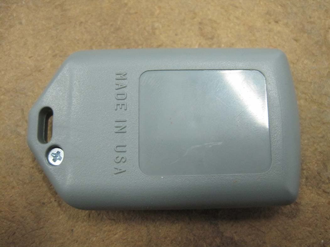
LSD72AT
Jul 07, 2010Handheld Garage Door Type RF Transmitter 418 MHz
Equipment Class
DSC - Part 15 Security/Remote Control Transmitter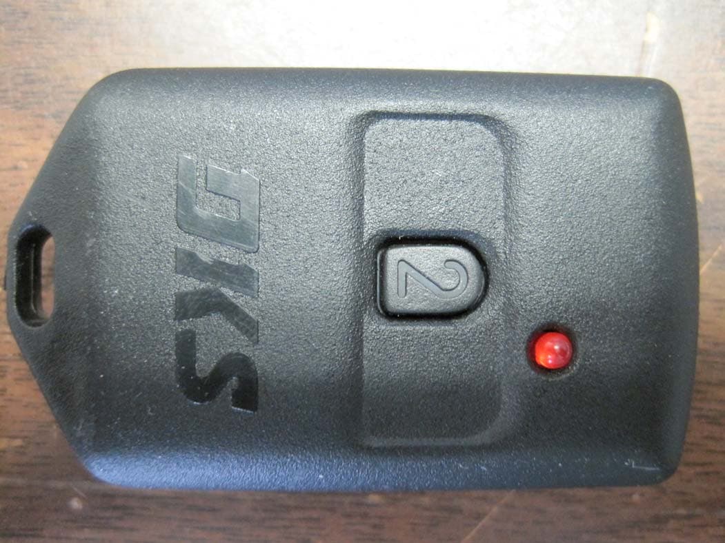
LSD69T
Jan 14, 2010Handheld Garage Door RF Transmitter
Equipment Class
DSC - Part 15 Security/Remote Control Transmitter
LSD82T
Dec 30, 1998DSC - Part 15 Security/Remote Control Transmitter
Equipment Class
DSC - Part 15 Security/Remote Control TransmitterLSD8068TX
Oct 16, 1994Remote Control Transmitter
Equipment Class
DSC - Part 15 Security/Remote Control Transmitter