LSD69THandheld Garage Door RF Transmitter
DoorKing Inc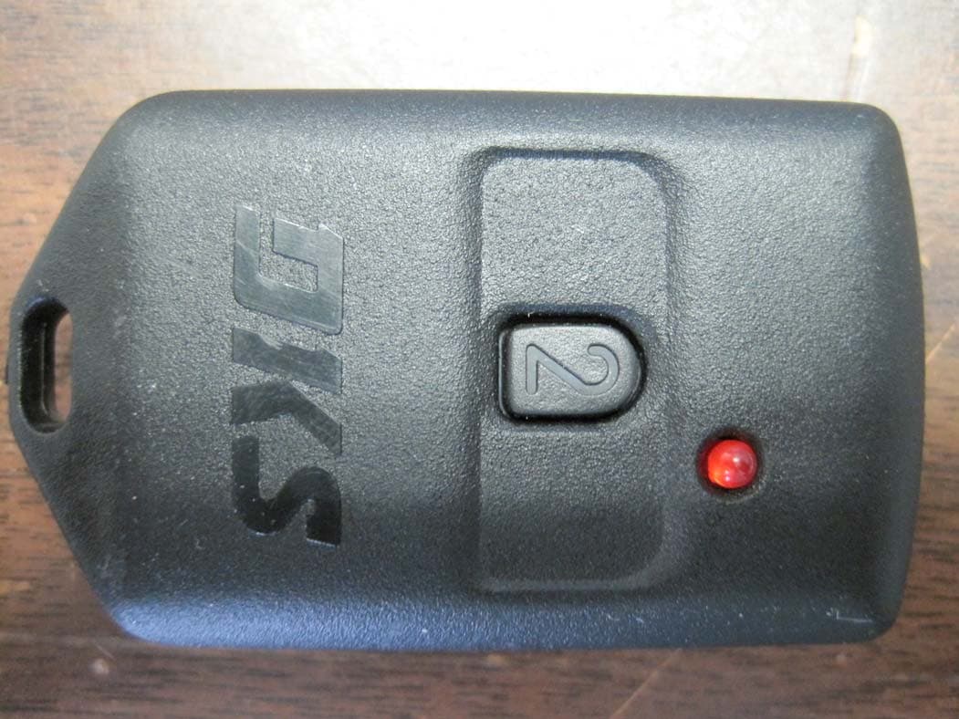
Click to zoom
Application Details
- Equipment Class
- DSC - Part 15 Security/Remote Control Transmitter
- Date of Grant
- Jan 14, 2010
- Application Purpose
- Original Equipment
- Date of Application
- Jan 13, 2010
- Equipment Note
- Handheld Garage Door RF Transmitter
- Frequency Range
- 318.00000000 - 318.00000000
- Company
- DoorKing Inc
- Country
- United States
Documents & Files
Document Text
Text extracted from the exhibit documents filed with the FCC. Open a document above to read the original.
Users Manual
microplus / microclick - transmitters Interference Information This equipment may interfere with radio communications, AM/FM radio and TV re- ception. Use the following suggestions to correct the interference: • Relocate the receiving antenna. • Increase the space between the equipment and transmitter receiver. • Connect the equipment into another outlet, diff erent from the transmitter receiver. • Consult a technician for help. This equipment has been certifi ed to comply with the limits for a class B computing device, pursuant to FCC Rules. To maintain compliance with FCC regulations, shielded cables must be used with this equipment. Operation with non-approved equipment or unshielded cables may result in interference to radio and TV reception. This Class [B] digital apparatus meets all requirements of the Canadian Interference- Causing Equipment Regulations. Cet appareil numrique de la classe [B] respecte toutesles exigences du Reglement sur le materiel brouilleur du Canada. FCC Compliance This device will provide reliable remote access control. Be aware of the following limitations: • This device complies with FCC Rules and Regulations, Part 15 and Canadian In- terference Causing Equipment Regulations. Because of this, they have limited transmitter power and limited range. Operation is subject to the following two conditions: (1) this device may not cause harmful interference, (2) this device must accept any interference received, including interference that may cause undesired operation. • The receiving device cannot respond to more than one transmitted signal at a time. Radio signals near the receiver operating frequency may block the transmit- ter signal regardless of the code setting. If this occurs, the radio receiver may have to be repositioned. • Any changes or modifi cations may void compliance with FCC Rules and Regulations. DoorKing’s transmitters are ideal for applications that require RF wireless access. Users can remain comfortably inside their vehicle while activating the RF transmitter without having to use a keypad or card reader. When activated a data stream is sent to the remote SuperHet receiver. This data includes the transmitter serial number, facility code, and button code. In addition MicroPLUS transmitters have an encrypted sync-code that changes each time the transmitter is used. Interference Information This equipment may interfere with radio communications, AM/FM radio and TV re- ception. Use the following suggestions to correct the interference: • Relocate the receiving antenna. • Increase the space between the equipment and transmitter receiver. • Connect the equipment into another outlet, diff erent from the transmitter receiver. • Consult a technician for help. This equipment has been certifi ed to comply with the limits for a class B computing device, pursuant to FCC Rules. To maintain compliance with FCC regulations, shielded cables must be used with this equipment. Operation with non-approved equipment or unshielded cables may result in interference to radio and TV reception. This Class [B] digital apparatus meets all requirements of the Canadian Interference- Causing Equipment Regulations. Cet appareil numrique de la classe [B] respecte toutesles exigences du Reglement sur le materiel brouilleur du Canada. FCC Compliance This device will provide reliable remote access control. Be aware of the following limitations: • This device complies with FCC Rules and Regulations, Part 15 and Canadian In- terference Causing Equipment Regulations. Because of this, they have limited transmitter power and limited range. Operation is subject to the following two conditions: (1) this device may not cause harmful interference, (2) this device must accept any interference received, including interference that may cause undesired operation. • The receiving device cannot respond to more than one transmitted signal at a time. Radio signals near the receiver operating frequency may block the transmit- ter signal regardless of the code setting. If this occurs, the radio receiver may have to be repositioned. • Any changes or modifi cations may void compliance with FCC Rules and Regulations. Interference Information This equipment may interfere with radio communications, AM/FM radio and TV re- ception. Use the following suggestions to correct the interference: • Relocate the receiving antenna. • Increase the space between the equipment and transmitter receiver. • Connect the equipment into another outlet, diff erent from the transmitter receiver. • Consult a technician for help. This equipment has been certifi ed to comply with the limits for a class B computing device, pursuant to FCC Rules. To maintain compliance with FCC regulations, shielded cables must be used with this equipment. Operation with non-approved equipment or unshielded cables may result in interference to radio and TV reception. This Class [B] digital apparatus meets all requirements of the Canadian Interference- Causing Equipment Regulations. Cet appareil numrique de la classe [B] respecte toutesles exigences du Reglement sur le materiel brouilleur du Canada. FCC Compliance This device will provide reliable remote access control. Be aware of the following limitations: • This device complies with FCC Rules and Regulations, Part 15 and Canadian In- terference Causing Equipment Regulations. Because of this, they have limited transmitter power and limited range. Operation is subject to the following two conditions: (1) this device may not cause harmful interference, (2) this device must accept any interference received, including interference that may cause undesired operation. • The receiving device cannot respond to more than one transmitted signal at a time. Radio signals near the receiver operating frequency may block the transmit- ter signal regardless of the code setting. If this occurs, the radio receiver may have to be repositioned. • Any changes or modifi cations may void compliance with FCC Rules and…
Text truncated - open the document above for the full version.
Block Diagram
DOORKING SYSTEMS 120 Glasgow Avenue Inglewood, CA 90301 Tel. 800-826-7493 310-645-0023 Fax 310-641-1586 e-mail: [email protected] www.doorking.com DOORKING Inc.
Cover Letter(s)
DOORKING SYSTEMS 120 Glasgow Avenue Inglewood, CA 90301 Tel. 800-826-7493 310-645-0023 Fax 310-641-1586 e-mail: [email protected] www.doorking.com DOORKING Inc. December 16, 2009 To Whom It May Concern: This is your letter of authorization to accept our appointment of CKC Certification Services, LLC as Agent for Doorking Inc. 120 Glasgow St. Inglewood CA 90301 to sign applications before the agency on our behalf, and to receive and exchange data between our company and the agency in connection with certification. Sincerely, Patrick Kochie, V.P of Engineering Doorking Inc.
Cover Letter(s)
1 Hunter, Jessina From: [email protected] Sent: Friday, December 18, 2009 12:29 PM To: TCB Admin Subject: Confidential Jessina, No need to make any of the documents confidential. Patrick Kochie Doorking Inc.
Cover Letter(s)
Non-Conformities FCC ID : LSD69T (CKC CS Ref # E09-000155-FCC-01) The items listed below represent requests for information following review of this application for certification under United S tates (FCC) regulations. Further question may arise pending review of responses to these items. OK ID # Non-Conformity or Comment Subm itted Response Respondent / Date of Response √ TL 1 Page 22 of CKC Labs’ test report (FC09-202) shows a limit of 61.9 dB μ V/m at 1272.183 MHz, but th e limits are based upon the fundamental of the intentional radiator and not the stated frequency of the spurious emissions, Please correct. Ref: 15.231 Sequence 2, dated 6Jan10 has the following frequencies with a limit of 80 dBuV/m at 3m: 954 MHz, 1272 MHz, 1908 MHz, 3180 MHz. Since 318 MHz is his assigned transmit frequency , according to 15.231 the fundamental is linearly determined. In this case the fundamental limit is 6167 uV/m at 3m or 75.8 dBuV/m at 3m and the radiated spur’s limit is 1/10th the fundamental or -20dB down from 75.8 dBuV/m or 55.8 dBuV/m at the above frequencies. C Kendall 11Jan10 I fixed the spec limits Replaced Datasheet starting on page 21 of the report FC09-202 with the provided data sheet (FCARE02A-FCC15.231_spurious.DAT). Spec Limit completely fixed. Replace datasheet with new file Replaced Datasheet starting on page 21 of the report FC09-202 with the provided data sheet (FCARE02A-FCC15.231_spurious final) S.Hundal 1/7/10 Report Department 1/8/10 S.Hundal 1/12/10 Report Department 1/13/10 √ C 2 In the User’s Manual, on page 2, it states that the automatic turn-off for the MicroPLUS is 20 seconds. Under the procedures for 15.231, there is a turn-off limit of 5 seconds. This wording needs to be changed. Ref: 231(a) I believe the person who is objecting to our transmitter manual is either miss reading the specification or the manual. As I read the specification you provided, the transmitter is not allowed to transmit for more than 5 seconds after the button is released. Patrick Kochie 12/28/09 I concur, now that it is explained. C Kendall 12/30/09 Our transmitter does not do this and this was in fact tested at the lab in Brea. I think the confusion is that our transmitter will stop transmitting after 20 seconds even if the button is inadvertently pressed for longer. This is what is talked about in the transmitter manual. √ TL 3 Page 23 of CKC Labs’ test report (FC09-202) shows a limit of 61.9 dB μ V/m at 954.093 MHz; however, this is a restrictive band frequency and the limit should be 54 dB μ V/m, Page 22 of CKC Labs’ test report (FC09-202) shows a limit of 61.9 dB μ V/m at 2226 .175 MHz and 2862 MHz is also a restrictive band frequency and the limit should be 54 dB μ V/m also. Ref: 15.209(a) I fixed the spec limits and retested with a HPF filter in place Replaced Datasheet starting on page 21 of the report FC09-202 with the provided data sheet (FCARE02A-FCC15.231_spurious.DAT). S.Hundal 1/7/10 Report Department 1/8/10 √ TL 4 Please provide a plot showing band edge compliance at 318 MHz plus & minus 0.798 MHz IAW 15.215. Completed and added to WO Added Band Edge Data and Photos into the report on page 11. This was originally missing in the report. S.Hundal 1/7/10 Report Department 1/8/10 5 6 The items indicated above must be submitted before processing can continue on the referenced application. Failure to provide t he requested information within 60 days may result in application dismissal pursuant to Section 2.917(c) and forfeiture of the filing fee pursuant to Se ction 1.1106. How to read the table: OK column indicates closure by CKC CS. ID column is for use with Agents to assist in identifying the probable source for closure. A – Application issue TL – Test lab issue C – Client issue R – Retesting may be necessary # column indicates unique or separate non-conformity items (note some items may be related). Non-Conformity or Comment column indicates the evaluators specific question or comment. Submitted response column indicates the response or a summary of the response provided. Respondent / Date of Response column indicates the responding party or agent and the date of the response was either received or logged.
ID Label/Location Info
DOORKING SYSTEMS 120 Glasgow Avenue Inglewood, CA 90301 Tel. 800-826-7493 310-645-0023 Fax 310-641-1586 e-mail: [email protected] www.doorking.com DOORKING Inc. Model 8069 Sample Label
Operational Description
DOORKING SYSTEMS 120 Glasgow Avenue Inglewood, CA 90301 Tel. 800-826-7493 310-645-0023 Fax 310-641-1586 e-mail: [email protected] www.doorking.com DOORKING Inc. Function Description of Model 8069 Handheld Garage Door Type Transmitter The transmitter consists of encoder chip, SAW stabilized RF oscillator, and a 12 volt battery to power the device. Encoder The encoder chip is manufactured by Microchip Inc. The part number is HCS301. The encoder is preprogrammed at Doorking with a manufacturer’s code, and serial number, which are used to later modulate the RF oscillator when the encoder is activated. The manufacturer’s code is used to encrypt the data for transmission. The serial number is unique to each transmitter and is used to identify the transmitter. The output (PWM pin 6) of the encoder stays low, (RF oscillator off), until switch SW1 is closed. When the encoder detects the closure of SW1, the serial number and button data are output in a pulse width data modulation scheme. A 400us pulse is a data 1. An 800us pulse is a data 0. The output of the encoder turns on and off the RF oscillator at this rate. RF Oscillator/Antenna. The RF oscillator consists of a single transistor colpitts oscillator. L1,C3,C4 form the basic LC tank circuit. The oscillator is stabilized to 318MHz by SAW resonator S1. No tuning of the oscillator is needed in production. When the output of the encoder is high, the transistor is biased on and the circuit oscillates. When the encoder output is low the transistor is biased off and the oscillator does not oscillate. The oscillator is coupled to a stub antenna using L2. The stub antenna consists of a 2 inch length of printed circuit board etch. Battery/LED The transmitter is powered by a 12 volt battery, Duracell type MN21 or equivalent. The LED provides reverse battery circuit protection and transmitter operation indicator.
Operational Description
2001 Microchip Technology Inc. DS21143B-page 1 HCS301 FEATURES Security •Programmable 28-bit serial number •Programmable 64-bit encryptio n key •Each transmission is unique •66-bit transmission code length •32-bit hopping code •34-bit fixed code (28-bit serial number, 4-bit button code, 2-bit status) •Encryption keys are read protected Operating •3.5V - 13.0V operation •Four butt on inputs •No additional cir cuitry required •15 functions available •Selectable baud rate •Automatic code word completion •Battery low signal transmitted to receiver •Battery low indication on LED •Non- volatil e synchro nization data Other •Functi onally identical t o HCS300 •Easy-to-use programming interface •On-chip EEPROM •On-chip oscillator and timing components •Butt on inputs have intern al pull-d own resistors •Current limiting on LED output •Low external component cost Typical Applications The HCS301 is ideal for Remote Keyless Entry (RKE) applications. These applications include: •Automoti ve RKE systems •Automoti ve alarm systems •Automotive immobilizers •Gate and garage door openers •Id entity tokens •Burglar alarm sys tems DESCRIPTION The HCS301 from Micro chip Technology Inc. is a code hopping encoder des igned for secure Remote Keyless Entry (RKE) systems. The HCS301 utilizes the K EELOQ code hopping technology, which inc orporates high security, a small package outl ine and low cost, to make this device a perfect solut ion for unidirectional remote keyless entry systems and access contr ol syste ms. PACKAGE TYPES HCS301 BLOCK DIAGRAM The HCS301 combines a 32-bit hopping code, generated by a nonlinear encryption alg orithm, with a 28-bit s erial n umber and 6 information bits to creat e a 66-bit c ode word. The code word length eliminates t he threat of code scanning and the code hopping mecha- nism makes each transmi ssi on unique, thus rendering code capture and resend schemesuseless. 1 2 3 4 8 7 6 5 S0 S1 S2 S3 VDD LED PWM V SS PDIP, SOIC HCS3 01 VSS VDD Oscillator RESET circuit LED driver Contr oller Power latching and switching Button input port 32-bit shift register Encoder EEPROM PWM LED S3 S2 S1 S0 KEELOQ ® Code Hopping Encoder HCS301 DS21143B-page 2 2001 Microchip Technology Inc. The crypt key, serial number and configuration data are stored in an EEPROM array which is not accessible via any external connection. The EEPROM data is pro- grammable but read-protected. The data can be veri- fied only after an automatic erase and programming operation. This protects against attempts to gain access to keys or manipulate synchronization values. The HCS301 provides an easy-to-use serial interface for programming the necessary keys, system parame- ters and configuration data. 1.0SYSTEM OVERVIEW Key Terms The following is a list of key terms used throughout this data sheet. For additional information on K EELOQ and Code Hopping, refer to Technical Brief 3 (TB003). •RKE - Remote Keyless Entry •Button Status - Indicates what button input(s) activated the transmission. Encompasses the 4 button status bits S3, S2, S1 and S0 (Figure 4-2). •Code Hopping - A method by which a code, viewed externally to the system, appears to change unpredictably each time it is transmitted. •Code word - A block of data that is repeatedly transmitted upon button activation (Figure 4-1). •Transmission - A data stream consisting of repeating code words (Figure 8-2). •Crypt key - A unique and secret 64-bit number used to encrypt and decrypt data. In a symmetri- cal block cipher such as the K EELOQ algorithm, the encryption and decryption keys are equal and will therefore be referred to generally as the crypt key. •Encoder - A device that generates and encodes data. •Encryption Algorithm - A recipe whereby data is scrambled using a crypt key. The data can only be interpreted by the respective decryption algorithm using the same crypt key. •Decoder - A device that decodes data received from an encoder. •Decryption algorithm - A recipe whereby data scrambled by an encryption algorithm can be unscrambled using the same crypt key. •Learn – Learning involves the receiver calculating the transmitter’s appropriate crypt key, decrypting the received hopping code and storing the serial number, synchronization counter value and crypt key in EEPROM. The K EELOQ product family facil- itates several learning strategies to be imple- mented on the decoder. The following are examples of what can be done. -Simple Learning The receiver uses a fixed crypt key, common to all components of all systems by the same manufacturer, to decrypt the received code word’s encrypted portion. -Normal Learning The receiver uses information transmitted during normal operation to derive the crypt key and decrypt the received code word’s encrypted portion. -Secure Learn The transmitter is activated through a special button combination to transmit a stored 60-bit seed value used to generate the transmitter’s crypt key. The receiver uses this seed value to derive the same crypt key and decrypt the received code word’s encrypted portion. •Manufacturer’s code – A unique and secret 64- bit number used to generate unique encoder crypt keys. Each encoder is programmed with a crypt key that is a function of the manufacturer’s code. Each decoder is programmed with the manufac- turer code itself. The HCS301 code hopping encoder is designed specif- ically for keyless entry systems; primarily vehicles and home garage door openers. The encoder portion of a keyless entry system is integrated into a transmitter, carried by the user and operated to gain access to a vehicle or restricted area. The HCS301 is meant to be a cost-effective yet secure solution to such systems, requiring very few external components (Figure 2-1). Most low-end keyless entry transmitters are given a fixed identification code that is transmitted every time a button is pushed. The number of unique identification codes in a low-end system is usually a relatively small number. These shortcomings provide …
Text truncated - open the document above for the full version.
Schematics
L1 27nh L2 150nh 2 INCH STUB ANTENNA 10/15/09 8087-970 1 of 1 PSK DATE 5/12/09 APP PSK 1 BUTTON CODE HOPPING SMT TRANSMITTER WITH STUB ANTENNA LTR A BL1 to 27pf C3 to 10pf C4 to 33pf NEW DRAWING RELEASE DESCRIPTION Q1 MMBTH10LT1 C2 470pf R2 47 R3 330 C4 33pf C3 10pf engineer checked prepared sheet code iddrawing no. scale size no. D1 LED R4 47k S1 SAW1 R1 2.2k C1 .1uf BT1 + - 12V IC1 LED 7 VDD 8 S1 1 S0 2 VSS PWM 6 54301 S3 3 S2 SW1 318 MHZ SAW RESONATOR
Test Report
Page 1 of 30 Report No.: FC09-202A TESTING CERT #803.01, 803.02, 803.05, 803.06 ADDENDUM TO DOOR KING ACCESS CONTROL SYSTEMS TEST REPORT FC09-202 FOR THE HANDHELD GARAGE DOOR TYPE RF TRAMSMITTER 318 MHZ, 8069 FCC PART 15 SUBPART C SECTIONS 15.209 & 15.231 AND RSS-210 ISSUE 7 TESTING DATE OF ISSUE: JANUARY 13, 2010 PREPARED FOR: Door King Access Control Systems 120 Glasgow Avenue Inglewood, CA 90301 PREPARED BY: Mary Ellen Clayton CKC Laboratories, Inc. 5046 Sierra Pines Drive Mariposa, CA 95338 P.O. No.: 77247 Date of test: November 18-19, 2009 and January 6-12, 2010 W.O. No.: 90209 Report No.: FC09-202A This report contains a total of 30 pages and may be reproduced in full only. Partial reproduction may only be done with the written consent of CKC Laboratories, Inc. The results in this report apply only to the items tested, as identified herein. Page 2 of 30 Report No.: FC09-202A TABLE OF CONTENTS Administrative Information .............................................................................................3 Approvals .........................................................................................................................3 Summary of Results .........................................................................................................4 Conditions During Testing ...............................................................................................4 FCC 15.31(e) Voltage Variation ......................................................................................5 FCC 15.31(m) Number Of Channels ...............................................................................5 FCC 15.33(a) Frequency Ranges Tested .........................................................................5 FCC 15.203 Antenna Requirements ................................................................................5 EUT Operating Frequency ...............................................................................................5 Temperature And Humidity During Testing....................................................................5 Equipment Under Test (EUT) Description ......................................................................5 Equipment Under Test .....................................................................................................5 Peripheral Devices ...........................................................................................................5 Measurement Uncertainties .............................................................................................6 Report of Emissions Measurements.................................................................................6 Testing Parameters ...............................................................................................6 FCC 15.209 Radiated Emissions .........................................................................8 FCC 15.215 Bandedge .........................................................................................11 FCC 15.231(a)(1) Release Time ..........................................................................15 FCC 15.231(b) RF Field Strength ........................................................................17 FCC 15.231(b) Field Strength of Spurious Radiation .........................................22 FCC 15.231(c)/RSS-210 Occupied Bandwidth ...................................................29 Page 3 of 30 Report No.: FC09-202A ADMINISTRATIVE INFORMATION DATE OF TEST: November 18-19, 2009 and January 6-12, 2010 DATE OF RECEIPT: November 18, 2009 REPRESENTATIVE: Patrick Kochie MANUFACTURER: Door King Access Control Systems 120 Glasgow Avenue Inglewood, CA 90301 TEST LOCATION: CKC Laboratories, Inc. 110 Olinda Place Brea, CA 92823 TEST METHOD: ANSI C63.4 (2003), RSS-210 Issue 7 and RSS GEN Issue 2 PURPOSE OF TEST: To perform the testing of the Handheld Garage Door Type RF Tramsmitter 318 MHz, 8069 with the requirements for FCC Part 15 Subpart C Sections 15.209 & 15.231 and RSS-210 devices. Addendum A: To add bandedge data and revise spurious emissions data with new testing. APPROVALS QUALITY ASSURANCE: TEST PERSONNEL: Steve Behm, Director of Engineering Services Shamnderjit Hundal, Test Engineer Page 4 of 30 Report No.: FC09-202A SUMMARY OF RESULTS Test Specification/Method Results Radiated Emissions FCC Part 15.209 Pass Bandedge FCC Part 15.215 Pass Release Time FCC Part 15.231(a)(1) Pass RF Field Strength FCC Part 15.231(b) Pass Field Strength of Spurious Radiation FCC Part 15.231(b) Pass Occupied Bandwidth FCC Part 15.231(c) RSS-210 Issue 7/RSS GEN Issue 2 Pass Site File No. FCC 100638 Canada 3082D-2 CONDITIONS DURING TESTING No modifications to the EUT were necessary during testing. Page 5 of 30 Report No.: FC09-202A FCC 15.31(e) Voltage Variations A fresh battery is installed and the emission profile of all three orthogonal orientations were investigated. FCC 15.31(m) Number Of Channels This device operates on a single channel. FCC 15.33(a) Frequency Ranges Tested 15.209/15.231 Radiated Emissions: 9kHz - 3.2GHz FCC 15.203 Antenna Requirements The antenna is an integral part of the EUT and is non-removable; therefore the EUT complies with Section 15.203 of the FCC rules. EUT Operating Frequency The EUT was operating at 318 MHz. Temperature And Humidity During Testing The temperature during testing was within +15°C and + 35°C. The relative humidity was between 20% and 75%. EQUIPMENT UNDER TEST (EUT) DESCRIPTION The customer declares the EUT tested by CKC Laboratories was representative of a production unit. EQUIPMENT UNDER TEST Handheld Garage Door Type RF Transmitter 318 MHz Manuf: Door King Access Control Systems Model: 8069 Serial: NA PERIPHERAL DEVICES The EUT was not tested with peripheral devices. Page 6 of 30 Report No.: FC09-202A MEASUREMENT UNCERTAINTIES Uncertainty Value Parameter 4.73 dB Radiated Emissions 3.34 dB Mains Conducted Emissions 3.30 dB Disturbance Power The reported measurement un…
Text truncated - open the document above for the full version.
Contact Information
Applicant
Patrick Kochie
Technical Contact
CKC Certification Services, LLCJessina Hunter
[email protected]209-966-5240
5046 Sierra Pines Dr. · Mariposa · United States
Test Firm
CKC Laboratories, Inc.Steve Behm
Technical Specifications
| # | Rule Parts | Frequency Range | Power Output |
|---|---|---|---|
| 1 | 15.231 | 318 MHz - 318 MHz | - |
Other Applications from DoorKing Inc
LSD72AT
Jul 07, 2010Handheld Garage Door Type RF Transmitter 418 MHz
Equipment Class
DSC - Part 15 Security/Remote Control Transmitter
LSD66T
Mar 09, 2010Handheld Garage Door Type RF
Equipment Class
DSC - Part 15 Security/Remote Control Transmitter
LSD82T
Dec 30, 1998DSC - Part 15 Security/Remote Control Transmitter
Equipment Class
DSC - Part 15 Security/Remote Control TransmitterLSD8068TX
Oct 16, 1994Remote Control Transmitter
Equipment Class
DSC - Part 15 Security/Remote Control Transmitter