LU9243632DJ Mixer AM Band Transmitter
MGA Entertainment (HK) Ltd.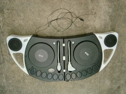
Click to zoom
Application Details
- Equipment Class
- DXX - Part 15 Low Power Communication Device Transmitter
- Date of Grant
- Apr 19, 2001
- Application Purpose
- Original Equipment
- Date of Application
- Apr 19, 2001
- Equipment Note
- DJ Mixer AM Band Transmitter
- Frequency Range
- 1.61000000 - 1.61000000
- Company
- MGA Entertainment (HK) Ltd.
- Country
- Hong Kong
Documents & Files
Document Text
Text extracted from the exhibit documents filed with the FCC. Open a document above to read the original.
External Photos
FCC ID: LU9243632 PHOTOGRAPH OF THE PRODUCT FRONT VIEW OF THE PRODUCT REAR VIEW OF THE PRODUCT
ID Label/Location Info
FCC ID LABEL
ID Label/Location Info
FCC ID: LU9243632 LABEL LOCATION BOTTOM VIEW OF THE DEVICE WITH FCC ID LABEL
Internal Photos
FCC ID: LU9243632 PHOTOGRAPH OF THE PRODUCT INNER CIRCUIT TOP VIEW INNER CIRCUIT BOTTOM VIEW
Operational Description
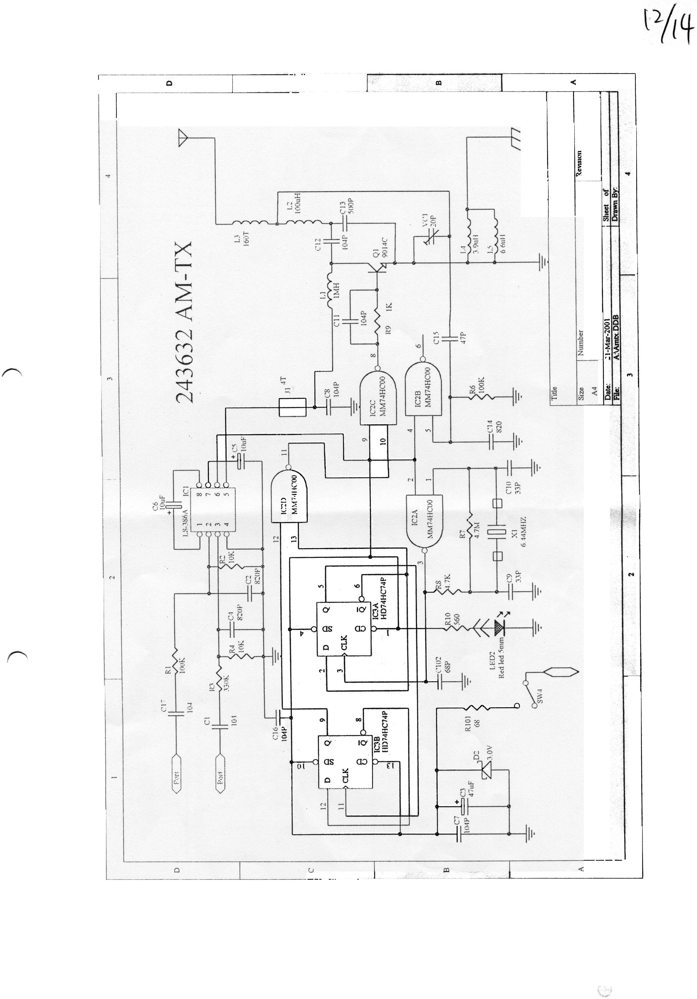
FCC ID: LU9243632 Circuit Description The 1.61MHz crystal oscillator drives the base of Q1 the final/buffer amplifier. The modulation provided by IC. The output of Q1 has the matching network consisting of L3 and C12 that limit the harmonic content and effect the proper coupling of the antenna to the output stage. Antenna, Ground and Power Source The antenna consists of a 2cm long wire. There is no external ground connection. The ground is only that of the printed circuit board. Electric current is supplied by a 6 Volt (“C” size battery x 4) primary battery
Test Report
Date: 2001-03-31 TEST REPORT Page 1 of 7 No.: HM104129 Law Man KitSteven TsangPatrick Wong Testing EngineerVerify byPatrick Wong for Managing Director APPLICANT: (CODE: MGE001) MGA ENTERTAINMENT (HK) LTD. Room 1001 Empire Centre, 68 Mody Road, T.S.T. East, Kowloon, Hong Kong. DATE OF SAMPLE(S) RECEIVED: 2001-02-17 SUBMITTED SAMPLE(S): 1 sample DATE OF TESTING: 2001-03-21 DESCRIPTION OF SAMPLE(S): A sample of product said to be: Product:ONE MAN JAM - DJ MIXER Manufacturer:MILLION INDUSTRIAL LTD. Model Number:243632 Brand Name:N/A Rating: 6V d.c. ("C” size battery × 4) Origin:CHINA INVESTIGATIONS REQUESTED: Measurement to the relevant clauses of F.C.C. Rules and Regulations 15.203 an intentional radiator shall be designed to ensure that no antenna other than that furnished by the responsible party shall be used with the device. The use of a permanently attached antenna or of an antenna that uses a unique coupling to the intentional radiator shall be considered sufficient to comply with the provisions of Part 15C. The manufacturer may design the unit so that the user can replace a broken antenna, but the use of a standard antenna jack or electrical connector is prohibited. This requirement does not apply to carrier current devices or to devices operated under the provisions of section 15.211, 15.213, 15.217, 15.219 or 15.221. Further, this requirement does not apply to intentional radiators that must be professionally installed, such as perimeter protection systems and some field disturbance sensors, or to other intentional radiators, which, in accordance with section 15.31(d), must be measured at the installation site. However, the installer shall be responsible for ensuring that the proper antenna is employed so that the limits in this part are not exceeded. RESULT/ REMARK: Please see attached sheet(s). CONCLUSION: From the measurement data obtained, the tested sample (sample 1 of 1) was considered to have COMPLIED with the clause 15.219 of Federal Communications Commission Rules and Regulations Part 15. TEST EQUIPMENT AUDIT: Please see Appendix A Date: 2001-03-31 TEST REPORT Page 2 of 7 No.: HM104129 T E S T S U M M A R Y *** INTENTIONAL RADIATOR *** (1) Measurement of emission of RF energy on the carrier frequency...........Satisfactory (2) Antenna Length........................................................................................Satisfactory (3) Measurement of product emission...........................................................Satisfactory (4) Measurement of line-conducted voltage onto AC power line.................Not applicable *** UNINTENTIONAL RADIATOR *** (1) Measurement of product emission The spectrum was checked from 30MHz (lowest frequency for which a radiated emission limit is specified) to 1000MHz. All emissions were too low to be measurable and they were all more than 20dB below the permitted limit. (2) Measurement of line-conducted voltage onto AC power line.................Not applicable T E S T D A T A Please refer to the attached result sheets. Date: 2001-03-31 TEST REPORT Page 3 of 7 No.: HM104129 *** INTENTIONAL RADIATOR *** (1) Measurement of Radiated Interference TEST REFERENCE:FCC CFR47, Part 15 Subpart C Section 15.219(510-1705KHz) TEST CONDITION:Normal TEST DATE:2001-03-21 Section 15.219 operation in the band 510-1705KHz The total input power to final radio frequency stage (exclusive of filament or heater power) shall not exceed 100 milliwatts. Test Procedures The EUT was modified to measure both the current and voltage delivered to the final radio frequency stage. Test Result Measured final radio frequency stage voltage = 3.32 volts Measured final radio frequency stage current = 6.28 milliamps Calculated final radio frequency stage power = 20.85 milliwatts. Date: 2001-03-31 TEST REPORT Page 4 of 7 No.: HM104129 *** INTENTIONAL RADIATOR *** (2) Antenna Length TEST REFERENCE:FCC CFR47, Part 15 Subpart C Section 15.219(510-1705KHz) TEST CONDITION:Normal TEST DATE:2001-03-21 Section 15.219 operation in the band 510-1705KHz The total length of the transmission line antenna and ground lead (if used) shall not exceed 3 meters. Result The antenna is 2 meters and the there is a ground lead is 0.9 meter. Date: 2001-03-31 TEST REPORT Page 5 of 7 No.: HM104129 *** INTENTIONAL RADIATOR *** TEST REFERENCE:FCC CFR47, Part 15 Subpart C Section 15.219(510-1705KHz) TEST CONDITION:Normal TEST DATE:2001-03-21 (3) PRODUCT EMISSIONS ================================================================== EmissionMeter FCC LimitDelta to Limit FrequencyReading MHzdB( μ V/m)dB( μ V/m)dB 3.2233.135.4-2.3 4.8316.635.4-18.8 19.3234.235.4-1.2 ================================================================== Calculation of the limit The maximized fundamental emission from the EUT at 1610KHz was measured to be 55.4dBμV/m, therefore the limit for all spurious emissions is 35.4. Date: 2001-03-31 TEST REPORT Page 6 of 7 No.: HM104129 NOTES FOR THE RADIATION MEASUREMENT (1) Test site facility: Open field test site located at Taipo (Hong Kong) with a metal ground plane on filed with the FCC pursuant to section 2.948 of the FCC Rules. (2) Distance between the EUT and measuring antenna: 3 meters. (3) Measuring antenna: All emissions below 510KHz or above 1705 shall be attenuated at least 20dB below the level of the unmodulated carrier. Determination of compliance with the 20dB attenuation specification may be based on measurements at the intentional radiator‘s antenna output terminal unless the intentional radiator uses a permanently attached antenna, which case compliance shall be demonstrated by measuring the radiated emissions. (4) Frequency range scanned: The frequency range from 510KHz to 1705KHz had been searched. Readings of the highest emissions relating to the limit were reported as above. (5) Arrangement of EUT: During the test, the sample was operated at rated supply voltage and arranged for maximum emissions. (6) Measuring Procedure: The procedure used was based on ANSI STAN…
Text truncated - open the document above for the full version.
Test Report
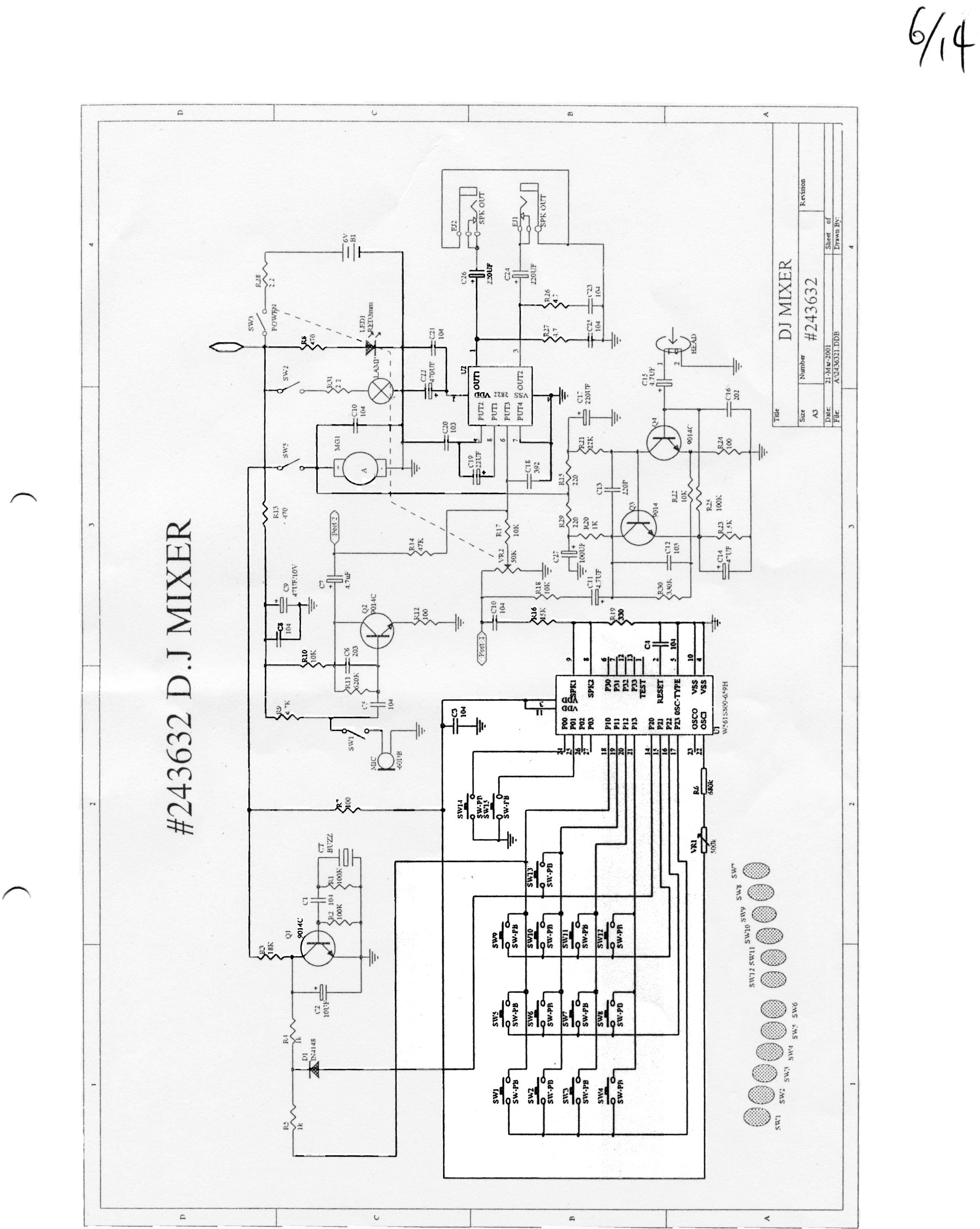
Chris Harvey From:Chris Harvey Sent:Wednesday, April 18, 2001 9:02 AM To:'Alice Wong'; TCB INFO Cc:Chris Harvey; Marianne Bosley; Greg Czumak; EED - Choy, Kitty Subject:RE: MGA Entertainment FCC ID:LU9243632 Request for Technical MET#10810 Alice, I did not receive a response to my question number 6 about the schematics. Please provide a clearer/legible schematic diagram. Your description of the antenna manipulation did not include any indication that the antenna is rotated throughout the vertical axis as well as the polarity. Please reference ANSI C63.4:1992 for this procedure and ensure that you have manipulated the antenna correctly. Also, please note that since this device is also a digital device, is class B and does not connect to a computer, it is required to comply with the Class B Verification Technical and Administrative requirements. Please be sure that you are providing your customer with guidance on the requirements of FCC Rule Parts 15.21 and 15.105 for information required in the Users Manual. You do not need to provide this information to MET since I am not reviewing the application for Digital Device Compliance, and that they are provided with documentation about the Compliance with the Technical requirements (i.e. radiated limits 30MHz to 1GHz). As soon as I can review the new schematics, this application can be granted. Best regards, Chris Harvey Chris Harvey EMC Lab Director MET Laboratories, Inc. 1-800-638-6057 [email protected] www.metlabs.com -----Origina l Message----- From:Alice Wong [SMTP:[email protected]] Sent:Wednesday, April 18, 2001 5:35 AM To:[email protected] Cc:[email protected]; [email protected]; Greg C zumak; EED - Choy, Kitty Subject:Re: MGA Entertainment FCC ID:LU9243632 Request for Technical Dear Chris, Thank you for your e-mail. FCC ID: LU9243632 MGA Entertainment (HK) Ltd. 1) Active loop antenna is used model: 6502 s/n: 1189-2424, Manufacturer: EMCO. Preview test are performed to determine the "worse case" mode of operation, with the EUT operating in worst case, emissions from the unit are maximized by adjusting the polarization and height of the receive antenna and rotating the EUT on the turntable. Manipulating the system cable also maximizes EUT emission. 2) For the section 12.219, frequency range of measurement is between 0.1MHz and 30MHz. [Chris Harvey] I will assume t hat this was supposed to be 15.219. 3) The EUT antenna is 2 meter long signal wire cable (D#1mm) connect to PCB and 0.9 meter long signal wire cable connect to ground. 4) & 5) Please see attached file for revised user manual. 6) The EUT is a digital device and compliance FCC CFR 47 15.109, However no emissions detected within 20dB of the FCC limits, so no indicate the test result on the report. 7) The EUT is operated by internal battery power only, therefore power line conducted emissions was deemed unnecessary and need customer correct the users manual. Have a nice day Best Regards Alice ----- Original Message ----- From: "Ms. Shirley Tsang" <[email protected]> To: "Alice Wong" <[email protected]> Sent: Tuesday, April 17, 2001 8:57 AM Subject: Fw: MGA Entertainment FCC ID:LU9243632 Request for Technical > > ----- Original Message ----- > From: TCB INFO <[email protected]> > To: <[email protected]> > Cc: <[email protected]>; Marianne Bosley <[email protected]>; Greg > Czumak <[email protected]> > Sent: 2001/mm/17 01:26 > Subject: MGA Entertainment FCC ID:LU9243632 Request for Technical > > > > Alice, I have reviewed the MGA Entertainment Application for FCC ID > > LU9243632 (MET#10810) and have discovered the following items that need to > > be cleared before the application can be granted: > > > > 1) the Antennas for measurement do not include antennas that can measure > > Radiated signals below 25MHz. Please indicate the antenna used for > > measurement and an indication if this antenna is a loop or Rod antenna per > > FCC requirements. Also, please provide the antenna manipulation procedure > > below 30MHz. > > > > 2) Please provide the frequency range of measurements per 15.33 (range > > specified does not seem correct). > > > > 3) The EUT Antenna is specified as 2 meters in the report and 2cm per the > > circ description document. Please clarify. > > > > 4) FCC 15.203 requires that devices that operate under FCC 15.219 are > > provided with guidance to the user about the use of the proper antenna for > > compliance. THere apperas to be no such guidance in the users manual. > > Please correct this discrepancy. > > > > 5) The setup photo shows the EUT antenna as being laid across the > > measurement table, however the Users Manual indicates that the antenna > > should be hung upright to provide the "brightest" signal. Please correct > > this discrepancy. > > > > 6) Please provide clearer schematic Diagrams. The Schematics provided are > > not legible and raise some questions. It appears as though this device > may > > also be a Digital Device (can not determine due to unclear schematics) > which > > may require compliance with FCC Subpart B for a Digital Device Class B > > Verification. > > > > 7) Please clarify the Power to the EUT. If this allows provisions for AC > > connection or an AC/DC adaptor, then measurements for Conducted Emissions > > per FCC 15.207 are required. > > > > Best regards, > > > > Chris Harvey > > [email protected] << File: Manual.pdf >>
Test Setup Photos
FCC ID: LU9243632 TEST SET UP PHOTOGRAPH OF THE PRODUCT Measurement of Radiated Emission Test Set up FCC ID: LU9243632 Measurement of Line-Conducted Voltage Test Set up
Contact Information
Applicant
Julian Chung(QA Director)
Test Firm
Hong Kong Standards & Testing Cen.Wilson Wong
Technical Specifications
| # | Rule Parts | Frequency Range | Power Output |
|---|---|---|---|
| 1 | 15C | 1.61 MHz - 1.61 MHz | - |
Other Applications from MGA Entertainment (HK) Ltd.
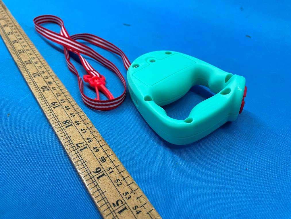
LU9657719TX
Feb 24, 2022Rescue Tales Walk N Wiggle Daisy
Equipment Class
DXX - Part 15 Low Power Communication Device Transmitter
LU9657566
Jul 29, 2021Tobi 2 Interactive Karaoke Machine
Equipment Class
DSS - Part 15 Spread Spectrum Transmitter
LU9654824
Jun 06, 2021My Real Jam Drum Set
Equipment Class
DXX - Part 15 Low Power Communication Device Transmitter
LU9654794
Jun 06, 2021My Real Jam-Acoustic Guitar
Equipment Class
DXX - Part 15 Low Power Communication Device Transmitter
LU9654800
Jun 06, 2021My Real Jam-Electric Guitar
Equipment Class
DXX - Part 15 Low Power Communication Device Transmitter