LU9305132Wireless Telephone
MGA Entertainment (HK) Ltd.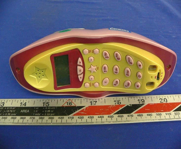
Click to zoom
Application Details
- Equipment Class
- DXX - Part 15 Low Power Communication Device Transmitter
- Date of Grant
- Apr 25, 2005
- Application Purpose
- Original Equipment
- Date of Application
- Apr 25, 2005
- Equipment Note
- Wireless Telephone
- Frequency Range
- 2472.00000000 - 2475.90000000
- Company
- MGA Entertainment (HK) Ltd.
- Country
- Hong Kong
Documents & Files
Document Text
Text extracted from the exhibit documents filed with the FCC. Open a document above to read the original.
Users Manual
2.4GHZ CORDLESS TELEPHONE WITH CALL WAITING CALLER ID INSTALLATION AND OPERATING GUIDE IMPORTANT: To receive Caller ID information on incoming telephone calls, you must subscribe to the Caller ID service provided by your local telephone company; there is a fee for this service and it may not be available in all areas. TM NTP-6323 TABLE OF CONTENTS 1 Important Safety Instructions ....................2 FCC Regulations ....................................3-4 Battery Cautionary Instructions ............5 NTP-6323 Parts Checklist ......................6 Location of Controls and Features.......7-10 Handset ..............................................7-8 Base..................................................9-10 Choosing a Location .................................11 Telephone Setup.................................12-14 Connecting the Base...........................12 1 Tone/Pulse Switch...............................13 Handset Volume ..................................13 Battery Installation...................................14 Battery Duration ...................................1 4 When the Battery Needs Charging ......14 When to Purchase a New Battery Pack........................................14 Basic Displays.........................................15 Basic Operation..................................16-17 Making Calls.........................................16 Receiving Calls.....................................1 6 Redialing..............................................17 Addit ional Options..............................17 Caller ID............................................30-34 When You Receive a Call.....................3 0 Viewing the Caller ID List....................30 Caller ID Displays................................31 Caller ID with Call Waiting Service .......32 Storing Caller ID Records....................32 Deleting Caller ID Records ..................33 Returning Caller ID Calls .....................34 Message Waiting ...................................35 Using One-Touch Voice Mail Dialing ....35 Other Features ......................................36 Using the Handset Finder (PAGE)......36 Channel Changing ...............................36 Care and Maintenance............................37 Troubleshooting.......................................38 Glossary ...................................................39 Settings.................................................18-24 Handset Settings...............................18-19 Changing the Language.........................19 Muting the First Ring On or Off..............20 Setting the Time and Date......................20 Setting the Ringer Level.........................21 Adjusting the Contrast............................21 Changing the Flash Time......................22 Changing the Pause Time.....................23 Programming One-Touch Voice Mail Dialing..................................23 Deleting Message Waiting Indication...............................................24 Speed Dialing..............................25-29 Storing Phone Numbers..................25 Letter Table....................................26 Viewing the Phone Book................ .26 Making Calls From the Phone Book..............................................27 Editing a Stored Number.................27 Deleting a Stored Number...............28 Deleting All Stored numbers............28 Preferred Calls...............................29 Blocked Calls.................................29 Setting the Area Code...........................22 ...... ..... Warranty...................................................40 MGA 1 Year Limited Warranty This limited warranty sets forth all MGA responsibilities regarding your product. There are no other expressed or implied warranties from MGA Warranty Service Provided If you purchased the telephone new from a retail vendor, MGA warrants the telephone against defects in material and workmanship for a period of one(1) year from the original date of purchase. This warranty is in lieu of all other expressed warranties. This warranty begins when you purchase the telephone and continues for one (1) year unless you sell or rent the telephone, in which event the warranty stops. MGA disclaims any implied warranty, including the warranty of merchantability and the warranty of fitness for a particular purpose, as of the date of one year from your original purchase of the telephone. MGA assumes no responsibility for any special, incidental, or consequential damages. This warranty gives you specific legal rights and you may have other rights, which vary from state to state. Some states do not allow the exclusion or limitation of special, incidental or consequential damages or limitations on how long a warranty lasts, so the above exclusion and limitation may not apply to you. Warranty service not provided This warranty does not cover damage resulting from accident, misuse, abuse, improper installation or operation, lack of reasonable care, unauthorized modification, the affixing of any attachment not provided by MGA with the telephone and or loss of parts. This warranty is voided in the event any unauthorized person opens, alters or repairs the telephone. All MGA products being returned for repair must be suitably packaged. Telephone companies use different types of equipment and offer various types of services to customers. MGA does not warrant that this telephone is compatible with the type of equipment of any particular telephone company or the services provided by it. What to do for warranty service During the first thirty (30) days, a defective product is eligible for over the counter exchange at the retailer from whom it was purchased. After thirty (30) days the defective product should be returned to the authorized service center. 40 Warranty SAVE THESE INSTRUCTIONS This symbol is to alert you to important operating or servicing instructions that may appear in the user's manual. Always follow basic safety precautions when using t…
Text truncated - open the document above for the full version.
Block Diagram
RX DATA APPROVAL CHECK PREPARE Base Block Diagram RF Module Expander Data Comparator CPU Tele Speech Tel Jack Carrier Detcct RX Power Control Compressor Audio Input TX DATA Reset Circurt Line Detect Charge Detect Audio Output Line Control FSK 5V DC 5V5V PLL Data TX Power Control RX DATA APPROVAL CHECK PREPARE Hand Block Diagram RF Module Expander Data Compartor CPU Carrier Detect RX Power Control PLL Data TX Power Control Compressor Audio Input Reset key Audio Output Amp output SP mic LCD Display Battery Low Detect Charge Detect TX DATA 3.8V Battery APPROVAL CHECK PREPARE Base RF Module Block Diagram RF Receiver BPF 2473.90±2MHz RF Transmitter BPF 2404.950±2MHz Ant 2472.000~2475.950M HzLNA Pre- AMP 455KHz Mix2 IF1BPF LIM AMP DEM Audio OutputCarrier Detect 827.567~828.867MHz/3 RX-VCO Dual Frequency Synthesizer 2403.050~2406.950MH zPA 801.017~802.317MHz/3 TX-VCO MOD Audio Input ×3 ×3 PLL DATA 10.7MHz Mix1 11.150MHz TX Power RX Power APPROVAL CHECK PREPARE Hand RF Module Block Diagram RF Receiver BPF 2404.950±2MHz RF Transmitter BPF 2473.900±2MHz Ant 2402.950~2406.950M HzLNA Pre- AMP 455KHz Mix2 IF1BPF LIM AMP DEM Audio OutputCarrier Detect 797.450~798.750MHz/3 RX-VCO Dual Frequency Synthesizer 2472.000~2475.900MH zPA 824.000~825.300MHz/3 TX-VCO MOD Audio Input Detector ×3 ×3 PLL DATA 10.7MHz Mix1 11.150MHz TX Power Rx Power
External Photos
EXHIBIT C - EUT EXTERNAL PHOTOGRAPHS Base – Chassis Front View Base – Chassis Rear View Base – Chassis Side View Handset – Chassis Top View Handset – Chassis Side View Handset – Chassis Rear View Power Supply
ID Label/Location Info
EXHIBIT A - FCC ID LABEL INFORMATION Proposed FCC ID Label Specifications: Text is black or white in color and is left justified. Labels are silk- screened and shall be “permanently affixed” at a conspicuous location on the EUT. Proposed Label Location on EUT Bottom view of EUT / Proposed Label location (Base) (Handset) FCC ID: LU9305132 This device complies with Part 15 of the FCC Rules. Operation is subject to the following two conditions: (1) this device may not cause harmful interference, and (2) this device must accept any interference received, includin g interference that may cause undesired
Internal Photos
EXHIBIT C - EUT INTERNAL PHOTOGRAPHS Base EUT 1 – Component View Base EUT 1 – Solder View Base EUT 1 – Antenna Close View Key / LED Boards – Solder View Base EUT 2 – Component View Base EUT 2 – Solder View Base EUT 3 – Component View Base EUT 3 – Solder View Handset – Chassis Cover Off View Handset EUT 1 – Component View Handset EUT 1 – Solder View Handset EUT 2 – Component View Handset EUT 2 – Solder View Handset – Antenna Close View
Operational Description
CIRCUIT DESCRIPTION 1 Base a. RF Transmitter Section – RF Board The compressed audio signal (RF module pin 10) is modulated through the varactor diode VD201. These components, i.e. VD201, C216, L201, Q203 and the external components of Q203 compose the voltage controlled oscillator circuit for the transmitter part. This circuit generates the TX VCO frequency. A portion of this signal is fed back to the PLL IC (SIT8825B)’s pin1 (FIN1) for phase comparison. Once the phase of oscillation stabilized, the PLL circuit generates the error voltage necessary for the VCO to oscillate at the desired transmitter’s RF frequency. The VCO circuit impedance is matched with the succeeding circuit through the transistor Q202 that also acts as the buffer amplifier. The RF amplifier Q201 boosts the signal for transmission. This amplified RF signal is trimmed to the desired frequency band by F2 (BPF2403) so as not to interfere with the receiver circuit. The transmitter RF signal is then propagated through the antenna. b. RF Receiver Section – RF Board The Base Unit antenna receives RF signal. The Band Pass Filter F1 (BPF2475) trims the signal to the desirable frequency band. Transistor Q101 $ Q104 is a low noise amplifier that boosts the RF signal to a specific level for mixing. PLL U2 (SIT8825B) is used as a Universal Phase Lock Loop circuit. The frequency from the Voltage Controlled Oscillator (VCO) VD101, L102 and Q103, is fed back to the PLL IC through pin 16 (FIN2) for phase comparison. During channel scanning or turning the unit on, once the phase of oscillation stabilized (locked), the PLL circuit generates the first local oscillator frequency for down-converting the received RF signal into the first IF frequency 10.7Mhz. This process is accomplished through the IF mixer circuit Q104. Q104 is used for matching the impedance of the mixer circuit with the succeeding circuits. The resulting IF signal is kept constant by the IF Filter F3 to 10.7MHz which is then mixed with the second local oscillator frequency 11.150MHz (derived from X1 & VC1) to produced a much lower IF frequency. This lower IF frequency if further filtered by IF Filter FL4 to produce a more stable signal of 10.7Mz. Quadrature signal detection is accomplished internally by the Narrow-band Detector U1 (SIT8531) with the IF coil T1. The recovered audio frequency can be taken from U1 audio output pin7. c. Transmitter Audio Section – Main Board The Audio Frequency signal from the telephone line that is through Q7/9, R23,R4, R9,C7,R90, U4-8, U4-1, C54, VR1, etc is compressed through the compressor part of U4 to minimize the transmission noise. The degree of compression depends on the external RC combinations. AGC is also utilized by U4 to avoid shock noise caused by abrupt change of audio levels. The compressed audio is filtered and amplified for better acoustical performance. d. Receiver Audio Section – Main Board The compressed Audio Frequency signal from the RF module (pin3) is passed through passive RC filters for acoustic compliance. The filtered audio is then fed to the Compander U4 (pin16 and pin17) for expansion thus retrieving the original Audio signal with noise filtered out. Q2 is used as buffer circuit. Bridge rectifier D1,D2,D6,D7 isolates the high-voltage telephone line to the rest of the circuit. 2 Handset a. RF Transmitter Section – RF Board Refer to portion 1.b for this section. All circuit performance is the same except that Band Pass Filter BPF2403 is changed to BPF2475 for the handset transmission. b. RF Receiver Section – RF Board Refer to portion 1.b for this section. All circuit performance is the same except that Band Pass Filter BPF2475 is changed to BPF2403 for the handset transmission. c. Transmitter Audio Section – Main Board Audio Frequency signal from the handset or from the headset microphone is compressed through the compressor part of IC1 to minimize the transmission noise. The degree of compression depends on the external RC combinations. AGC is also utilized by IC1 to avoid shock noise caused by abrupt change of audio levels. The compressed audio is filtered and amplified for better acoustical performance. Q3 is a switching transistor that controls the power supply for the TX RF part. d. Receiver Audio Section – Main Board The compressed Audio Frequency signal from the RF module is passed through passive RC filters for acoustic compliance. The filtered audio is then fed to the Compander IC1 for expansion thus retrieving the original audio signal with noise filtered out. Q2 & Q10 act as audio amplifier to sufficiently drive the handset speaker. Q7 and Q8 are switching transistors that control the power supply for the RF part, the Compander part and the AF amplifier respectively. An earphone jack is provided for an optional headset unit for hands free conversation on the handset. 3 OTHERS (Handset): a. Charging and Reset Controls Recharging the handset battery is accomplished by putting the handset on the cradle. Q4 and its external components are the reset circuit. R24 and R25 detect this action and send a command to the CPU (IC2 pin24) for proper exchange of security code. b. Ring Detection When the handset receives the ring command from the base unit, the CPU will send buzzer signal to the ringer amplifier Q5 and Q6 that drives the Buzzer. 4 OTHERS (Base): a. Hook Switching and Dialing The transistor Q1 that is controlled by the U1 (pin21) accomplishes the hook switching and the pulse dialing function. The DTMF signal from the U1(pin38) is amplified by Q2. b. Over-voltage Protection Fuse 1 and varistor ZR1 act as high current and high voltage protectors for the telephone line interface. In case of presence of voltage surge across the telephone line, Fuse 1 decreases its resistance and dumps the line voltage to a safe level. Fuse1 opens when excessive current is present on the line thus protecting both the user and the line interface. c. Battery Charging & Code Setting Battery charging commences when Q6 dete…
Text truncated - open the document above for the full version.
Schematics
RF2400WB S1T8825B.SCH-1 - Thu Feb 17 19:52:38 2005 RF2400WH S1T8531B.SCH-1 - Tue Mar 08 15:37:39 2005 6323BM(050221.sch-1 - Thu Mar 10 18:02:34 2005 6323BM(050221.sch-2 - Thu Mar 10 18:02:44 2005
Test Report
Note: The test report is specially limited to the above company and the product model only. It may not be duplicated without prior written consent of Bay Area Compliance Laboratory Corporation. This report must not be used by the client to claim product certification, approval, or endorsement by NVLAP, NIST or any agency of the US Government. FCC PART 15.249 EMI MEASUREMENT AND TEST REPORT For MGA Entertainment (H.K.) Ltd. 9 th Floor,Tower 6,The Gateway,Harbour City,9 Canton Road,Tsimshatsui,Kowloon,Hong Kong FCC ID: LU9305132 This Report Concerns: Original Report Equipment Type: Wireless Telephone Test Engineer: Jerry Wang/ Report No.: R0503215 Report Date: 2005-03-28 Reviewed By: Hang Tan/ Prepared By: Bay Area Compliance Laboratory Corporation 230 Commercial Street Sunnyvale, CA 94085 Tel (408) 732-9162 Fax (408) 732-9164 MGA Entertainment (H.K.) Ltd. FCC ID: LU9305132 Report # R0503215Rpt-aRpt Page 2 of 21 FCC Part 15.249 Test Report TABLE OF CONTENTS GENERAL INFORMATION.......................................................................................................................................3 PRODUCT DESCRIPTION FOR EQUIPMENT UNDER TEST (EUT) ....................................................................................3 OBJECTIVE...................................................................................................................................................................3 RELATED SUBMITTAL(S)/GRANT(S).............................................................................................................................3 TEST METHODOLOGY..................................................................................................................................................3 TEST FACILITY.............................................................................................................................................................3 SYSTEM TEST CONFIGURATION ..........................................................................................................................5 JUSTIFICATION.............................................................................................................................................................5 SCHEMATICS AND BLOCK DIAGRAM............................................................................................................................5 EQUIPMENT MODIFICATIONS.......................................................................................................................................5 POWER SUPPLY...........................................................................................................................................................5 LOCAL SUPPORT EQUIPMENT.......................................................................................................................................5 PRINTED CIRCUIT BOARDS IN EUT ..............................................................................................................................5 INTERFACE PORTS AND CABLING.................................................................................................................................5 SUMMARY OF TEST RESULTS ...............................................................................................................................7 §15.203 - ANTENNA REQUIREMENT......................................................................................................................8 STANDARD APPLICABLE..............................................................................................................................................8 ANTENNA CONNECTED CONSTRUCTION......................................................................................................................8 § 15.207 (A) - CONDUCTED EMISSIONS TEST DATA .........................................................................................9 MEASUREMENT UNCERTAINTY....................................................................................................................................9 EUT SETUP..................................................................................................................................................................9 RECEIVER SETUP..........................................................................................................................................................9 TEST EQUIPMENT LIST AND DETAILS...........................................................................................................................9 TEST PROCEDURE........................................................................................................................................................9 ENVIRONMENTAL CONDITIONS....................................................................................................................................9 SUMMARY OF TEST RESULTS.....................................................................................................................................10 CONDUCTED EMISSIONS TEST DATA.........................................................................................................................10 PLOT OF CONDUCTED EMISSIONS TEST DATA...........................................................................................................10 §15.205 & §15.249 (A) (D) - RADIATED EMISSION DATA .................................................................................13 APPLICABLE STANDARD............................................................................................................................................13 MEASUREMENT UNCERTAINTY..................................................................................................................................13 EUT SETUP........................................................................................................................................…
Text truncated - open the document above for the full version.
Test Setup Photos
EXHIBIT B - TEST SETUP PHOTOGRAPHS Conducted Emission – Front View Conducted Emission – Rear View Base Radiated Emission – Front View Base Radiated Emission – Rear View Handset Radiated Emission – Front View Handset Radiated Emission – Rear View
Contact Information
Applicant
Julian Chung(QA Director)
Test Firm
Bay Area Compliance LaboratoryJohn Chan
Technical Specifications
| # | Rule Parts | Frequency Range | Power Output |
|---|---|---|---|
| 2 | 15C | 2.47 GHz - 2.48 GHz | - |
Other Applications from MGA Entertainment (HK) Ltd.
LU9657719TX
Feb 24, 2022Rescue Tales Walk N Wiggle Daisy
Equipment Class
DXX - Part 15 Low Power Communication Device Transmitter
LU9657566
Jul 29, 2021Tobi 2 Interactive Karaoke Machine
Equipment Class
DSS - Part 15 Spread Spectrum Transmitter
LU9654824
Jun 06, 2021My Real Jam Drum Set
Equipment Class
DXX - Part 15 Low Power Communication Device Transmitter
LU9654794
Jun 06, 2021My Real Jam-Acoustic Guitar
Equipment Class
DXX - Part 15 Low Power Communication Device Transmitter
LU9654800
Jun 06, 2021My Real Jam-Electric Guitar
Equipment Class
DXX - Part 15 Low Power Communication Device Transmitter