LZ6ALPHA506SERIESIndustrial Remote Control System
Fomotech International Corp.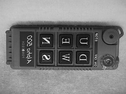
Click to zoom
Application Details
- Equipment Class
- DSC - Part 15 Security/Remote Control Transmitter
- Date of Grant
- Mar 18, 2001
- Application Purpose
- Original Equipment
- Date of Application
- Feb 04, 2001
- Equipment Note
- Industrial Remote Control System
- Frequency Range
- 301.40000000 - 301.40000000
- Company
- Fomotech International Corp.
- Country
- Taiwan
Documents & Files
Document Text
Text extracted from the exhibit documents filed with the FCC. Open a document above to read the original.
Users Manual
1 TABLE OF CONTENTS Page 1. INTRODUCTION ....................................................................................................... 2 2. SAFETY INSTRUCTION ............................................................................................. 3 3. PUSHBUTTON CONFIGURATION 3.1 Alpha 500/520 ....................................................................................................... 4 3.2 Alpha 540/560 ....................................................................................................... 5 3.3 Alpha 540T/560T "Select" Settings ................................................................... 6 3.4 FCC ID Labels and Numbers ............................................................................... 6 4. TRANSMITTER OUTLINE 4.1 Alpha 500/520 ....................................................................................................... 7 4.2 Alpha 540/560 ....................................................................................................... 8 5. RECEIVER OUTLINE 5.1 Alpha 500/520/540/560 ......................................................................................... 9 5.2 Alpha 500/520 Internal Assembly ......................................................................... 10 5.3 Alpha 540/560 Internal Assembly ......................................................................... 11 6. OUTPUT CONTACT DIAGRAM 6.1 Alpha 500/520 Wiring Diagrams .......................................................................... 12 6.2 Alpha 540 Wiring Diagrams ................................................................................. 13 6.3 Alpha 560 Wiring Diagrams ................................................................................. 14 7. SYSTEM SETTING CONFIGURATION ................................................................... 15~16 8. RECEIVER INSTALLATION 8.1 Preparation For Installation ................................................................................... 17 8.2 Step By Step Installation ....................................................................................... 17 8.3 System Testing ....................................................................................................... 18 9. TRANSMITTER OPERATION ................................................................................... 19-20 10. TROUBLE SHOOTING ............................................................................................... 21 11. SYSTEM SPECIFICATION ......................................................................................... 22-23 12. PARTS LIST ................................................................................................................. 24 2 1. INTRODUCTION The Alpha 500 series are highly reliable industrial remote control systems. The versatile features of the Alpha 500 series permit its use in many different remote control applications. They can be used to control cranes, hoists, trolleys, mining equipment, building construction equipment, automatic control systems, and many others. The Alpha 500 series radio control system incorporates numerous redundant safety circuits that guaranty maximum security and ensure the system is resistant to outside interference. The major features of the Alpha 500 series are as follow: * The system uses advanced microprocessors which utilizes highly evolved software that have redundant error checking and correcting capabilities to ensure 100 % error-free transmission, decoding, and control of the output relays. These highly evolved software include CRC (Cyclic Redundancy Check codes) and Hamming Codes. * To insure maximum operating safety, the Alpha 500 series incorporate many safety features. Some of these safety features include receiver self-diagnosing, transmitter pushbutton self-diagnosing, transmitter low voltage detection/warning, transmitter/receiver auto shutdown after 1 minute of transmitter low voltage warning, and receiver MAIN deactivation during transmitter non-usage (programmable from 0~30 minutes). * The encoder/decoder system utilizes advanced microprocessor. The availability of 32,768 sets of unique ID codes will ensure that only commands from the matching control transmitter can be carried out without any interference from other radio systems. A special programmable integrated circuit is used to insure the unit can not simultaneously command conflicting movements. * Full SMT design for system stability. The Alpha 500 series radio control system consists of a transmitter handheld, a receiver unit, and a six-foot (2-meter) output cable. The transmitter casing is molded using an industrial strength composite material which is impervious to dust, water, oil, acids, alkaline, heat, sunlight, and as well as being resistant to deformation due to long term use in harsh environments. The pushbuttons are also constructed from industrial strength composite material with a minimum of up to one million cycles. For power saving, the transmitter unit uses special high efficiency power saving circuits that requires only two “AA” alkaline batteries (UM-3). 3 2. SAFETY INSTRUCTION The Alpha 500 systems are relatively simple to use. However, it is very important to observe the proper safety procedures during operation. When use properly the Alpha 500 systems will enhance productivity and efficiency in the workplace. The following instructions should be strictly followed: 1. Make a daily check of the transmitter casing and pushbuttons. Should it appear that anything could inhibit the proper operation of the transmitter unit, it should be immediately removed from service. 2. The transmitter voltage should be checked on a daily basis. If the voltage is low, the two "AA" alkaline batteries should be replaced. 3. The emergency stop pushbutton (EMS) should be checked at the beginning of each shift to ensure they are in the proper working order. 4. In the event of an emergency, activate the emergency…
Text truncated - open the document above for the full version.
ID Label/Location Info
FCC ID: LZ6ALPHA506SERIES FOMOTECH INTERNATIONAL CORP. This Device complies with Part 15 of the FCC Rules. Operation is subject to the following two conditions: (1) this device may not cause harmful interference and (2) this device must accept any interference received, including interference that may cause undesired operation. (Alpha 560 Model)
ID Label/Location Info
Label Location
Operational Description
1 TABLE OF CONTENTS Page 1. INTRODUCTION ....................................................................................................... 2 2. SAFETY INSTRUCTION ............................................................................................. 3 3. PUSHBUTTON CONFIGURATION 3.1 Alpha 500/520 ....................................................................................................... 4 3.2 Alpha 540/560 ....................................................................................................... 5 3.3 Alpha 540T/560T "Select" Settings ................................................................... 6 3.4 FCC ID Labels and Numbers ............................................................................... 6 4. TRANSMITTER OUTLINE 4.1 Alpha 500/520 ....................................................................................................... 7 4.2 Alpha 540/560 ....................................................................................................... 8 5. RECEIVER OUTLINE 5.1 Alpha 500/520/540/560 ......................................................................................... 9 5.2 Alpha 500/520 Internal Assembly ......................................................................... 10 5.3 Alpha 540/560 Internal Assembly ......................................................................... 11 6. OUTPUT CONTACT DIAGRAM 6.1 Alpha 500/520 Wiring Diagrams .......................................................................... 12 6.2 Alpha 540 Wiring Diagrams ................................................................................. 13 6.3 Alpha 560 Wiring Diagrams ................................................................................. 14 7. SYSTEM SETTING CONFIGURATION ................................................................... 15~16 8. RECEIVER INSTALLATION 8.1 Preparation For Installation ................................................................................... 17 8.2 Step By Step Installation ....................................................................................... 17 8.3 System Testing ....................................................................................................... 18 9. TRANSMITTER OPERATION ................................................................................... 19-20 10. TROUBLE SHOOTING ............................................................................................... 21 11. SYSTEM SPECIFICATION ......................................................................................... 22-23 12. PARTS LIST ................................................................................................................. 24 2 1. INTRODUCTION The Alpha 500 series are highly reliable industrial remote control systems. The versatile features of the Alpha 500 series permit its use in many different remote control applications. They can be used to control cranes, hoists, trolleys, mining equipment, building construction equipment, automatic control systems, and many others. The Alpha 500 series radio control system incorporates numerous redundant safety circuits that guaranty maximum security and ensure the system is resistant to outside interference. The major features of the Alpha 500 series are as follow: * The system uses advanced microprocessors which utilizes highly evolved software that have redundant error checking and correcting capabilities to ensure 100 % error-free transmission, decoding, and control of the output relays. These highly evolved software include CRC (Cyclic Redundancy Check codes) and Hamming Codes. * To insure maximum operating safety, the Alpha 500 series incorporate many safety features. Some of these safety features include receiver self-diagnosing, transmitter pushbutton self-diagnosing, transmitter low voltage detection/warning, transmitter/receiver auto shutdown after 1 minute of transmitter low voltage warning, and receiver MAIN deactivation during transmitter non-usage (programmable from 0~30 minutes). * The encoder/decoder system utilizes advanced microprocessor. The availability of 32,768 sets of unique ID codes will ensure that only commands from the matching control transmitter can be carried out without any interference from other radio systems. A special programmable integrated circuit is used to insure the unit can not simultaneously command conflicting movements. * Full SMT design for system stability. The Alpha 500 series radio control system consists of a transmitter handheld, a receiver unit, and a six-foot (2-meter) output cable. The transmitter casing is molded using an industrial strength composite material which is impervious to dust, water, oil, acids, alkaline, heat, sunlight, and as well as being resistant to deformation due to long term use in harsh environments. The pushbuttons are also constructed from industrial strength composite material with a minimum of up to one million cycles. For power saving, the transmitter unit uses special high efficiency power saving circuits that requires only two “AA” alkaline batteries (UM-3). 3 2. SAFETY INSTRUCTION The Alpha 500 systems are relatively simple to use. However, it is very important to observe the proper safety procedures during operation. When use properly the Alpha 500 systems will enhance productivity and efficiency in the workplace. The following instructions should be strictly followed: 1. Make a daily check of the transmitter casing and pushbuttons. Should it appear that anything could inhibit the proper operation of the transmitter unit, it should be immediately removed from service. 2. The transmitter voltage should be checked on a daily basis. If the voltage is low, the two "AA" alkaline batteries should be replaced. 3. The emergency stop pushbutton (EMS) should be checked at the beginning of each shift to ensure they are in the proper working order. 4. In the event of an emergency, activate the emergency…
Text truncated - open the document above for the full version.
Test Report
Retlif Testing Laboratories R Test Report No. R-8870-1 FCC ID: LZ6ALPHA506SERIES APPLICANT Fomotech International Corporation 2F-1, 286-3, Hsin Ya Road Chein Chen District Kaohsing, Taiwan MANUFACTURER Fomotech International Corporation 2F-1, 286-3, Hsin Ya Road Chein Chen District Kaohsing, Taiwan TEST SPECIFICATION: FCC Rules and Regulations Part 15, Subpart C, Para. 15.231 TEST PROCEDURE: ANSI C63.4:1992 TEST SAMPLE DESCRIPTION BRANDNAME: Fomotech International Corp.MODEL: Alpha 560 TYPE: 301.4 MHz Low Power Remote Control Transmitter POWER REQUIREMENTS: 4.5 VDC derived from (3) 1.5 VDC “AA” Batteries FREQUENCY OF OPERATION: 301.4 MHz TESTS PERFORMED Para. 15.231(b), Radiated Emissions, Fundamental and Harmonics Para. 15.231(c), Occupied Bandwidth Retlif Testing Laboratories R Test Report No. R-8870-1 FCC ID: LZ6ALPHA506SERIES REPORT OF MEASUREMENTS Applicant: Fomotech International Corp. Device:301.4 MHz Low Power Remote Control Transmitter FCC ID: LZ6ALPHA506SERIES Power Requirements: 4.5 VDC derived from (3) 1.5 VDC “AA” Batteries Applicable Rule Section:Part 15, Subpart C, Section 15.231 TEST RESULTS 15.231 (a) -The device is used for industrial remote control/security applications (ie: remote control of cranes, hoists, trolleys, etc.) 15.231 (a)(1) & -The transmitter is manually operated and ceases transmission within 5 15.231(2)seconds after deactivation. 15.231 (a)(3) -The transmitter does not perform periodic transmissions. 15.231 (a)(4)-The device is employed for RC purposes involving security as described in Paragraph 15.231(a) above. 15.231 (b) -The fundamental field strength did not exceed 5546 μV/M (Average) at a test distance of 3 meters. In addition, the requirements of section 15.35 for averaging pulsed emissions and for limiting peak emissions were met. The field strength of harmonic and spurious emissions did not exceed 546 μV/M (AVERAGE). 15.231 (c) -The device operates at 301.4 MHz. The bandwidth of emissions did not exceed 0.25% of the operating frequency (752.7Hz). Retlif Testing Laboratories R Test Report No. R-8870-1 FCC ID: LZ6ALPHA506SERIES REPORT OF MEASUREMENTS (continued) DETERMINATION OF FIELD STRENGTH LIMITS The field strength limits shown below are found in Section 15.231. Frequency Limit F1=2603750=L1 Fo=301.4Lo F2=47012500=L2 The formula below was utilized to determine the limits: Limit = L1 + [(Fo-F1)(L2-L1)/(F2-F1)] Solving yields: Fundamental Limit= 5,460 μV/M (AVERAGE) @ 3 Meters Harmonic Limit= 546 μV/M (AVERAGE) @ 3 Meters DETERMINATION OF DUTY CYCLE The unit’s RF output was directly coupled to the input of the spectrum analyzer. The analyzer was set for a frequency span of 0Hz. The sweep time was then adjusted in order to display one full pulse train. The transmitter on time was then summed and compared to the time for one full cycle in order to obtain the duty cycle. Transmitter On Time=>100.0 milliseconds (maximum- worst case in 100 ms) Transmitter Cycle Time =>100 milliseconds Transmitter Duty Cycle=100 % SPECTRUM ANALYZER DESENSITIZATION CONSIDERATIONS NOT APPLICABLE - The device transmits a Continuous Wave (CW) signal. Retlif Testing Laboratories R Test Report No. R-8870-1 FCC ID: LZ6ALPHA506SERIES GENERAL NOTES 1.All readings were taken utilizing a peak detector function at a test distance of 3 meters. 2.The duty cycle was applied to the peak readings in order to determine the average value of the emissions. 3.All measurements were made with (3) new 1.5 VDC “AA” batteries installed in the unit. 4.The frequency range was scanned from 30 MHz to 3.1 GHz. All emissions not reported were more than 20 dB below the specified limit. Retlif Testing Laboratories R Test Report No. R-8870-1 FCC ID: LZ6ALPHA506SERIES Exhibit 6 Report of Measurements Radiated Emissions Data, Para. 15.231(a) Retlif Testing Laboratories R Test Report No. R-8870-1 FCC ID: LZ6ALPHA506SERIES Test Method:FCC Part 15 Subpart C Radiated Emissions Paragraph 15.231(b) Customer:Mitsuboshi Boeki, IncJob No.R-8870-1 Test Sample:Remote Control TransmitterFCC ID: LZ6ALPHA506SERIES Model No.:Alpha 560Serial No. 00500056 Operating Mode:Continuously Transmitter 301.4 Mhz Signal Technician:Dennis Cortesate:March 31,1999 Notes:Test Distance: 3 Meters Temp: 20C Humidity: 18% Detector: Peak Duty Cycle: 100% Test Freq. Antenna Pol./Height EUT Orientation Meter Reading Correction Factor Corrected Reading Converted Reading Average Limit Mhz(V/H) / DegreesX / Y / Z dBuv dB dBuV/m uV/m uV/m 301.4H / 1.0X61.8-4.357.5749.95460 301.4H / 1.0Y73.0-4.368.72722.75460 301.4H / 1.0Z73.7-4.369.42951.25460 301.4V / 1.4X72.3-4.368.02511.95460 301.4V / 1.0Y62.1-4.357.8776.25460 301.4V / 1.0Z63.0-4.358.7861.05460 602.9H / 1.0X31.02.533.547.3546 602.9H / 1.0Y37.92.540.4104.7546 602.9H / 1.3Z37.12.539.695.5546 602.9V / 1.5X37.52.540.0100.0546 602.9V / 1.5Y32.82.535.358.2546 602.9V / 1.2Z32.72.535.257.5546 904.4H / 1.0X26.37.233.5*47.3546 904.4H / 1.0Y26.37.233.5*47.3546 904.4H / 1.0Z26.37.233.5*47.3546 904.4V / 1.0X26.37.233.5*47.3546 904.4V / 1.0Y26.37.233.5*47.3546 904.4V / 1.0Z26.37.233.5*47.3546 1205.9H / 1.0X45.0-3.941.1113.5500 1205.9H / 1.1Y44.8-3.940.9110.9500 1205.9H / 1.0Z45.1-3.941.2114.8500 1205.9V / 1.0X46.1-3.942.2128.8500 1205.9V / 1.0Y46.8-3.942.9139.6500 1205.9V / 1.5Z45.6-3.941.7121.6500 1507.3H / 1.0X42.4-1.341.1*113.5500 1507.3H / 1.0Y42.4-1.341.1*113.5500 1507.3H / 1.0Z42.4-1.341.1*113.5500 1507.3V / 1.0X42.4-1.341.1*113.5500 1507.3V / 1.0Y42.4-1.341.1*113.5500 1507.3V / 1.0Z42.4-1.341.1*113.5500 The frequency range was scanned from 30 Mhz to 3.1 Ghz. All emissions not recorded were more Than 10 dB below the specified limit. Emissions from the EUT do not exceed the specified limits. *=Noise Floor Measurements ( Minimum system sensitivity) Retlif Testing Laboratories R Test Report No. R-8870-1 FCC ID: LZ6ALPHA506SERIES Test Method:FCC Part 15 Subpart C Radiated Emissions Paragraph 15.231(b) Customer:Mitsuboshi Boeki, IncJob No.R-8870-1 Test Sample:Remote Control TransmitterFCC ID: LZ6ALPHA50…
Text truncated - open the document above for the full version.
Contact Information
Applicant
Jocelyn Kuo
Technical Contact
Retlif Testing LaboratoriesThomas J Schneider
[email protected]631-737-1500
795 Marconi Avenue · Ronkonkoma, New York · United States
Non-Technical Contact
Retlif Testing LaboratoriesMichelle White
[email protected]631-737-1500
Test Firm
Retlif Testing LaboratoriesMichael Bozza
Technical Specifications
| # | Rule Parts | Frequency Range | Power Output |
|---|---|---|---|
| 1 | 15C | 301.4 MHz - 301.4 MHz | - |
Other Applications from Fomotech International Corp.
LZ6-ALPHA608XJ
Dec 03, 2025Transmitter
Equipment Class
DSS - Part 15 Spread Spectrum Transmitter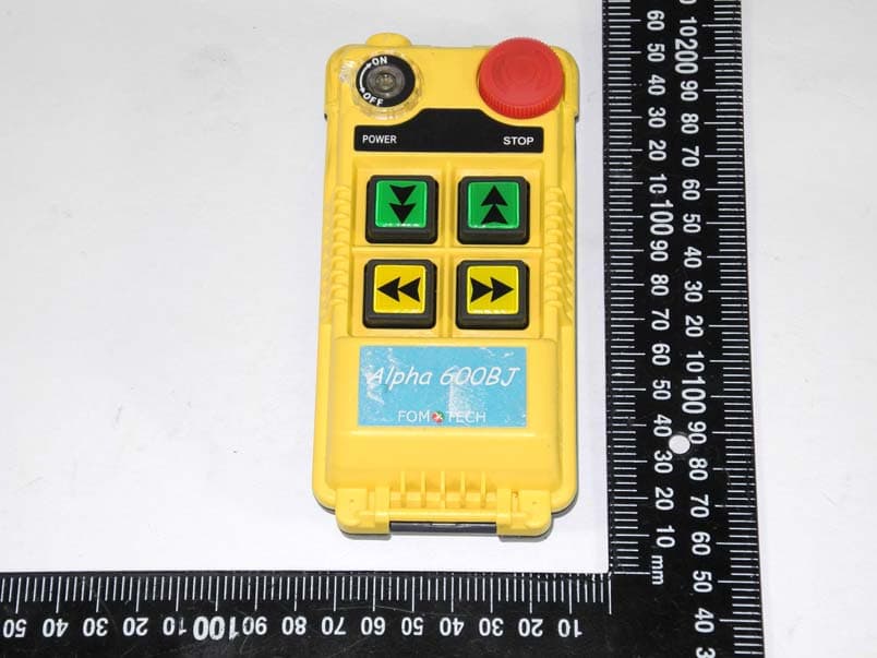
LZ6ALPHA604XJ
Jul 22, 2021Industrial Remote Control
Equipment Class
DSS - Part 15 Spread Spectrum Transmitter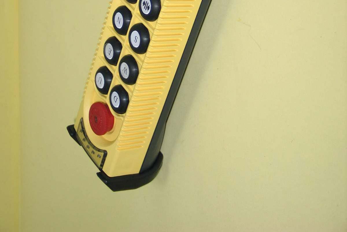
LZ6A4000SERIES
Sep 05, 2006Industrial Crane Remote Controler
Equipment Class
DSC - Part 15 Security/Remote Control Transmitter
LZ6ALPHA3000MODEL
Oct 25, 2001Industrial Radio Remote Control
Equipment Class
DSC - Part 15 Security/Remote Control Transmitter
LZ6ALPHA510SERIES
Jun 07, 2001Industrial Remote Control
Equipment Class
DSC - Part 15 Security/Remote Control Transmitter