LZX-MCD4300BT2.4 GHz Cordless Phone
Unical Enterprises Inc
Click to zoom
Application Details
- Equipment Class
- DSS - Part 15 Spread Spectrum Transmitter
- Date of Grant
- Nov 29, 2001
- Application Purpose
- Original Equipment
- Date of Application
- Nov 29, 2001
- Equipment Note
- 2.4 GHz Cordless Phone
- Frequency Range
- 2402.08000000 - 2480.00000000
- Company
- Unical Enterprises Inc
- Country
- United States
Documents & Files
Document Text
Text extracted from the exhibit documents filed with the FCC. Open a document above to read the original.
Users Manual
K-BELL CO.,LTD. BT-CT USER MANUAL 2001-11-20 1/16 EXCURSION BT-CT MANUAL NOV 20 , 2001 FCC INFORMATION ......PAGE 2 HANDSET CONTROL-CORDLESS PHONE ......PAGE 4 BASE UNIT CONTROL ......PAGE 5 OPERATION LOGIC ......PAGE 6 TELEPHONE OPERATION 1. ADD EX H/S ......PAGE 6 2. MAKE A CALL ......PAGE 6 3. ANSWER A CALL ......PAGE 6 4. REDIAL ......PAGE 6 5. PAGE OTHER H/S (2 WAY TALKING) ......PAGE 7 6. TRANSFERRING A CALL/CONFERENCE CALL ......PAGE 7 7. PAGE ALL H/S FROM BASE ......PAGE 7 8. CALL WAITING ......PAGE 7 9. OTHER ......PAGE 8 10. CID ......PAGE 8 11. FUNCTION(MENU) ......PAGE 11 12. BATTERY LOW ......PAGE 16 13. OUT OF RANGE ......PAGE 16 K-BELL CO.,LTD. BT-CT USER MANUAL 2001-11-20 2/16 FCC INFORMATION FCC Regulations This equipment has been tested and complies with the limits for a Class B digital device, pursuant to part 15 of the FCC rules. These limits are intended to provide reasonable protection against such interference in a residential installation. This equipment generates, uses, and can radiate radio frequency energy and if not installed and used in accordance with the instructions, may cause harmful interference to radio communications. However, there is no guarantee that interference will not occur in a particular installation. If this equipment does cause harmful interference to radio or television reception, which can be determined by turning the equipment off and on, the user is encouraged to try to correct the interference by one or more of the following measures : . Reorient or relocate the receiving antenna. . Increase the separation between the equipment and receiver. . Connect the equipment into an outlet on an electrical circuit different from that to which the receiver is connected. . Consult the dealer or an experienced radio/TV technician. Upon request from your telephone company, you must provide the FCC registration number and the Ringer Equivalence Number(REN) found on the bottom of your BT-CT. An FCC compliant telephone cord and modular plug are provided with this equipment. This equipment is designed to be connected to the telephone network or premises wiring using a compatible modular jack which is Part 68 compliant. FCC RF Exposure Warning: This device and its antenna(s) must not be co-located or operating in conjunction with any other antenna or transmitter. End-users must be provided with specific operating instructions for satisfying RF exposure compliance requirements. Telephone Company Procedures The goal of the telephone company is to provide you with the best service it can. In order to do this, it may occasionally have to make changes in its equipment, operations, or procedures. If these changes might affect your service or the operation of your equipment, the telephone company will give you notice in writing to allow you to make any changes necessary to maintain uninterrupted service. If you have any questions about your telephone line, such as how many pieces of equipment you can connect to it, the telephone company will provide this information upon request. In certain circumstances, it may be necessary for the telephone company to request information from you about the equipment which you have connected to your telephone line. Upon request of the telephone company, you must provide the FCC registration number and the Ringer Equivalence Number(REN) of the equipment which is connected to your line. Both of these numbers are listed on the equipment label on the bottom of your BT-CT . In most(but not all) areas, the sum of the RENs of all devices connected to one line should not exceed 5. To be certain of the number of devices you may connect to your line as determined by the REN, you should contact your local telephone company. Note: This equipment is hearing aid-compatible(HAC). Type of Service Your cordless telephone is designed for use on standard device telephone lines. The phone K-BELL CO.,LTD. BT-CT USER MANUAL 2001-11-20 3/16 connects to the telephone line with a standard jack called the USOC-RJ11C. Connection to telephone company-provided coin service (central office implemented systems) is prohibited. Connection to party line service is subject to State tariffs. If Problems Arise If any of your telephone equipment is not operating properly, you should immediately remove it from your telephone line, as it may cause harm to the telephone network. If the telephone company notes a problem, they may temporarily stop service. When practical, they will notify you before this disconnection. If advance notice is not feasible, you will be notified as soon as possible. When you are notified, you will be given the opportunity to correct the problem and will be informed of your right to file a complaint with the FCC. In the event repairs are ever needed on your cordless telephone, they should be done by an authorized representative of For information, contact Industry Canada(IC)regulations This Class B digital apparatus meets all requirements of the Canadian Interference-Causing Equipment Regulations. Cet appareil numerique de la classe B respecte toutes les exigences du Reglement sur le material brouilleur du Canada. Notice: The Canadian Department of Communications label identifies certified equipment. This certification means the equipment meets certain telecommunications network Protective, operational and safety requirements. The Department does not guarantee the equipment will operate to the customer’s satisfaction. Before installing this equipment users should ensure that it is permissible to be connected to the facilities of the local telecommunications company. The equipment must also be installed using an acceptable method of connection. Sometimes, the company’s inside wiring associated with a single line individual service may be extended with a certified connector assembly (telephone extension cord). The customer should be aware that compliance with these conditions may not prevent degradation of service in some situations. Repairs to…
Text truncated - open the document above for the full version.
External Photos
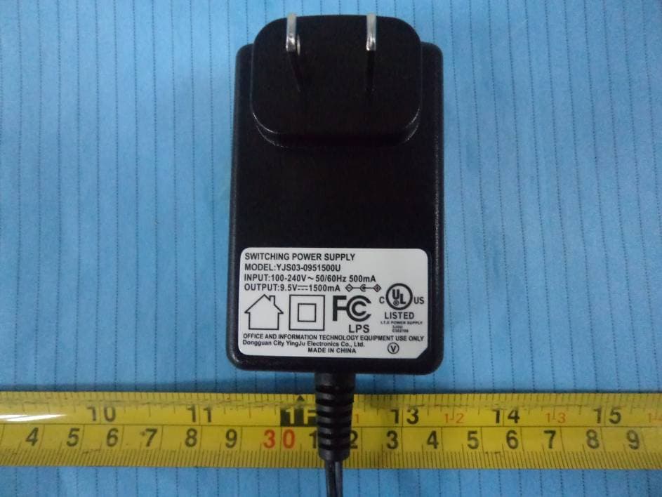
EUT PHOTOGRAPHS EUT-Top View (Base) EUT- Top View (Handset) EUT- Bottom View (Base) EUT – Bottom View (Handset) EUT- AC/DC Adapter View (Base)
ID Label/Location Info
FCC PRODUCT LABELING AND WARNING STATEMENT FCC ID Label Specifications : Text is black or white in color and is left justified. Labels are silk- screened and shall be “permanently affixed” at a conspicuous location on the EUT. Proposed Label Location on EUT FCC ID: LZX-MCD4300BT T h is d e v ic e c o m p lie s w ith P a rt 1 5 o f th e F C C R u le s . O p e ra tio n is s u b je c t to th e fo llo w in g tw o c o n d itio n s : (1 ) th is d e v ic e m a y n o t c a u se h a rm - ful interference, and (2) this device m ust accept any interference received, including interference that m ay cause undesired operation. 1.0" 2.1875 FCC ID: LZX-MCD4300BT Bottom View of EUT FCC ID Label Location
Internal Photos
EUT – Component View (Base) EUT- Component View (Handset) EUT- Solder View (Base) EUT – Solder View (Handset) EUT- Transmitter View (Base) EUT – Transmitter View (Handset) EUT – Battery View (Handset)
Operational Description
Output Power and Channel Separation in Different Operating Modes The different operating modes (data-mode, acquisition –mode) of the Bluetooth cordless phone (called Bluetooth device below) do not influence the output power and channel spacing. There is only one transmitter which is driven by identical input parameters concerning these parameters. Only a different hopping sequence will be used. For this reason the check of these RF parameters in one operating mode is sufficient. Frequency Range of a Bluetooth Device Hereby we declare that the maximum frequency range of this device is : 2402 – 2480 MHz. This is according to the Bluetooth Core Specification V 1.1 for devices which will be operated in the USA. Other frequency ranges (e.g. for Spain, France, Japan) which are allowed according to the Core Specification are not supported by this device. Co-ordination of the Hopping Sequence in Data Mode to Avoid Simultaneous Occupancy by Multiple Transmitters Bluetooth units which want to communicate with other units must be organized in a structure called piconet. This piconet consists of maximum of 8 Bluetooth units. One unit is the master the other seven are the slaves. The master co-ordinates frequency occupation in this piconet for all units. As the master hop sequence is derived from it’s BD address which is unique for every Bluetooth device, additional masters intending to establish new piconets will always use different hop sequences. Example of a hopping sequence in data mode Example of a 79 hopping sequence in data mode: 40, 21, 44, 23, 42, 53, 46, 55, 48, 33, 52, 35, 50, 65, 54, 67, 56, 37, 60, 39, 58, 69, 62, 71, 64, 25, 68, 27, 66, 57, 70, 59, 72, 29, 76, 31, 74, 61, 78, 63, 01, 41, 05, 43, 03, 73, 07, 75, 09, 45, 13, 47, 11, 77, 15, 00, 64, 49, 66, 53, 68, 02, 70, 06, 01, 51, 03, 55, 05, 04. Equally Average Use of Frequencies in Data Mode and Behaviour for Short Transmissions The generation of the hopping sequence in connection mode depends essentially on two input values : 1. LAP/UAP of the master of the connection 2. Internal master clock The LAP (lower address part) are the 24 LSB’s of the 48 bit BD_ADDRESS. The BD_ADDRESS is an unambiguous number of every Bluetooth unit. The UAP (upper address part) are the 24 MSB’s of the 48 bit BD_ADDRESS,. The internal clock of a Bluetooth unit is derived from a free running clock which is never adjusted and is never turned off. For synchronization with other units, only offset values are added to this clock. It has no relation to the time of day. Its resolution is at least half RX/TX slot length of 312.5 μs. The clock has a cycle of a bout one day (23h30). For the deriving of the hopping sequence the entire LAP (24bits), 4 LSB’s (4 bits) (Input 1) and the 27 MSB’s of the clock (Input 2) are used. With this input values different mathematical procedures (permutations, additions, XOR-operations) are performed to generate the sequence. This will be done at the beginning of every new transmission. Regarding shorts transmissions the Bluetooth system has the following behaviours: The first connection between the two devices is established, a hopping sequence was generated. For transmitting the wanted data the complete hopping sequence was not used. The connection ended. The second connection will be established. A new hopping sequence is generated. Due to the fact that the Bluetooth clock has a different value, because the period between the two transmission is longer (and it cannot be shorter) than the minimum resolution of the clock (312.5 μs). The hopping sequence will always differ from the first one. Receiver Input Bandwidth and Behaviour for Repeated Single or Multiple Packets The input bandwidth of the receiver is 1 MHz. In every connection one Bluetooth device is the master and the other one is the slave. The master determines the hopping sequence. The slave follows this sequence. Both devices shift between RX and TX time slot according to the clock of the master. Additionally the type of connection (e.g. single or multislot packet) is set up at the beginning of the connection. The master adapts its hopping frequency and its TX/RX timing according to the packet type of the connection. Also the slave of the connection will use these settings. Repeating of a packet has no influence on the hopping sequence. The hoping sequence generated by the master of the connection will be followed in any case. That means, a repeated packet will not be sent on the same frequency, it is sent on the next frequency of the hopping sequence. Channel Separation in Hybrid Mode As mentioned before, the nominal channel spacing of the Bluetooth system is 1 MHz independent of the operating mode. In other words, the channel spacing in hybrid mode (inquiry and page mode) is still 1 MHz without any change. Derivation and Examples for a Hopping Sequence in Hybrid Mode For the generation of the inquiry and page hop sequences the same procedures as described for the data mode are used, but this time with different input vectors: For the inquiry hop sequence, a predefined fixed address is always used. This results in the same 32 frequencies used by all devices doing an inquiry but every time with a different start frequency and phase in this sequence. For the page hop sequence, the device address of the paged unit is used as input vector. This results in the use of a subset of 32 frequencies which is specific for that initial state of the connection establishment between the two units. A page to different devices would result in a different subset of 32 frequencies. So it is also ensured that in hybrid mode the frequency use equally averaged. Example of a hopping sequence in inquiry mode : 48, 50, 09, 13, 52, 54, 41, 45, 56, 58, 11, 15, 60, 62, 43, 47, 00, 02, 64, 68, 04, 06, 17, 21, 08, 10, 66, 70, 12, 14, 19, 23 Example of a hopping sequence in paging mode : 08, 57, 68, 70, 51, 02, 42, 40, 04, 61, 44, 46, 63, 14, 50, 48, 16, 65, 52, 54, 67, 18, 58, 56, 20, 53, 60, 62, …
Text truncated - open the document above for the full version.
Test Report
Note: This test report is specially limited to the use of the above client company and the product model only. It may not be duplicated without prior written consent of Bay Area Compliance Laboratory Corporation. This report must not be used by the client to claim product endorsement by NVLAP or any agency of the U.S. Government. FCC PART 15 SUBPART C EMI MEASUREMENT AND TEST REPORT For Unical Enterprises, Inc. 16960 Gale Avenue, City of Industry, CA 91745 FCC ID: LZX-MCD4300BT November 30, 2001 This Report Concerns: Original Report Equipment Type: Cordless Phone Test Engineer: Jeff Lee Test Date: November 27, 2001 Reviewed By: John Y. Chan – Engineering Manager Prepared By: Bay Area Compliance Laboratory Corporation 230 Commercial Street Sunnyvale, CA 94085 Tel: (408) 732-9162 Fax: (408) 732 9164 Unical Enterprises, Inc. FCC ID: LZX-MCD4300BT Report # test report FCC Part 15.247 Test Report Pa ge 2 of 78 TABLE OF CONTENTS 1 - GENERAL INFORMATION..................................................................................................................................4 1.1 P RODUCT D ESCRIPTION FOR E QUIPMENT U NDER T EST (EUT) ..............................................................................4 1.2 O BJECTIVE .............................................................................................................................................................4 1.3 R ELATED S UBMITTAL ( S )/G RANT ( S ).......................................................................................................................4 1.4 T EST M ETHODOLOGY ............................................................................................................................................4 1.5 T EST F ACILITY .......................................................................................................................................................4 1.6 T EST E QUIPMENT L IST AND D ETAILS .....................................................................................................................5 1.7 E QUIPMENT U NDER T EST (EUT) ...........................................................................................................................5 1.8 L OCAL S UPPORT E QUIPMENT L IST AND D ETAILS ...................................................................................................6 1.9 E XTERNAL I/O C ABLING L IST AND D ETAILS .........................................................................................................6 2 - SYSTEM TEST CONFIGURATION.....................................................................................................................7 2.1 D ESCRIPTION OF T EST C ONFIGURATION ................................................................................................................7 2.2 E QUIPMENT M ODIFICATIONS .................................................................................................................................7 2.3 C ONFIGURATION OF T EST S YSTEM .........................................................................................................................7 2.4 T EST S ETUP B LOCK D IAGRAM ...............................................................................................................................8 3 - SUMMARY OF TEST RESULTS..........................................................................................................................9 4 - CONDUCTED OUTPUT POWER MEASUREMENT......................................................................................10 4.1 S TANDARD A PPLICABLE ......................................................................................................................................10 4.2 M EASUREMENT P ROCEDURE ................................................................................................................................10 4.3 M EASUREMENT R ESULT ......................................................................................................................................10 4.4 T EST E QUIPMENT .................................................................................................................................................10 5 – SPURIOUS EMISSION ........................................................................................................................................17 5.1 S TANDARD A PPLICABLE ......................................................................................................................................17 5.2 M EASUREMENT P ROCEDURE ................................................................................................................................17 5.3 M EASUREMENT D ATA ..........................................................................................................................................17 6 – 20 DB BANDWIDTH ............................................................................................................................................30 6.1 S TANDARD A PPLICABLE ......................................................................................................................................30 6.2 M EASUREMENT P ROCEDURE ................................................................................................................................30 6.3 M EASUREMENT D ATA ..........................................................................................................................................30 7-100 KHZ BANDWIDTH OF BAND EDGES MEASUREMENT........................................................................37 7.1 S TANDARD A PPLICABLE ......................................................................................................................................37 7.2 M EASUREMENT P ROCEDURE ................................................................................................................................37 7.3 T EST R ESULT…
Text truncated - open the document above for the full version.
Test Setup Photos
Conducted and Radiated Setup Photographs Conducted Emission – Front View (Base) Conducted Emission – Rear View (Base) Radiated Emission Setup – Front View (Base) Radiated Emission Setup – Rear View (Base) Radiated Emission Setup – Front View (Handset) Radiated Emission Setup – Rear View (Handset)
Contact Information
Applicant
Andy Chung
Test Firm
Bay Area Compliance LaboratoryJohn Chan
Technical Specifications
| # | Rule Parts | Frequency Range | Power Output |
|---|---|---|---|
| 2 | 15C | 2.40 GHz - 2.48 GHz | 30.00 mW |
Other Applications from Unical Enterprises Inc
LZXDM1500C
Dec 18, 2011DECT 6.0 Cordless Telephone with 3G Cell Phone
Equipment Class
PUB - Part 15 Unlicensed PCS Base Station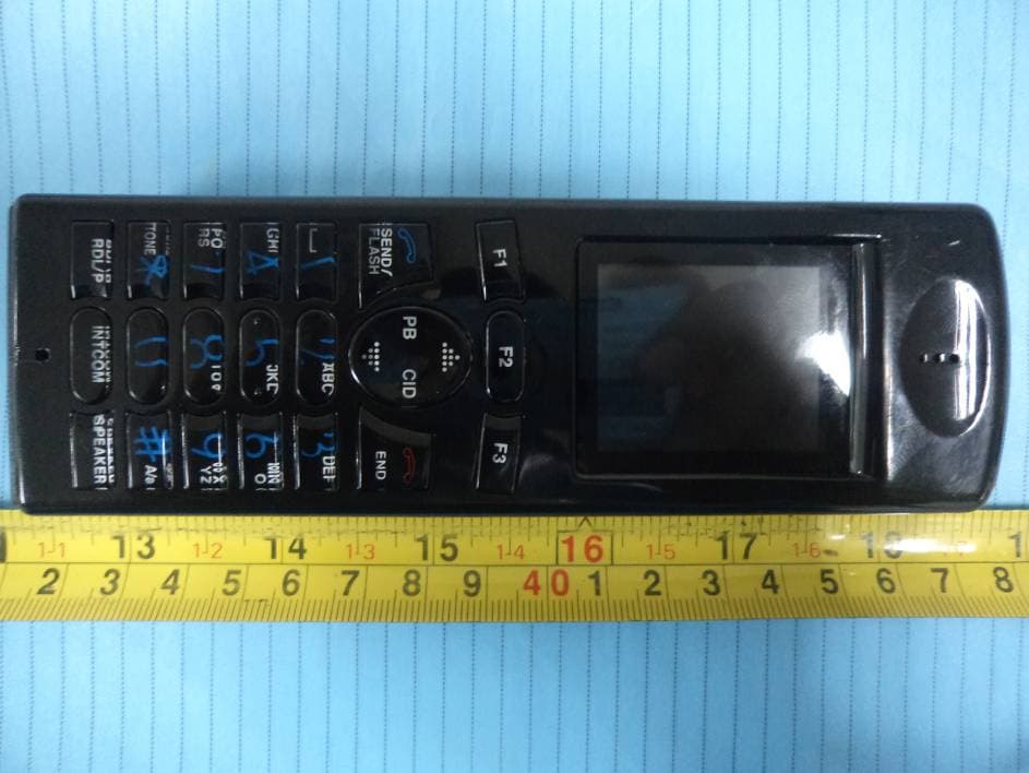
LZXDM150HS
Dec 18, 2011DECT 6.0 Cordless Telephone with 3G Cell Phone
Equipment Class
PUE - Part 15 Unlicensed PCS portable Tx held to ear
LZX-CL6065AP
Apr 20, 2011DECT 1.9 GHz Cordless Phone (USA 6.0)
Equipment Class
PUB - Part 15 Unlicensed PCS Base Station
LZX-CL6065
May 20, 2010DECT CORDLESS PHONE
Equipment Class
PUE - Part 15 Unlicensed PCS portable Tx held to ear
LZX31120-H
Feb 24, 2008UNLICENSED PCS PORTABLE TX HELD TO EAR
Equipment Class
PUE - Part 15 Unlicensed PCS portable Tx held to ear