LZX35850H2.4GHz/5.8GHz FHSS Cordless Phone w/ Caller ID
Unical Enterprises Inc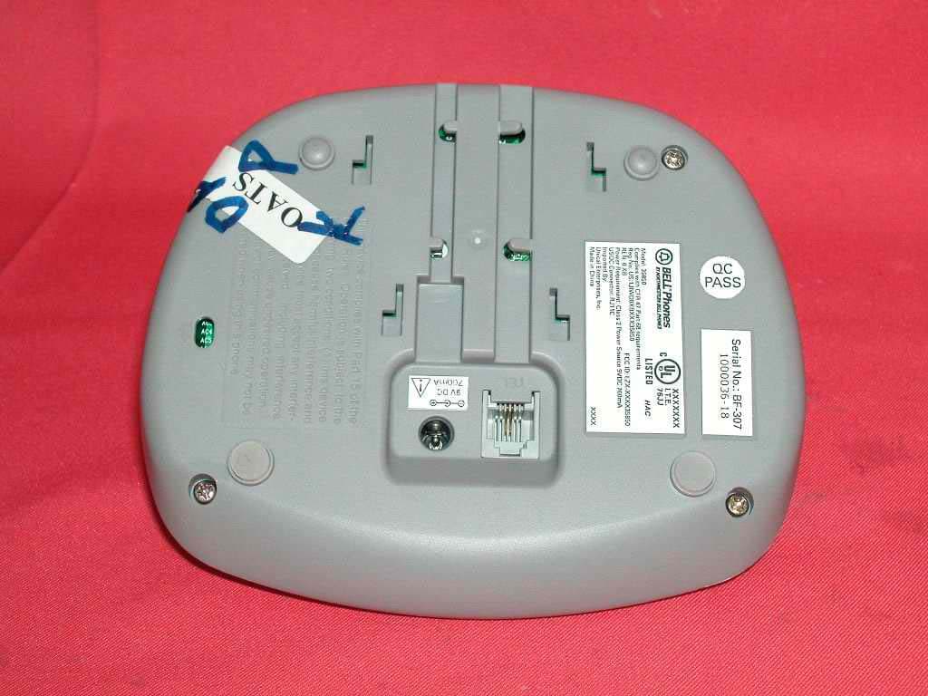
Click to zoom
Application Details
- Equipment Class
- DSS - Part 15 Spread Spectrum Transmitter
- Date of Grant
- Sep 17, 2003
- Application Purpose
- Original Equipment
- Date of Application
- Sep 17, 2003
- Equipment Note
- 2.4GHz/5.8GHz FHSS Cordless Phone w/ Caller ID
- Frequency Range
- 2401.80800000 - 2479.40100000
- Company
- Unical Enterprises Inc
- Country
- United States
Documents & Files
Document Text
Text extracted from the exhibit documents filed with the FCC. Open a document above to read the original.
Users Manual
Excursion ® 35850 Congratulations on your selection of the Model: 35850 model from Northwestern Bell Phones. This quality 5.8GHz digital cordless telephone with Caller ID on Call Waiting, like all Genuine BELL® products, has been designed to give you many years of continuous service and represents the best value for your money. This phone is built on the state-of-the- art Frequency Hopping Digital Spread Spectrum radio communication technology for high quality voice communication and high level of conversation privacy. It requires little maintenance and is easy to setup and operate. 1 05111A-1 IMPORTANT SERVICE INFORMATION Read this manual before attempting to setup or use this instrument. It contains important information regarding safe installation and use. Keep this manual for future reference. Also save the carton, packing and proof of purchase to simplify and accelerate any needed action. If you need assistance or service, call (800) 888-8990 between 8:00 a.m. and 4:30 p.m. Pacific Standard Time, Monday through Friday. You can also visit our web site at: http://www.nwbphones.com for technical support and information on our other products. WARNING To prevent fire or shock hazard, do not expose this product to rain or any type of excess moisture. If accidentally dropped into water, the adapter should immediately be unplugged from the wall along with the telephone line cord. CAUTION To maintain compliance with the FCC’s RF exposure, place the base unit at least 20cm from nearby persons. THIS SYMBOL IS INTENDED TO ALERT THE USER OF THE PRESENCE OF IMPORTANT OPERATING AND MAINTENANCE (SERVICING) INSTRUCTIONS IN THE OWNER'S MANUAL. 2 CARTON CONTENTS HANDSET x2 BASE UNIT EXTRA BASE RECHARGEABLE WALL MOUNT BELT CLIP x2 Ni-Mh BATTERY PACK x2 BRACKET ADAPTER ADAPTER TELEPHONE (DC9V, 700mA) (DC9V, 300mA) LINE CORD (already attached cradle) USER’S MANUAL WARRANTY CARD ACCESSORY ORDER FORM G X 2411ci %(// 3OL 3 05111A-1 SAVE THESE INSTRUCTIONS IMPORTANT SAFETY INSTRUCTIONS When using your telephone equipment, basic safety precautions should always be followed to reduce the risk of fire, electric shock, and injury to persons, including the following: 1. Read and understand all instructions. 2. Keep base unit at least 20cm distance apart from a person. 3. Follow all warnings and instructions marked on the product. 4. Unplug this product from the wall outlet before cleaning. Do not use liquid cleaners or aerosol cleaners. Use a damp cloth for cleaning. 5. Do not use this product near water, for example, near a bathtub, washbowl, kitchen sink, laundry tub, in a wet basement or near a swimming pool. 6. Do not place this product on an unstable cart, stand, or table. The product may fall, causing serious damage to the product. 7. Slots and openings in the cabinet at the back or bottom are provided for ventilation, to protect it from overheating. These openings should never be blocked or covered. The openings should never be blocked by placing the product on the bed, sofa, rug, or other similar surface. This product should never be placed near or over a radiator or heat register. This product should not be placed in a built-in installation unless proper ventilation is provided. 8. This product should be operated only from the type of power source indicated on the marking label. If you are not sure of the type of power supply to your home, consult your dealer or local power company. 9. Do not allow anything to rest on the power cord. Do not locate this product where the cord will be abused by persons walking on it. 10. Do not overload wall outlets and extension cords as this can result in the risk of fire or electric shock. 11. Never push objects of any kind into this product through cabinet slots as they may touch dangerous voltage points or short out parts that could result in a risk of fire or electric shock. Never spill liquid of any kind on the product. 12. To reduce the risk of electric shock, do not disassemble this product, but take it to a qualified service contractor when some service or repair work is required. Opening or removing covers may expose you to dangerous voltages or other risks. Incorrect reassembly can cause electric shock when the appliance is subsequently used. 13. Unplug this product from the wall outlet and refer servicing to qualified service personnel under the following conditions: A. When the power supply cord or plug is damaged or frayed. B. If liquid has been spilled into the product. C. If the product has been exposed to rain or water. D. If the product does not operate normally by following the operating instructions. Adjust only those controls that are covered by the operating instructions. Improper adjustments of other controls may result in damage and will often require extensive work by a qualified technician to restore the product to normal operation. E. If the product has been dropped or the cabinet has been damaged. F. If the product exhibits a distinctive change in performance. 13. Avoid using a telephone (other than a cordless type) during an electrical storm. There maybe a remote risk of electric shock from lightning. 14. Do not use the telephone to report a gas leak in the vicinity of the leak. 4 SAVE THESE INSTRUCTIONS BATTERY SAFETY INSTRUCTIONS CAUTION: To reduce the risk of fire or injury to persons, read and follow these instructions: 1. Use only the following type and size of handset battery pack: Cordless Telephone Battery Pack DC3.6V, 850mAh, Ni-MH Battery Pack 2. Do not dispose of the battery in a fire. The cell may explode. Check with local codes for possible special disposal instructions. 3. Do not open or mutilate the battery. Released electrolyte is corrosive and may cause damage to the eyes or skin. It may be toxic if swallowed. 4. Exercise care in handling the battery in order not to short the battery with conducting material such as rings, bracelets and keys. The battery or conductor may overheat and cause burns. 5. Recharge only the batter…
Text truncated - open the document above for the full version.
Users Manual
5 05111A-1 FCC NOTICE The FCC requires that you be advised of certain requirements involving the use of this telephone. 1. This telephone is Hearing Aid Compatible. 2. On the bottom of this equipment is a label that contains, among other information, a product identifier in the form US:AAAEQ##TXXXX. You must, upon request, provide this information to your telephone company. The digits represented by ## in the product identifier indicate the Ringer Equivalency Number (REN) for this equipment. The REN is useful in determining the number of devices you may connect to your telephone line and still have all of these devices ring when your telephone number is called. In most (but not all) areas, the sum of the RENs of all devices connected to one line should not exceed 5. To be certain of the number of devices you may connect to your line as determined by the REN, contact your local telephone company. 3. This equipment complies with 47C FR Part 68 of the FCC rules. On the bottom of this equipment is a label that contains, among other information, the FCC registration number and Ringer Equivalence Number (REN) for this equipment. If requested, provide this information to your telephone company. 4. The REN is useful to determine the quantity of devices you may connect to your telephone line and still have all of those devices ring when your number is called. In most, but not all areas, the sum of the RENs of all devices should not exceed five (5.0). To be certain of the number of devices that you may connect to your line, as determined by the REN, you should call your local telephone company to determine the maximum REN for your calling area. 5. To maintain compliance with the FCC’s RF exposure guidelines, place the base unit at least 20cm from nearby persons. 6. If your telephone causes harm to the telephone network, the telephone company may discontinue your service temporarily. If possible, they will notify you in advance. But if advance notice is not practical, you will be notified as soon as possible. You will be advised of your right to file a complaint with the FCC. 7. Your telephone company may make changes to its facilities, equipment, operations or procedures that could affect the proper operation of your equipment. If they do, you will be given advance notice so as to give you an opportunity to maintain uninterrupted service. 8. If you experience trouble with the telephone, please contact VTC Service & Manufacturing Co., Inc. at (800) 888-8990 or write to: VTC Customer Service, 16988 Gale Ave., City of Industry, CA 91745 for repair/warranty information. The telephone company may ask you to disconnect this equipment from the network until the problem has been corrected or you are sure that the equipment is not malfunctioning. 9. This equipment may not be used on coin service provided by the telephone company. Connection to party line service is subject to state tariffs.(Contact your state public utility commission or corporation commission for information). 10. WARNING: Changes or modifications to this unit not expressly approved by the party responsible for compliance could void the user’s authority to operate the equipment. NOTE: This equipment has been tested and found, complies with the limits for a class B digital device, pursuant to Part 15 of the FCC Rules. These limits are designed to provide reasonable protection against harmful interference in residential installation. This equipment generates, uses and can radiate radio frequency energy. If not installed and used in accordance with the instruction, may cause harmful interference to radio communications. However, there is no guarantee that interference will not occur in a particular installation. If this equipment does cause harmful interference to radio or television reception, which can be determined by turning the equipment off and on, the user is encouraged to try to correct the interference by one or more of the following measure: • Increase the separation between the equipment and receiver. • Connect the equipment into an outlet on a circuit different from that to which the receiver needed. • Consult the dealer of an experienced radio / TV technician for help. 12. USOC jack type is RJ11C and the compatible jack is Part 68 compliance. 13. If your home has specially wired alarm equipment connected to the telephone line, ensure the installation of this cordless phone does not disable your alarm equipment. If you have questions
Block Diagram
PDF created with FinePrint pdfFactory trial version www.pdffactory.com
External Photos
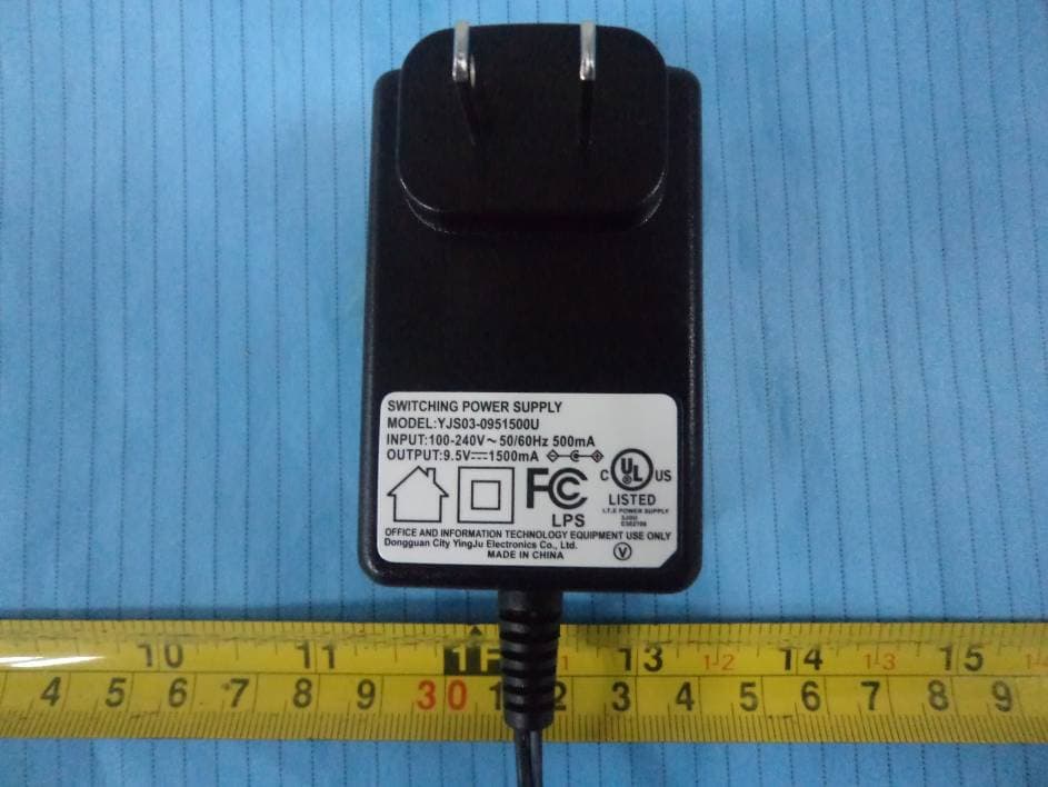
External photos FCC ID: LZX35850H External photos FCC ID: LZX35850H
Internal Photos
Internal photos FCC ID: LZX35850H Handset assembly Handset Main PCB comp side Internal photos FCC ID: LZX35850H Handset Main PCB display side (View 1) Handset Main PCB display side (View 2) Internal photos FCC ID: LZX35850H Handset Oscillator PCB comp side (View 1) Handset Oscillator PCB comp side (View 2) Internal photos FCC ID: LZX35850H Handset Oscillator PCB comp side (View 3)
Operational Description
Circuit Description Model: 35850 --------------------------------------------------------------------------------------------------------------------------------------- The following circuit description for model 35850 is based on the circuit diagram and block diagram of 35850 Handset Unit 1. Receiving Path The receiving path is established as below sections Antenna, Low Noise Filter, Mixer, Band Pass Filters, and Demodulator RF signal is pick up by a RX soft wire antenna (ANT1) and then filtered by the 5.8GHz Band Pass filter (F1), it then go through the 5.8GHz Low Noise Filter make by 2SC5594 (Q5), and then mix with the 3.36GHz signal which produced by S1T8825B (U2) PLL IC, 2SC5066 (Q3), BFR183T (Q4) and 2SC5594 (Q6) Local Oscillator, and the 3.36GHz Band Pass Filter constructed by L15 and C75 in the NESG2031 (Q7) Mixer. After that, the signal passes the 2.4GHz Band Pass Filter make by L1 and C13. Finally it inputs to RX of U1 (DH24RF17) transceiver IC. Then though mixer and FSK data output from demodulator FSK data demodulate The FSK data is output form DH24RF17 transceiver IC, then go to EDCT controller chip DLH36107 for decode to an audio signal before output to the handset speaker though audio amplifier. 2. Transmitting Path The transmitting path is established as below sections Mic amplifier and encoder Audio signal pick up by handset microphone is amplified by internal mic amplifier of U2 DLH36107 EDCT controller, then go to encoding. Modulator, RF Power amplifier and Antenna The FSK data is output from the EDCT controller chip, then input to transceiver IC DH24RF17. The modulated signals go to power amplifier is constructed by Q1A (2SC5754), then pass though the 2.4GHz Band Pass Filter (FL1). Finally, the RF signal propagates though a TX solid wire antenna (ANT2). Base Unit 1. Receiving Path The receiving path is established as below sections Antenna, Mixer, Demodulator RF signal is picked up by a RX solid wire antenna (ANT2) and then filtered by the 2.4GHz Band Pass filter (FL2), and input to RX of U1 (DH24RF17) transceiver IC. Then though mixer and FSK data output from demodulator FSK data demodulate The FSK data is output form DH24RF17 transceiver IC, then go to EDCT controller chip DLH36119 for decode to an audio signal before output to the handset speaker though audio amplifier. 2. Transmitting Path The transmitting path is established as below sections Amplifier and encoder Audio signal come from line interface is amplified by internal amplifier of U2 DLH36119 EDCT controller, then go to encoding. Antenna, Low Noise Filter, Mixer, Band Pass Filters, and Modulator The FSK data is output from the EDCT controller chip, then input to transceiver IC DH24RF17. The 2.4GHz modulated signals first mix with the 3.36GHz signal produced by S1T8825B (U2) PLL IC, 2SC5065 (Q8, Q3), 2C5594 (Q5) Local Oscillator, 3.36GHz Band Pass Filter (F3) in NESG2031 (Q4) Mixer to produce a 5.8GHz signal. The 5.8GHz signal then pass through the 5.8GHz Band Pass Filter (F1) before it pass the Buffer Amplifier constructed by Q6, Q7 2SC5594, and Q10 NESG2031. After that, it goes through a 5.8GHz Band Pass Filter (F4) and input to Murata XM5060PC Power Amplifier IC. Finally, after it passing a Low Pass Filter constructed by C23 and C90, the RF signal propagate through a TX solid wire antenna (ANT1) 3. Telephone Line interface The telephone line interface circuit is established by below sections Line seize and isolation Line isolation is mainly preformed by Q13, Q14 and Q8. Q8 also has a function of controlling Line-seize. Both audio input and output will though Q13 and Q14. Ring detect circuit and Caller ID System. Q5 is used for AC power amplifier for ring signal, which is input though R46, R48 470K ohm and C53, C60 100nF/100V as DC isolation from telephone line. The CID signals though C43, C44, R113 and R114 input to U1 DLH36119 EDCT controller to demodulate the CID data then displayed on the Handset LCD display. Technical Documents For 5.8GHz/ 2.4GHz Hybrid EDCT FHSS System Models 35850/ 35858 PDF created with FinePrint pdfFactory trial version www.pdffactory.com Page 2 of 2 Table of Contents DEFINITIONS, ACRONYMS AND ABBREVIATIONS............................................................4 1 INTRODUCTION.......................................................................................................................5 1.1 SCOPE.........................................................................................................................................5 2 BRIEF SYSTEM DESCRIPTION...........................................................................................6 2.1 FREQUENCY CHANNELS............................................................................................................6 2.2 TDMA FRAMES STRUCTURE....................................................................................................7 2.3 RESIDENTIAL / DOMESTIC SYSTEM..........................................................................................7 2.4 BEARERS....................................................................................................................................8 3 OVERVIEW OF FREQUENCY HOPPING ALGORITHM............................................10 3.1 HOPPING RATE.........................................................................................................................10 3.2 HOPPING SEQUENCE................................................................................................................10 3.2.1 HOPPING PATTERN BASE-TABLE............................................................................................10 3.2.2 LCG RANDOM NUMBER GENERATOR....................................................................................11 3.2.3 LOGICAL AND PHYSICAL CHANNEL NUMBERS......................................................................11 3.3 IDENTIFYING CHANNEL INTERFERENCE.....................................................…
Text truncated - open the document above for the full version.
Operational Description
Security code description: For handset: PSN has 20 bits, it has 1048576 combination. In production, each handset will assign a PSN in sequence. For base: FPN has 17 bits, it has 131072 combination. In production, each base will assign a FPN in sequence. In production, the handset will do the registration with the base. After that, handset can link up with base. After registraion , the handset will store the base FPN in eeprom, and base will store the handset PSN in eeprom. For extra handset: In production, each handset will assign a PSN in sequence. If user buy extra handset .The handset need to do registration with the base manually before using. After registraion , the handset will store the base FPN in eeprom, and base will store the handset PSN in eeprom. Registraion procdure: 1. hold base "prog" key until LED flash. 2. choose "registration" in handset manual. 3. press "menu" key to confirm. 4. Handset LCD will show "confirm message" if registration is successful.
RF Exposure Info
Intertek Testing Services FCC ID: LZX35850H Date: Aug 23, 2003 For SAR evaluation of the handset, refer to TCB Exclusions List Revised on 17 July 2002. Potable transmitter with output power less than 60/fGHz (d < 2.5cm) can be certified by TCB without the SAR evaluation. In fact, the Output power for portable transmitters is the higher of the conducted or radiated (EIRP) source-based time-averaged output. And the fGHz is mid- band frequency in GHz, and d is the distance to a person’s body, excluding hands, wrists, feet, and ankles. For the tested model of 35850, the measured peak conducted power was 79.4mW and the source-based time averaged output power was 7.7mW as TX duty cycle of the handset is 9.714%. The maximum field strength (FS) was 110.1dBμV/m at 2401.808MHz. The distance (D) between the antenna and the equipment under test (EUT) was 3 meters. From these data, the EIRP can be calculated by: EIRP = (FS*D) 2 / 30 = 77.1mW Source-based time averaged output power = (77.1*0.09714) mW = 7.49mW Based on the above calculation, it is concluded that the handset can be certified by TCB without the SAR evaluation.
Schematics
X00HR00.sch-1 - Mon Apr 14 11:11:42 2003 X00HR00.sch-2 - Mon Apr 14 11:12:00 2003
Test Report
E FCC ID: LZX35850H Intertek Testing Services Hong Kong Ltd. 2/F., Garment Centre, 576 Castle Peak Road, Kowloon, Hong Kong. Tel: (852) 2173 8888 Fax: (852) 2741 1693 Website: www.hk.intertek-etlsemko.com September 11, 2003 Tech-Vision Communications Ltd. Flat C-D, 12/F., Universal Industrial Centre, 19-25 Shan Mei Street, Fotan, N.T., Hong Kong. Tel. : (852) 2649 2102 Fax. : (852) 2647 0157 Dear Mr. Keith Chan: Enclosed you will find your file copy of a Part 15 Certification (FCC ID: LZX35850H). For your reference, TCB will normally take another 15-20 days for reviewing the report. Approval will then be granted when no query is sorted. Please contact me if you have any questions regarding the enclosed material. Sincerely, Tommy Leung Supervisor Enclosure E • The test results reported in this report shall refer only to the sample actually tested and shall not refer or be deemed to refer to bulk from which such a sample may be said to have been obtained. • This report shall not be reproduced except in full without prior authorization form Giant Electronics Limited Limited FCC ID: LZX35850H Intertek Testing Services Hong Kong Ltd. 2/F., Garment Centre, 576 Castle Peak Road, Kowloon, Hong Kong. Tel: (852) 2173 8888 Fax: (852) 2741 1693 Website: www.hk.intertek-etlsemko.com Unical Enterprises Inc. Application For Certification 2.4GHz/ 5.8GHz Frequency Hopping Spread Spectrum Cordless Phone with Caller ID - Handset (FCC ID: LZX35850H) WO# 03109982 TL/Ann Choy September 11, 2003 INTERTEK TESTING SERVICES FCC ID: LZX35850H i LIST OF EXHIBITS INTRODUCTION EXHIBIT 1: Summary of Tests EXHIBIT 2: General Description EXHIBIT 3: System Test Configuration EXHIBIT 4: Measurement Results EXHIBIT 5: Equipment Photographs EXHIBIT 6: Product Labelling EXHIBIT 7: Technical Specifications EXHIBIT 8: Instruction Manual EXHIBIT 9: Security Code Information INTERTEK TESTING SERVICES FCC ID: LZX35850H ii MEASUREMENT/TECHNICAL REPORT Unical Enterprises Inc.- MODEL: 35850-XX FCC ID: LZX35850H This report concerns (check one) Original Grant X Class II Change Equipment Type: DSS-Part 15 Spread Spectrum Transmitter Deferred grant requested per 47 CFR 0.457(d)(1)(ii)? Yes No X If yes, defer until : date Company Name agrees to notify the Commission by: date of the intended date of announcement of the product so that the grant can be issued on that date. Transition Rules Request per 15.37? Yes No X If no, assumed Part 15, Subpart C for intentional radiator - the new 47 CFR [08- 20-02 Edition] provision. Report prepared by: Tommy Leung Intertek Testing Services 2/F., Garment Centre, 576 Castle Peak Road, Kowloon, Hong Kong. Phone: 852-2173-8538 Fax: 852-2741-1693 INTERTEK TESTING SERVICES FCC ID: LZX35850H iii Table of Contents 1.0 Summary of test results..............................................................................2 2.0 General Description..............................................................................................................4 2.1 Product Description.............................................................................................................4 2.2 Related Submittal(s) Grants...............................................................................................5 2.3 Test Methodology................................................................................................................5 2.4 Test Facility...........................................................................................................................5 3.0 System Test Configuration.................................................................................................7 3.1 Justification...........................................................................................................................7 3.2 EUT Exercising Software....................................................................................................7 3.3 Support Equipment List and Description...........................................................................8 3.4 Measurement Uncertainty..................................................................................................9 3.5 Equipment Modification.......................................................................................................9 4.0 Measurement Results........................................................................................................11 4.1 Maximum Conducted Output Power at Antenna Terminals..........................................11 4.2 Maximum 20 dB RF Bandwidth........................................................................................12 4.3 Minimum Number of Hopping Frequencies....................................................................13 4.4 Minimum Hopping Channel Carrier Frequency Separation..........................................14 4.5 Average Time of Occupancy............................................................................................15 4.6 Out of Band Conducted Emissions..................................................................................16 4.7 Out of Band Radiated Emissions.....................................................................................17 4.8 Transmitter Radiated Emissions in Restricted Bands....................................................18 4.9 Field Strength Calculation.................................................................................................19 4.10 Radiated Emission Configuration Photograph - Handset............................................20 4.11 Radiated Emission Data - Handset................................................................................21 4.12 Radiated Emission from Digital Section of Transceiver...............................................25 4.13 Transmitter Duty Cycle Calculation and Measurements...........................................27 5.0 Equipment Photographs........................................................................…
Text truncated - open the document above for the full version.
Test Setup Photos
The Worst Case Configuration Photographs FCC ID: LZX35850H Radiated Emission – Handset Front View Rear View
Contact Information
Applicant
Andy Chung
Technical Contact
Intertek Testing Services Hong Kong Ltd.Tommy Leung
[email protected]852-2173-8538
2/F., Garment Centre, · Kowloon, · Hong Kong
Non-Technical Contact
Intertek Testing Services Hong Kong Ltd.Tommy Leung
[email protected]852-2173-8538
Test Firm
Intertek Testing Services Hong KongBilly Chow
Technical Specifications
| # | Rule Parts | Frequency Range | Power Output |
|---|---|---|---|
| 1 | 15C | 2.40 GHz - 2.48 GHz | 79.00 mW |
Other Applications from Unical Enterprises Inc
LZXDM1500C
Dec 18, 2011DECT 6.0 Cordless Telephone with 3G Cell Phone
Equipment Class
PUB - Part 15 Unlicensed PCS Base Station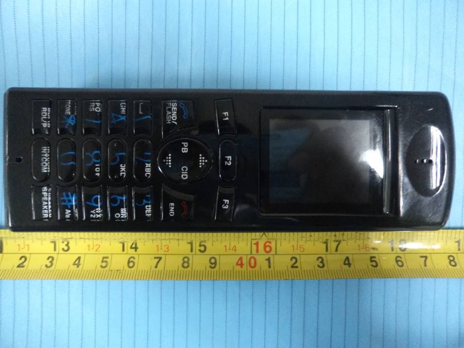
LZXDM150HS
Dec 18, 2011DECT 6.0 Cordless Telephone with 3G Cell Phone
Equipment Class
PUE - Part 15 Unlicensed PCS portable Tx held to ear
LZX-CL6065AP
Apr 20, 2011DECT 1.9 GHz Cordless Phone (USA 6.0)
Equipment Class
PUB - Part 15 Unlicensed PCS Base Station
LZX-CL6065
May 20, 2010DECT CORDLESS PHONE
Equipment Class
PUE - Part 15 Unlicensed PCS portable Tx held to ear
LZX31120-H
Feb 24, 2008UNLICENSED PCS PORTABLE TX HELD TO EAR
Equipment Class
PUE - Part 15 Unlicensed PCS portable Tx held to ear