M2EKF600Automatic door activator
Agilis Communication Technologies Pte Ltd
Click to zoom
Application Details
- Equipment Class
- FDS - Part 15 Field Disturbance Sensor
- Date of Grant
- Nov 10, 2002
- Application Purpose
- Original Equipment
- Date of Application
- Nov 10, 2002
- Equipment Note
- Automatic door activator
- Frequency Range
- 10500.00000000 - 10550.00000000
- Country
- Singapore
Documents & Files
Document Text
Text extracted from the exhibit documents filed with the FCC. Open a document above to read the original.
Users Manual
M ODELS A VAILABLE Depending on the frequency & antenna pattern required, the KF Series have just the right model for your requirements. FrequencyAntenna PatternModel 10.525GHz Narrow Wide KF600 KF610 O VERVIEW I NSTALLATION Step 1:Remove the casing cover by gently pushing a screwdriver into the slot (a) and jack-out the top casing. Step 2: Using the “Drilling Template” as a guide, use drill or pouch out holes for screw (b) and cable-entry (c). Step 3: Mounting KF600 - Run the wire through the cable-entry - Screw and mount the detector onto the wall or surface. Step 4: Connect the cable to the terminal block (d). Step 5: Next, turn on the power supply. On power up, the LED will blink 5 times. In normal operation, LED will only turn ON when a motion is detected. Note: If the sensor triggers unnecessarily, adjust the sensitivity level to obtain the most optimal working performance. A NTENNA A DJUSTMENT Tilting the antenna is easy. First, loose the (e) antenna thumbscrew on the side of the holder as indicated below. Next, tilt antenna to desired angle. Hold by the sides to rotate the antenna. Later, tighten the thumbscrew to lock the position. (a) Jack out the casing using a screwdriver Antenna thumb-screw Hold by the sides to rotate antenna Hold the metal clips to tilt antenna (c) Cables-entry (b) Mounting screws (d) Terminal Block P1 IM02960072 Rev C Drill 2x3mm holes here. W ARNING Changes or modifications made to this KF sensor not expressly approved by the manufacturer may void the FCC authorisation to operate this sensor. Mounting Hole Drilling Template S ETTINGS 4 settings can be modified through the PCB. They are: - ∑ Sensitivity ∑ Time-Delay ∑ Uni/Bi-Directional Detection ∑ Default setting Note: For ‘Sensitivity’ or ‘Time-Delay’ settings, the current value is indicated by the number of blinks displayed by the LED. i) Sensitivity Step 1 : Short P1 (Left-hand side of the PCB). Step 2 :To decrease ‘Sensitivity’, press ‘S1’, to increase, press ‘S2’. ii) Time-Delay Step 1 : Open P1. Step 2 : To decrease ‘Time-Delay’, press ‘S1’, to increase, press ‘S2’. SettingTime delay (sec) 10.5 21 31.5 42 53 64 75 87 99 iii) Uni/Bi-Directional Step 1 : Open P1. Step 2 :Press & hold both ‘S1’ & ’S2’ for about 2 sec. [LED will blink twice to indicate Uni-directional, blink once to indicate Bi-directional.] iv) Reset to Factory Setting Step 1 : Short P1. Step 2 : Press & hold both ‘S1’ & ’S2’ for about 2 sec. [LED will blink 1 long, 1 short, 1 long & 1 short.] Factory Settings; - Sensitivity : Level 4 Time-Delay: Level 1 (~0.5sec) D IRECTIONAL I NDICATION The KF Series door sensor comes with the selection of either Uni or Bi directional detection. For Bi- directional, when target is approaching the sensor, the LED will turn ON continuously. On receding, the LED is OFF and ignored the motion. For Uni- directional, when target motion is detected within the detecting zone, LED will turn ON. W IRES C ONNECTION C OVERAGE P ATTERN / O RDER I NFO PatternRangeModels Narrow Wide 3.2 x 2 m 2 2 x 6 m 2 KF600 KF610 Sensing field below correspond to the following adjustments: Å Mounting height : 3m ; Ç Vertical angle of the antenna: 40 ∞ . T ECHINCIAL D ETAILS Power Supply9~24 V AC /V DC Mains Frequency50~60Hz Frequency (X-band)10.525 GHz DirectionBi-directional / Uni-directional Function IndicationLED Relay Output0.5 A , Form ‘C’, 30 V DC / 120 V AC Time Delay0.5 ~ 9 sec Power Consumption Standby200mW @ 9V Operation550mW @ 9V Detection Angle Adjustable,0~90 ∞ Vertical, ± 30 ∞ Lateral Operating Temp. -20 ∞ C ~ +55 ∞ C Relative Humidity0 ~ 95 % Mounting StyleWall Max. Mounting Height3m Dimension (LxBxH)123 x 56 x 64 mm 2 Weight (g) 115g Accessories 2 m length cable (5 core) ; 1 set x Mounting Screws Note: 1. Install the activator on a rigid smooth surfaces not affected by vibrations at the height of 2~3m. 2. All specifications is subjected to change without prior notice. This device complies with Part 15 of the FCC Rules Operation is subject to the following two conditions: (1) This device my not cause harmful interference, and (2) This device must accept any interference received, including interference that may cause undesired operation. Narrow 2101 23 1 2 3 0 4 3 5 Wide Red White Connect to Power Supply Blue Green N/O Grey N/C COM Relay
Cover Letter(s)
CONFIDENTIALITY REQUEST Federal Communication Commission Equipment Authorization Division, Application Processing Branch 7435 Oakland Mills Road Columbia, MD 21048 November 06, 2002 TO WHOM IT MAY CONCERN Pursuant to Paragraphs §0.457 and 0.459 of the Commission’s Rules (47 C.F.R.) and Section §552(b)(4) of the Freedom of Information Act, Agilis Communication Technologies Private Limited requests confidentiality for the following products: FCC ID Number Product Title/Model M2EKF600KF600 Automatic Door Activator M2EKF610KF610 Automatic Door Activator M2EKF620KF620 Automatic Door Activator For the product stated above, we request that the following information be held confidential: 1.Circuit diagrams and BOMs submitted as Equipment Authorization Electronic Filing attachment: "schematics”. 2. Block diagram submitted as Equipment Authorization Electronic Filing attachment: “blockdiagram”. 3. Operational description submitted as Equipment Authorization Electronic Filing attachment: “operational description” The above exhibits contain Agilis’s trade secrets and proprietary information that could be of benefit to our competitors regarding the design of our mobile handset. This material is not customarily available to the general public and we request that it be withheld from public inspection. If you have any questions, please feel free to contact me at the address shown below. Sincerely, Patrick Lim Agilis Communication Technologies Pte Ltd 100 Jurong East St 21 Level 4, Singapore Technology Building Singapore 609602 Tel: +65 6568 7472 Fax: +65 6567 6370 Email: [email protected]
External Photos
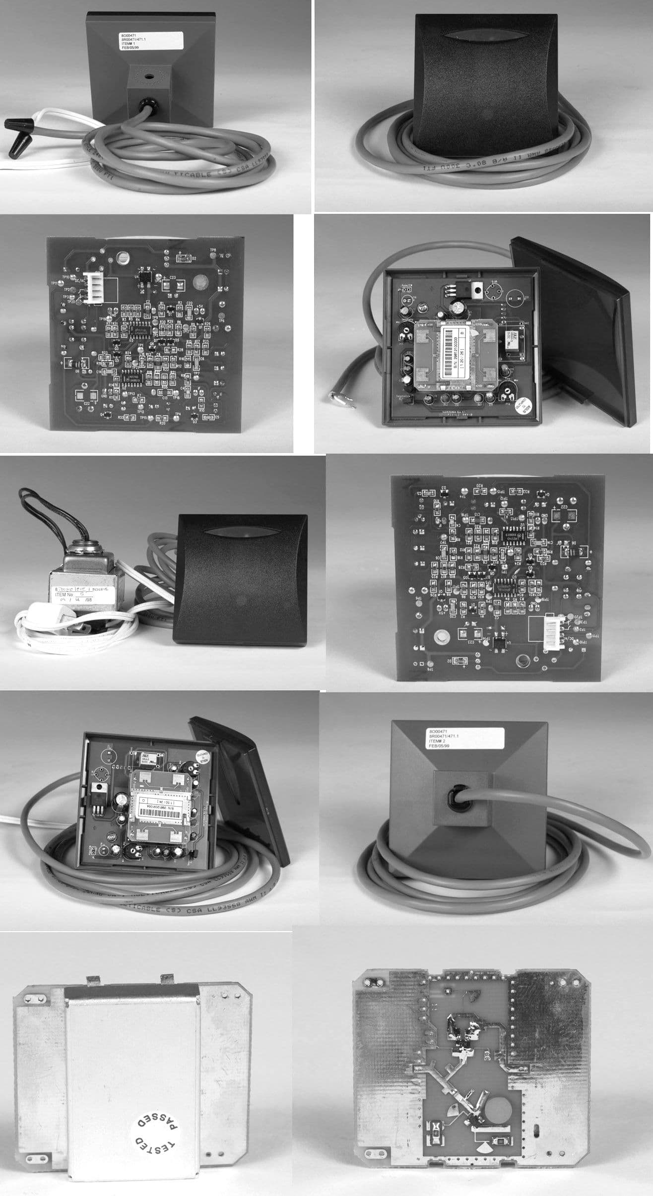
CETECOMICTServicesGmbH TestreportNo.:2-2869-01-02/02Date:19.09.2002Page59of64 4.Photographs Topview CETECOMICTServicesGmbH TestreportNo.:2-2869-01-02/02Date:19.09.2002Page60of64 Sideview
Internal Photos
CETECOMICTServicesGmbH Test report No.: 2-2869-01-02/02 Date : 19.09.2002 Page 61 of 64 Top view PCB with antenna module CETECOMICTServicesGmbH Test report No.: 2-2869-01-02/02 Date : 19.09.2002 Page 62 of 64 Bottomview PCB CETECOMICTServicesGmbH Test report No.: 2-2869-01-02/02 Date : 19.09.2002 Page 63 of 64 Antenna modules 10.525 GHz CETECOMICTServicesGmbH Test report No.: 2-2869-01-02/02 Date : 19.09.2002 Page 64 of 64 Antenna modules 10.525 GHz
Test Report
CETECOM ICT Services GmbH Radio Satellite Communication Untertürkheimer Straße 6–10, D-66117 Saarbrücken, Telephone +49 (0) 681 598 - 0 , Fax +49 (0) 681 598 – 9 075 Test report No.: 2-2869-01-02/02This test report consists of 67 pagesPage 1 of 67 Recognized by the Federal Communications Commission FCC–Identification Number TCB ID: DE001 Accredited by the German Accreditation Council DAR–Registration Number TTI–P–G 166/98-30 Independent ETSI compliance test house ETSI Test report No.: 2-2869-01-02/02 Applicant: Agilis Communication Type: KF 600, KF 610, KF 620 CETECOM ICT Services GmbH Test report No.: 2-2869-01-02/02Date : 08.11.2002Page 2 of 67 Table of contentsPage 1.General information............................................................................ 3 1.1Notes.................................................................................................... 3 1.2Testing laboratory................................................................................. 4 1.3Details of applicant................................................................................4 1.4Application details................................................................................. 4 1.5Test item (EUT).....................................................................................5 1.6Technical data.......................................................................................5 1.6.1Operation conditions............................................................................. 5 1.6.2Equipment under test............................................................................ 5 1.7Test standards...................................................................................... 6 2.Technical tests.................................................................................... 7 2.1Summary of test results........................................................................ 7 2.2Test environment.................................................................................. 7 2.3Measurement and test set-up............................................................... 7 2.4Test equipment utilized and test set-up......................................... 8 - 10 2.5Test results......................................................................................... 11 2.5.1Test results overview.......................................................................... 11 2.5.2Summary of test results ..................................................................... 11 2.5.3Test results in details................................................................... 12 - 23 3.Plots, graphs and data sheets.................................................. 24 - 58 4.Photographs...............................................................................59 - 67 CETECOM ICT Services GmbH Test report No.: 2-2869-01-02/02Date : 08.11.2002Page 3 of 67 1General information 1.1Notes The test results of this test report relate exclusively to the test item specified in 1.5. CETECOM ICT Services GmbH does not assume responsibility for any conclusions and generalizations drawn from the test results with regard to other specimens or samples of the type of the equipment represented by the test item . The test report may only be reproduced or published in full. Reproduction or publication of extracts from the report requires the prior written approval of the CETECOM ICT Services GmbH. Tester : DateNameSignature 08.11.02Detlev Gillmann ................................... Technical responsibility for area of testing: DateNameSignature 08.11.02Klaus Kammerinke ................................... CETECOM ICT Services GmbH Test report No.: 2-2869-01-02/02Date : 08.11.2002Page 4 of 67 1.2Testing laboratory CETECOM ICT Services GmbH Untertürkheimerstraße 6–10P.O. Box 10 04 45 D-66117 SaarbrückenD-66004 Saarbrücken GermanyGermany Telephone :+ 49 (0) 681 598–0 Fax :+ 49 (0) 681 598–9075 e-mail:[email protected] Internet:http://www.cetecom.de Accredited testing laboratory Accredited by: Regulierungsbehörde für Telekommunikation und Post (RegTP) Listed by: Federal Communications Commission (FCC) AuthorityIdentification/Registration No. RegTPTTI-P-G 166/98-30 FCC90462 Testing location, if different from CETECOM ICT Services GmbH: (Not applicable) Name:Not applicable 1.3Details of applicant Name:Agilis Communication Technologies Pte. Ltd Street:100 Jurong East Street 21 Town:Singapore 609602 Country:Singapore Tel.:+65 6567 6791 Fax:+65 6568 7477 Contact person Name:Patrick Lim Tel.:+65 6568 7472 Fax:+65 6567 6370 e-mail:[email protected] 1.4Application details Date of application:15.08.2002 Date of receipt of EUT:04.09.2002 Date of test:12.09.2002 – 17.09.2002 CETECOM ICT Services GmbH Test report No.: 2-2869-01-02/02Date : 08.11.2002Page 5 of 67 1.5Test item (EUT) Description of EUT :Field disturbance sensor System designation:Automatic door activator Type designation:KF 600, KF 610, KF 620 Series 10.500 GHz Serial number: Manufacturer:Agilis Communication Technologies Pte Ltd Singapore 1.6Technical data Frequency range:10.500 GHz ... 10.550 GHz Operational frequency :10.525 GHz Field Strength (PEP):300 mV/m to 800 mV/m (depending on antenna module) Type of modulation:0H00N0N (standard) Type of modulation:28M5P0N (optional) Pulse spacing:200 μs Pulse width:20 μs Microwave module:TX / RX – Module with integral patch antenna Antenna modules:HB 140 # 3; HB 140N # 3; HB 140W # 3 Antenna modules:HB 140 # 4; HB 140N # 4; HB 140W # 4 Normal power supply :12.0 V DC or AC Extreme power supply :9.0 ... 24.0 V DC or AC 1.6.1Operation conditions Operation::As soon as the equipment is powered up, TX and RX start operating Purpose of operation:Motion detector as automatic door opener 1.6.2Equipment under test ModelAntenna modulesAntenna pattern KF 600HB 140N # 3 or HB 140N # 4Narrow KF 610HB 140W # 3 or HB 140W # 4Wide KF 620HB 140 # 3 or HB 140 # 4Standard CETECOM ICT Services GmbH Test repo…
Text truncated - open the document above for the full version.
Test Setup Photos
CETECOM ICT Services GmbH Test report No.: 2-2869-01-02/02Date : 08.11.2002Page 65 of 67 Radiation measurements CETECOM ICT Services GmbH Test report No.: 2-2869-01-02/02Date : 08.11.2002Page 66 of 67 Radiation measurements CETECOM ICT Services GmbH Test report No.: 2-2869-01-02/02Date : 08.11.2002Page 67 of 67 Radiation measurements
Contact Information
Applicant
On Yu Chan(Senior Manager)
Test Firm
Cetecom ICT Services GmbHRalf Hoehn
Technical Specifications
| # | Rule Parts | Frequency Range | Power Output |
|---|---|---|---|
| 1 | 15.245 | 10.50 GHz - 10.55 GHz | - |
Other Applications from Agilis Communication Technologies Pte Ltd
M2EBB100
Nov 18, 2002AUTOMATIC DOOR ACTIVATOR
Equipment Class
FDS - Part 15 Field Disturbance Sensor