M35UCWPENXCordless Pen
UC-Logic Technology Co., Ltd.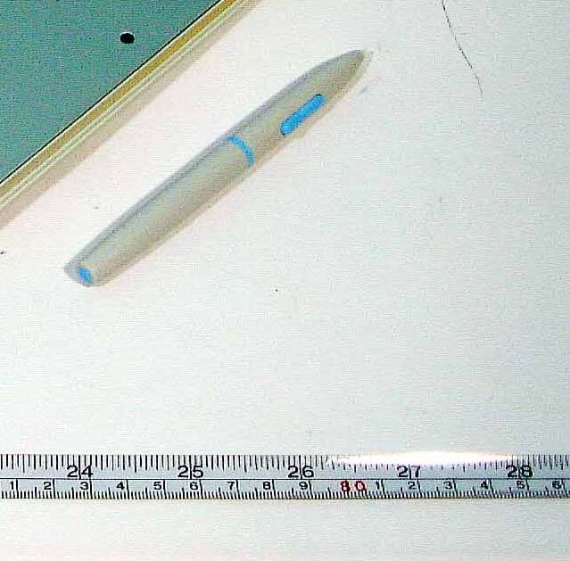
Click to zoom
Application Details
- Equipment Class
- DXX - Part 15 Low Power Communication Device Transmitter
- Date of Grant
- Nov 07, 2001
- Application Purpose
- Original Equipment
- Date of Application
- Nov 07, 2001
- Equipment Note
- Cordless Pen
- Frequency Range
- 0.23000000 - 0.27000000
- Country
- Taiwan
Documents & Files
Document Text
Text extracted from the exhibit documents filed with the FCC. Open a document above to read the original.
Users Manual
Pressure-Sensitive Pen Device FCC ID : M35UCWPENX User's Manual For IBM Personal Computers and Compatibles with Windows 95/98/ME/NT/2000 RS232C: Windows 95/98/ME/NT/2000 USB: Windows 98/ME/2000 Driver and Pen Utilities Version 3.5 The information contained in this document is subject to change without notice, and no part of this document may be reproduced or transferred in any form or by any means without the written consent of UC-Logic Technology Corporation. All trademarks referenced in this document belong to their respective owners. FEDERAL COMMUNICATIONS COMMISSION This device complies with Part 15 of the FCC Rules. Operation is subject to the following two conditions:(1) this device may not cause harmful interference, and (2) this device must accept any interference received, including interference that may cause undesired operation. NOTE This equipment has been tested and found to comply with the limits for a Class B digital device, pursuant to Part 15 of the FCC Rules. These limits are designed to provide reasonable protection. This equipment generates, uses and can radiated radio frequency energy and, if not installed and used in accordance with the instructions, may cause harmful interference to radio communications. However, there is no guarantee that interference will not occur in a particular installation If this equipment does cause harmful interference to radio or television reception, which can be determined by turning the equipment off and on, the user is encouraged to try to correct the interference by one or more of the following measures: -Reorient or relocate the receiving antenna. -Increase the separation between the equipment and receiver. -Connect the equipment into an outlet on a circuit different from that to which the receiver is connected. -Consult the dealer or an experienced radio/TV technician for help. Shielded interface cables must be used in order to comply with emission limits. Changes or modifications not expressly approved by the party responsible for compliance could void the user‘s authority to operate the equipment. General Information Overview Welcome to the world of pen-based computing! You will soon discover how easy it is to control the computer using a pen instead of a mouse. You will also be able to draw, sketch or paint on your computer as easily as you would on paper, using appropriate software such as PhotoImpact, PhotoShop, and Painter. Since all Pen Device models described in this manual are pressure-sensitive, you can choose to emulate a soft- tipped pen. This manual describes mainly how you install the Pen Device, configure it to best suit your use, and use Pen Utilities that come with the hardware. Specifically, it describes overall functions , items in the package, system requirements, hardware installation procedure, Driver and Pen Utilities installation procedure, verification of hardware installation, verification of overall installation, usage tips, pen scrolling, configuring the pen device, Annotate All program, Annotate for Word program, PenMail Program , and PenSigner Program. This manual is applicable to Driver and Pen Utilities Version 3.5. Note: For best results, please try to look at the screen while using the Pen, and avoid looking at Tablet Plate. See the section Usage Tips for more usage tips. Quick Start To start using your Pen Device quickly, take these steps: 1. Insert Driver Disc into an available CD-R drive, and the Setup program should start automatically. Press Enter key when the Setup message appears on the screen and let the program run its course. If the Setup program does not start automatically, you may start it manually by double tapping My Computer on Desktop, the CD-ROM drive icon , and then the Setup program icon . 2. Attach the hardware to your computer according to its type (Pen Device with USB Interface, Pen Tablet with RS232C Interface, or Tablet Keyboard with RS232C Interface). You have to power off your PC before attaching a Pen Device with RS232C interface. 3. Read Usage Tips . Start enjoying your Pen Device! Pen Device Functions Your Pen Device, when properly installed and all system requirements met, provides the following functions: 1. Direct Pointing - You can move the cursor to any spot on the screen by moving the Pen over Tablet Plate without touching the Plate. 2. Three-Button Mouse Commands - The Pen Device provides all functions of a three-button mouse with a Pen Tip and two Barrel Buttons, all programmable . 3. Scrolling documents or images - You can scroll up and down by moving the Pen freely over Tablet Plate (" Pen Scrolling ") without looking for the scroll bar. 4. Pen Launching - You can launch any application or emulate keyboard pressing by tapping on Hot Cells on Tablet Plate. 5. Adjusting the size and position of Pen Area on Tablet Plate. 6. Pressure Sensitivity - Allows the Pen to emulate various soft-tipped as well as hard-tipped pens. With the aid of Pen Utilities included in Driver Disc, the Pen Device provides the following functions: 1. Annotate for Word - Marking up Microsoft Word documents as if on a piece of paper, and storing the markups as part of the document. 2. Annotate All - Marking up any screen to send to someone on the Net or for later viewing. 3. PenMail - Writing a letter in your own handwriting and sending it through e- mail. 4. PenSigner - Capturing your online signature or simple hand drawing and inserting into various documents. With the aid of additional application programs, the Pen Device opens up even more possibilities: 1. Draw with emulated paint brushes, chalks, watercolor, and a host of other pens with programs such as Corel Painter Classic by Corel and PhotoImpact by Ulead . 2. Control your computer with the flip of your pen (known as "pen commands" or "gestures") with handwriting recognition programs such as Sensiva 2.0 by Sensiva . 3. Seal documents with your own signature with signature verification programs such as PenOp Signature by PenOp. 4.…
Text truncated - open the document above for the full version.
Block Diagram
P E N20 RS232 Cir c uit Funct i on Block Diagra m A n t e nna Se le c t ion c i r c uit Recei v e A n t e nna m o de l Signal A m plify c i r c uit Mi cr o Con t r o l Un i t Negative V o ltag e Gen e rator T o Computer Serial Port Level Co m p ar e Fi x e d C u r r e n t Gen e rator Y1 1 1.059432MH Z WP 8060U USB Cir c uit Funct i on Block Diagra m A n t e nna Se le c t ion c i r c uit Recei v e A n t e nna m o de l Signal A m plify c i r c uit Mi cr o Con t r o l Un i t Negative V o ltag e Gen e rator T o Computer USB Port Level Co m p ar e US B S eri al In terf ace E n gi n e Fi x e d C u r r e n t Gen e rator Y1 1 1.059432MH Z PEN06 Circuit Function Block Diagram B a t t e r 1 . 5 V Timer Counter For Suspend Wake up Feedback Oscillator Frequency Harass Oscillator coil magnetic field radiate 230270K 3
External Photos
FCC ID : M3 5 UCW P E N X FRONT SIDE OF EUT N u mber 1 142301- 01.jpg FCC ID : M3 5 UCW P E N X REA R SIDE OF EUT N u mber 2 142301- 02.jpg
ID Label/Location Info
EXHIBIT A. FCC ID LABEL FCC ID: M35UCWPENX The next page shows the location of FCC ID on EUT. FCC ID: M35UCWPENX 0.5CM 4CM The following statement will be placed in the User’s Manual. This device complies with Part 15 of the FCC Rules. Operation is subject to the following two conditions :(1) this device may not cause harmful interference, and (2) this device must accept any interference received, including interference that may cause undesired operation.
ID Label/Location Info
FCC ID: M35UCWPENX Label Location FCC ID
Internal Photos
FCC ID : M3 5 UCW P E N X M echanical C onst r uct i on N u mber 1 142301- 11.jpg FCC ID : M3 5 UCW P E N X R e a r s i d e o f M a i n B o a r d N u m b e r 2 152202- 12.jpg FCC ID : M3 5 UCW P E N X F r o n t s i d e o f M a i n B o a r d N u m b e r 3 142301- 14.jpg
Operational Description
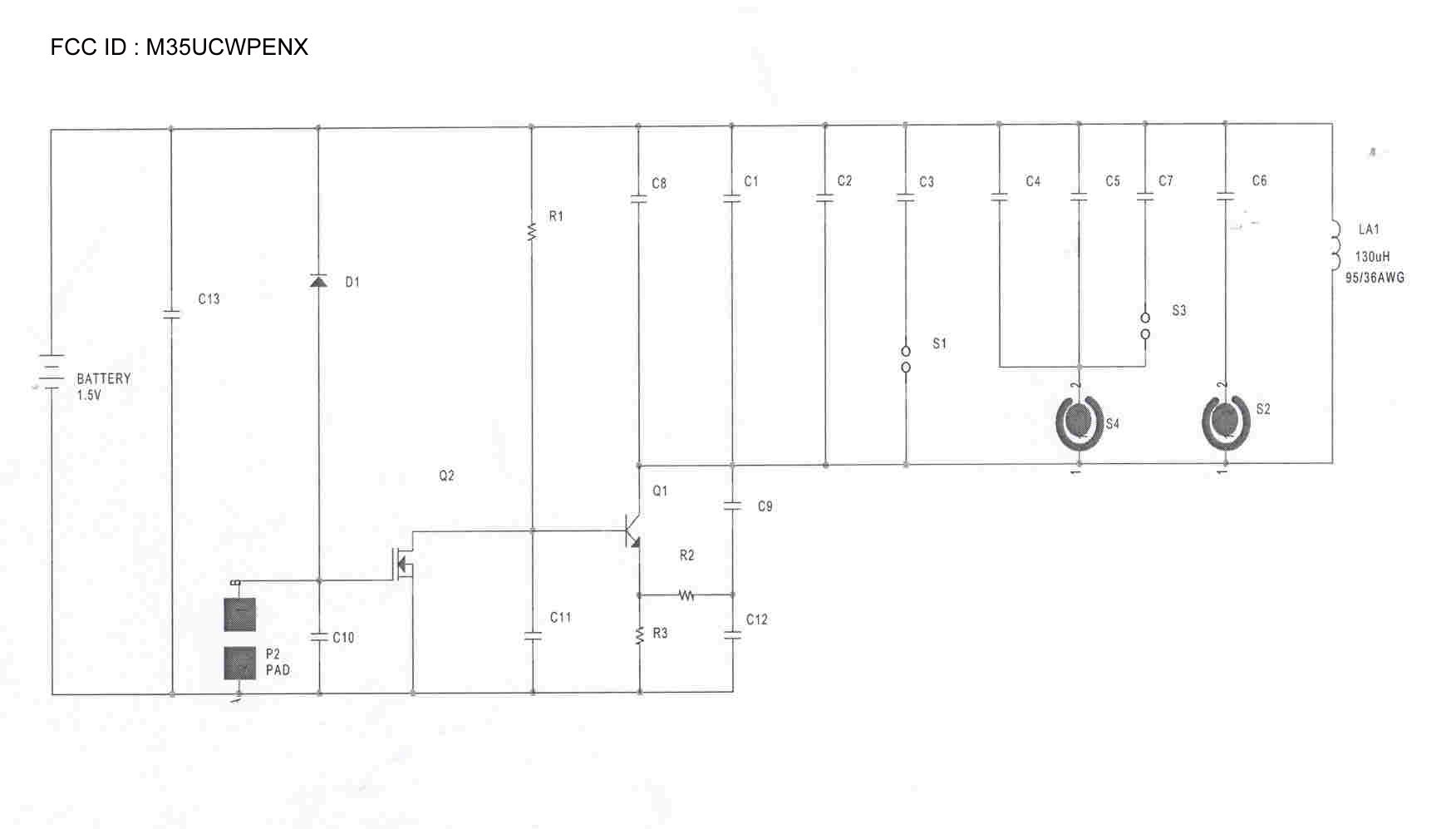
FCC ID : M35UCWPENX EMI of Wireless Pen Figure 1 below represents the working circuit in our wireless pen. In Figure 1, L1 is an oscillating component, whose function is similar to a location oscillator in a normal radio receiver or the horizontal oscillator in a TV receiver. The only difference is in its working frequency. R3 C4 I=120uA C2 L1 FIGURE 1 R1 BATTER 1.5V C3 R2 C1 Q1 The Component L1 is composed of a Ferrite rod (core), a ledge of coil, and a coil. See figure 2 below. Ferrite rod ledge of coil 96 turn coil Figure 2 Ferrite rod (core) in this circuit is used mainly for two functions: 1. Tuning: moving the ferrite rod adjusts the coil to required inductance value (L). When inductance value (L) is changed we get different frequency to decide the value of pressure. 2. EMI suppression: the ferrite rod (core) can suppress certain EMI transmissions. Figure 3 below depicts the working principles of our wireless pen. In working mode, the Wireless Pen operates like a magnet, with its magnetic force line going from the North Pole to the South Pole. By the nature of magnetic field, the line of magnetic force always form a closed loop. The energy level of magnetic force line will taper off along the distance in space. (This can be considered as a transformer with such a long distance between the input side and output side, it becomes non-conductive.) Figure 3 N S Tablet Wireless Pen When the wireless pen is working the line of magnetic force will induce a current on the grid of tablet, and the tablet can then use this induced current to determine the position of the pen. If we ignore the effect of the Ferrite Rod (It will reduce EMI), we can calculate the maximum intensity H of the magnetic field generated by the Wireless Pen as follows. H = (NI)/L = 96 x 120 uA/6mm = 1.92 uA/M = 0.00000192 A/M (MKSA), Where N = number of coil turns. I = current on coil, and L = length of from the beginning of the first coil turn to the end of the last coil turn. In conclusion the intensity of the induced magnetic field is less than 1.92 x 10 -7 , which is similar to a static magnetic field, and not a time-varying magnetic field. This, I believe, is why the lab could not detect the presence of a working Wireless Pen.
Test Report
FCC TEST REPORT Report No. : F142301 SPORTON International Inc. FCC ID : M35UCWPENX TEL : 886-2-2696-2468 Page No. : 1 of 19 FAX : 886-2-2696-2255 Issued Date : Nov. 06, 2001 FCC TEST REPORT for 47 CFR Part 15, Subpart C Equipment : Cordless Pen Model No. : PEN20 FCC ID : M35UCWPENX Filing Type : Certification Applicant : UC-LOGIC TECHNOLOGY CORP. 6F, No. 16, Lane 609, Sec. 5, Chung Hsing Rd., San-Chung City, Taipei, Taiwan, R.O.C. † The test result refers exclusively to the test presented test model / sample. † Without the written authorization of the test lab., the Test Report may not be copied. † Certificate or Test Report must not be used by the applicant to claim the product in this test report endorsement by NVLAP or any agency of U.S. government. SPORTON International Inc. 6F, No.106, Sec. 1, Hsin Tai Wu Rd., Hsi Chih, Taipei Hsien, Taiwan, R.O.C. FCC TEST REPORT Report No. : F142301 SPORTON International Inc. FCC ID : M35UCWPENX TEL : 886-2-2696-2468 Page No. : 2 of 19 FAX : 886-2-2696-2255 Issued Date : Nov. 06, 2001 Table of Contents CERTIFICATE OF COMPLIANCE...................................................................................................................................................3 1. General Description of Equipment under Test..................................................................................................................4 1.1. Applicant.......................................................................................................................................................................................4 1.2. Manufacturer.................................................................................................................................................................................4 1.3. Basic Description of Equipment under Test...................................................................................................................................4 1.4. Feature of Equipment under Test..................................................................................................................................................4 2. Test Configuration of Equipment under Test.....................................................................................................................5 2.1. Test Manner..................................................................................................................................................................................5 2.2. Description of Test System for Radiated Spurious emission test..................................................................................................5 2.3. Connection Diagram of Test System for Radiated Spurious emission test....................................................................................7 3. Test Software for Radiated Spurious emission test.......................................................................................................8 4. General Information of Test........................................................................................................................................................9 4.1. Test Facility...................................................................................................................................................................................9 4.2. Standard for Methods of Measurement.........................................................................................................................................9 4.3. Test in Compliance with................................................................................................................................................................9 4.4. Frequency Range Investigated......................................................................................................................................................9 4.5. Test Distance................................................................................................................................................................................9 5. Test of Radiated Emission (Spurious emission)............................................................................................................10 5.1. Major Measuring Instruments......................................................................................................................................................10 5.2. Test Procedures..........................................................................................................................................................................11 5.3. Typical Test Setup Layout of Radiated Emission........................................................................................................................12 5.4. Test Result of Radiated Emission (Spurious emission)...............................................................................................................13 6. Test of Radiated Emission (Fundamental emission)....................................................................................................14 6.1. Major Measuring Instruments......................................................................................................................................................14 6.2. Test Procedures.............................................................................................................................Error! Bookmark not defined. 6.3. Test Result of Radiated Emission (Fundamental emission)........................................................................................................15 7. Antenna Factor & Cable Loss for Radiated Spurious emission test....................................................................16 8. EMI Suppression Component List.........................................................................................................................................…
Text truncated - open the document above for the full version.
Test Setup Photos
FCC TEST REPORT Report No. : F142301 1.1. Photographs of Radiated Emission (Spurious) Test Configuration z The photographs show the configuration that generates the maximum emission. FRONT VIEW REAR VIEW SPORTON International Inc. FCC ID : M35UCWPEN TEL : 886-2-2696-2468 Page No. : 1 of 2 FAX : 886-2-2696-2255 Issued : Aug. 22, 2001 FCC TEST REPORT Report No. : F142301 1.2. Photographs of Radiated Emission (Fundamental) Test Configuration Because the fundamental emission , 255KHz, emitted by the EUT is too low to be measured at 3-meter test distance. The EUT was put at the center of the loop antenna to measure the fundamental emission. SPORTON International Inc. FCC ID : M35UCWPEN TEL : 886-2-2696-2468 Page No. : 2 of 2 FAX : 886-2-2696-2255 Issued : Aug. 22, 2001
Contact Information
Applicant
Joe Yu
Test Firm
SPORTON International IncKathy Lin
Technical Specifications
| # | Rule Parts | Frequency Range | Power Output |
|---|---|---|---|
| 1 | 15C | 0.23 MHz - 0.27 MHz | - |
Other Applications from UC-Logic Technology Co., Ltd.
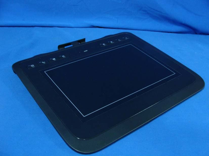
M35TWHL85
Jan 25, 2011WIRELESS TABLET
Equipment Class
DXX - Part 15 Low Power Communication Device Transmitter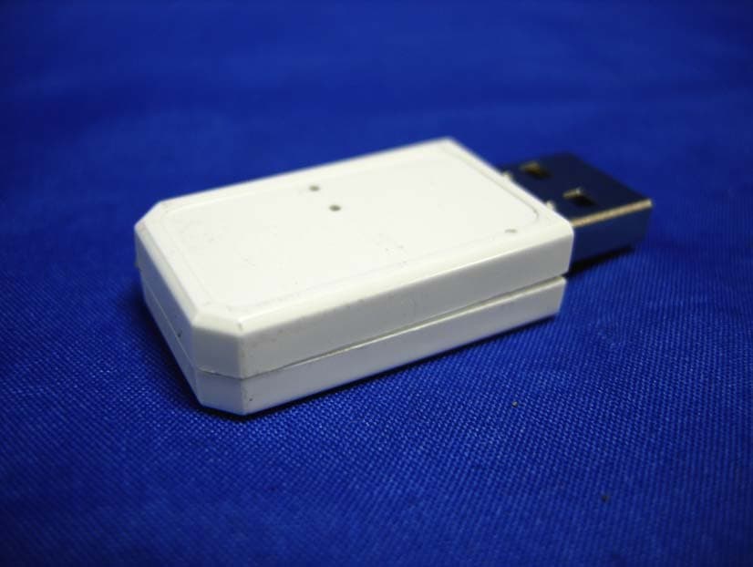
M35TWLR2
Mar 03, 2010USB WIRELESS DONGLE
Equipment Class
DXX - Part 15 Low Power Communication Device Transmitter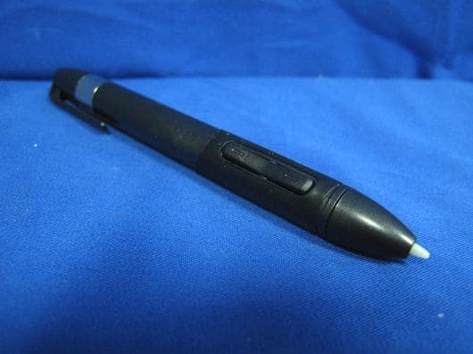
M35PEN2X
Mar 03, 2010WIRELESS PEN
Equipment Class
DCD - Part 15 Low Power Transmitter Below 1705 kHzM35UCSP33S
Aug 24, 1997JBP - Part 15 Class B Computing Device Peripheral
Equipment Class
JBP - Part 15 Class B Computing Device PeripheralM35UCSP64S
Jan 06, 1997Digitizing Table w/Intentional Radiator
Equipment Class
DCD - Part 15 Low Power Transmitter Below 1705 kHz