M4ZID6200IDentity 6204 (900 MHz) RFID Reader
3M Traffic Safety Systems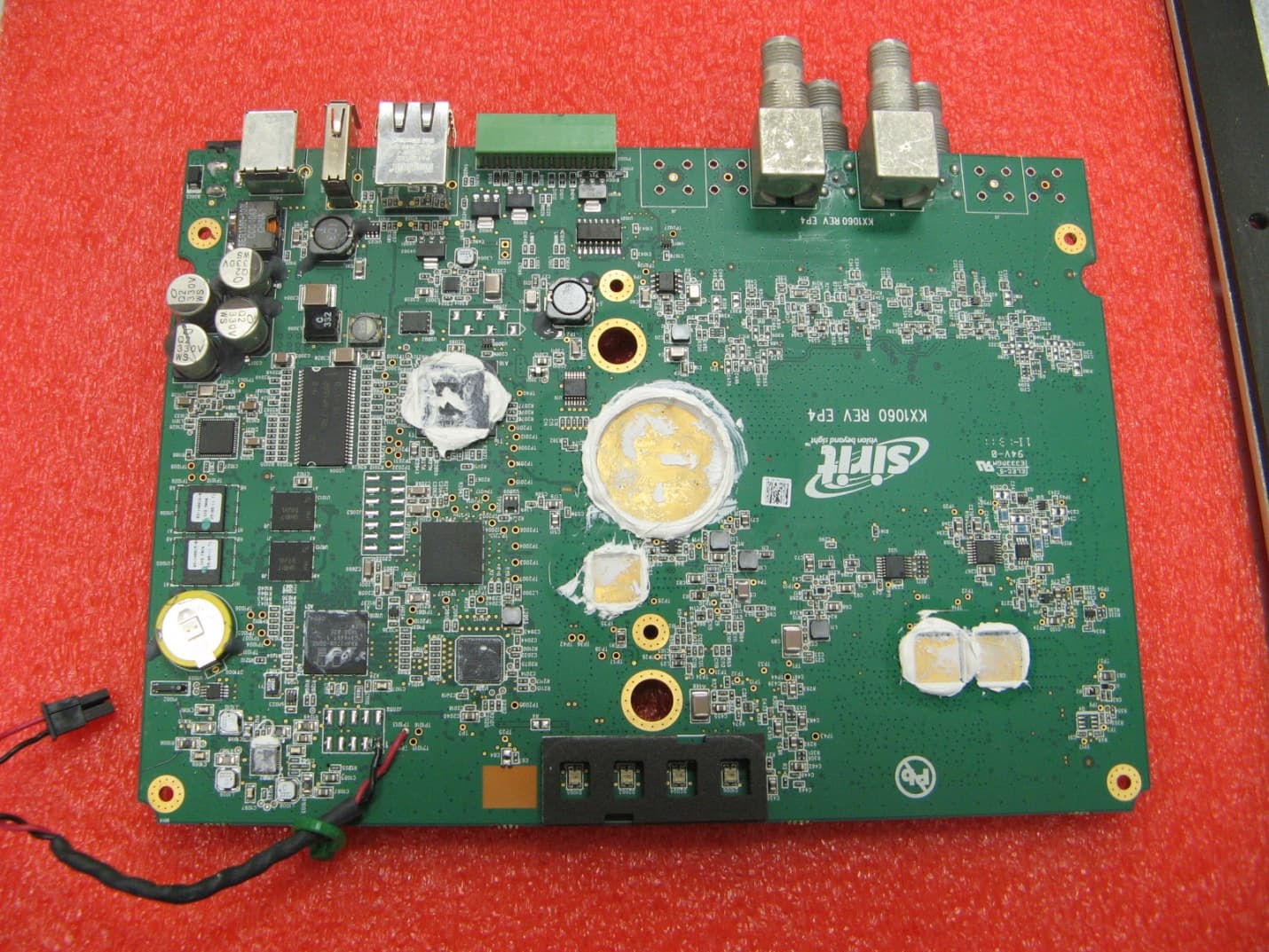
Click to zoom
Application Details
- Equipment Class
- LMS - Part 90 Location & Monitoring Transmitter
- Date of Grant
- Jan 29, 2012
- Application Purpose
- Original Equipment
- Date of Application
- Jan 26, 2012
- Equipment Note
- IDentity 6204 (900 MHz) RFID Reader
- Frequency Range
- 914.25000000 - 915.75000000
- Company
- 3M Traffic Safety Systems
- Country
- United States
Documents & Files
Document Text
Text extracted from the exhibit documents filed with the FCC. Open a document above to read the original.
Users Manual
IDentity 6204 USER’s GUIDE V1.02 January 26, 2012 © 2012 Sirit Inc., All Rights Reserved. “Sirit”, the Sirit Design, “RFID by Sirit”, the RFID by Sirit Design and “vision beyond sight” are all trademarks of Sirit Inc. All other trademarks are the property of their respective owners. Specifications are subject to change without notice. This product is covered by one or more of the following patents: U.S. Patent No. 7,199,713, 7,209,040, 6,346,881, and 6,617,962. Disclaimer and Limitation of Liability The content of this manual is for information use only and is subject to change without notice. Sirit assumes no responsibility or liability for any errors or inaccuracies that may appear in this publication. No part of this manual may be reproduced in any form or by any means, electronic, mechanical, recording, or otherwise, without the prior written permission of Sirit. Sirit products are not designed, intended, authorized or warranted to be suitable for life support applications or any other life critical applications which could involve potential risk of death, personal injury, property damage, or environmental damage. FCC Notice This equipment has been tested and found to comply with the limits for a Class B digital device, pursuant to Part 15 of the FCC Rules. These limits are designed to provide reasonable protection against harmful interference in a residential installation. This equipment generates, uses, and can radiate radio frequency energy and, if not installed and used in accordance with the instructions, may cause harmful interference to radio communications. However, there is no guarantee that interference will not occur in a particular installation. If this equipment does cause harmful interference to radio or television reception, which can be determined by turning the equipment off and on, the user is encouraged to try to correct the interference by one or more of the following measures: • Reorient or relocate the receiving antenna. • Increase the separation between the equipment and receiver. • Connect the equipment into an outlet on a circuit different from that to which the receiver is connected. • Consult FSTech-Sirit or an experienced radio/TV technician for help. Le présent appareil est conforme aux CNR d'Industrie Canada applicables aux appareils radio exempts de licence. L'exploitation est autorisée aux deux conditions suivantes : (1) l'appareil ne doit pas produire de brouillage, et (2) l'utilisateur de l'appareil doit accepter tout brouillage radioélectrique subi, même si le brouillage est susceptible d'en compromettre le fonctionnement. This Class B digital apparatus complies with Canadian ICES-003. Cet appareil numérique de la classe B est conforme à la norme NMB-003 du Canada. About Sirit, a Federal Signal Technologies Company Sirit, a Federal Signals Technologies Company, designs, develops, manufactures and sells Radio Frequency Identification (RFID) technology. Targeted at a diverse set of markets RFID technology has become a core technology for applications including: electronic toll collection, access control, cashless payment systems, product identification, and supply chain management systems including logistics, warehousing and manufacturing, and asset management. Federal Signal Technologies 2 Technology Irvine, CA 92618 Tel: (949) 341-0409 Fax (949) 341-0521 Web: www.fstech.com Sirit 1321 Valwood Parkway, Suite 620 Carrollton, Texas 75006 United States Tel: 972.243.7208 Fax: 972.243.8034 Toll Free: 1.866.338.9586 Web: www.sirit.com Preface IDentity 6204 User’s Guide i Preface Intended audience This document is intended for those who wish to setup and operate the IDentity 6204 Radio Frequency Identification system. Before attempting to install, configure, and operate this product, you should be familiar with the following: h Windows-based software installation and operation h Device communication parameters including Ethernet and serial communications h RFID reader configuration including antenna placement h Basic digital input/output control What’s in this guide The information in this guide is presented as follows: Chapter 1 - Reader Overview:This chapter provides a brief overview of the IDentity 6204 hardware and software. Chapter 2 - Reader Equipment Installation – This chapter describes how to mechanically and electrically install the reader. Chapter 3 - Reader Startup Tool (RST) Software Installation – This chapter describes how to install the Microsoft Windows RST application. Chapter 4 - Reader Operation – This chapter describes how to initially test a reader and how to operate deployed readers. Chapter 5 - Reader Startup Tool (RST) – This chapter describes the RST and the various functions you can perform with this Microsoft Windows application. Chapter 6 - Reader Configuration Tool (RCT) – This chapter describes the RCT and the various functions you can perform with this embedded reader application. Chapter 7 - Configuring Digital Inputs and Outputs – This chapter describes how to setup the reader’s digital inputs and outputs. Chapter 8 - Specifications – This chapter detailed mechanical, electrical, and environmental specifications for the IDentity 6204. Chapter 9 - Safety Instructions – This chapter provides important safety information about the IDentity 6204. All users must read this section before installing or operating this reader. Appendix A – Error Handling – This appendix lists IDentity 6204 errors and warnings. Corrective actions are provided where applicable. ii IDentity 6204 User’s Guide What’s New in this Version Version 1.0 of this User’s Guide is the first release. Conventions used in this manual The following conventions are used in this manual: Bold courier font indicates code entered by the user (values) within parentheses indicate parameters (values) in italics indicate user defined variables. <n> indicates a variable number used in a function that can apply to several different devices such as antennas or I/O ports. WARNING…
Text truncated - open the document above for the full version.
Cover Letter(s)
Sirit Technologies Inc. Tel: 972.243.7208 1321 Valwood Parkway, Suite 620 Toll Free: 877.492.0101 Carrollton, Texas Fax: 972.243.8034 75006 USA Web site: www.sirit.com December 16, 2011 Nemko Canada Inc. 303 River Road Ottawa, Ontario, Canada K1V 1H2 FCC ID: M4ZID6200 Product Name: ID6204 Request for Confidentiality Pursuant to Sections 0.457 and 0.459 of the commission rules, we hereby request that the following documents be held confidential: • ID6204 Schematics • ID6204 Block Diagrams • Bill of Materials • ID6204 Operational Description These materials contain trade secrets and proprietary information and are not customarily released to the public. The public disclosure of this information might be harmful to the company and provide unjustified benefits to our competitors. Dated this 16th Day of December 20 11 By: Randal Roebuck Signature Printed Title: Director of DSRC Interoperability, Regulations & Connected Vehicles On behalf of : Sirit Technologies Inc. Telephone: 972-243-7208 x 2123
Cover Letter(s)
Sirit Technologies Inc. Tel: 972.243.7208 1321 Valwood Parkway, Suite 620 Toll Free: 877.492.0101 Carrollton, Texas Fax: 972.243.8034 75006 USA Web site: www.sirit.com December 22, 2011 Nemko Canada Inc 303 River Road Ottawa, Ontario, Canada K1V 1H2 Attn: Director of Certification Authority to Act as Agent FCC On our behalf, I appoint Zarah MacIvor, Nemko USA, Inc. at 802 N Kealy Avenue, Lewisville TX 75057 to act as our agent in the preparation of this application for equipment certification. I certify that submitted documents properly describe the device or system for which equipment certification is sought. I also certify that each unit manufactured, imported or marketed, as defined in FCC regulations will have affixed to it a label identical to that submitted for approval with this application. In signing this letter, Applicant certifies that neither the applicant nor any party to the application is not subject to a denial of Federal benefits, that include FCC benefits, pursuant to Section 5301 of the Anti-Drug Abuse Act of 1988, 21 U.S.C. § 862 because of a conviction for possession or distribution of a controlled substance. See 47 CFR 1.2002(b) for the definition of a "party" for these purposes. For instances where our authorized agent signs the application for certification on our behalf, I acknowledge that all responsibility for complying with the terms and conditions for certification, as specified by Nemko Canada Inc, still resides with Sirit Technologies Inc., 1321 Valwood Parkway, Suite 620, Carrollton, TX 75006-8398, USA. Dated this 22th Day of December 20 11 Agency agreement expiration date: 31 December 2012 By: Randal Roebuck Signature Printed Title: Director of DSRC Interoperability, Regulations & Connected Vehicles On behalf of : Sirit Technologies Inc. Telephone: 972-243-7208 x 2123
ID Label/Location Info
ID6204 FCC Label Location
Internal Photos
ID6204 Chassis Interior ID6204 Chassis Interior ID6204 Bottom Shield Cover, Heater Control PCB, Thermostat & Interconnect Wiring Heater Control PCB Top Heater Control PCB Bottom ID6204 Bottom Shield Cover, Close Up ID6204 PCB Bottom (Bottom Shield Cover Removed) ID6204 Bottom Shield Cover Interior ID6204 PCB Top ID6204 Top Shield Cover Interior
Parts List/Tune Up Info
- 1 - Sirit Technologies Inc. Tel: 972.243.7208 1321 Valwood Parkway, Suite 620 Toll Free: 877.492.0101 Carrollton, Texas Fax: 972.243.8034 75006 USA Web site: www.sirit.com January 20, 2012 Nemko Canada Inc 303 River Road Ottawa, Ontario, Canada K1V 1H2 Attn: Director of Certification Re: IDentity 6204 Part 90 Transceiver Tuning Procedure We believe it is not necessary to produce a separate tuning procedure document for Part 90 operation of the IDentity 6204 (ID 6204) RFID Transceiver for the following reasons: • The maximum antenna port transmitter RF power is limited under factory installed software to 2 W (33 dBm) for the Title 21 protocol & is currently limited to 2W (33 dBm) for all other modulated protocols. The user can only lower the maximum modulated transmitter power. No increase beyond the limits stated above is permitted. The RF output power is adjustable in 0.1 dB steps to 1 mW (0 dBm), with a practical lower limit of 10 mW (10 dBm). • The antenna gain and RF cable loss parameters are factory set to limit the total system radiated power to 30 Watts ERP when the antenna and RF cable is provided by Sirit. When the reader is professionally installed these parameters are user adjustable. The ID6204 User’s Guide contains a cautionary note instructing the professional installer on how to verify compliance with the 30 W (ERP) limit based on the antenna gain and RF cable loss. The installer must also declare the operational ERP of the reader system for the FCC or Industry Canada Site License. Sirit application engineers are available to assist with the reader configuration, if needed, through our customer support operation. • The ISO 18000-6C (C1G2) baseband transmitter data rate is user selectable for 40, 80 or 160 kbps. The factory installed software limits the operating frequency for the C1G2 protocol to 902.75 through 903.25 MHz and 911.2 through 920.45 MHz. The transceiver has been certified to be compliant with all Part 90 requirements when operating within this frequency range with the worst case (highest occupied bandwidth) baseband data rate of 160 kbps. • The factory installed software limits the Title 21 protocol’s operating frequency range to 911.7 through 919.95 MHz. The user is not permitted to adjust the operating frequency for this protocol outside of this range. The transceiver has - 2 - Sirit Technologies Inc. Tel: 972.243.7208 1321 Valwood Parkway, Suite 620 Toll Free: 877.492.0101 Carrollton, Texas Fax: 972.243.8034 75006 USA Web site: www.sirit.com been certified to be compliant with all Part 90 requirements when operating within this frequency range. • The factory installed software limits the PS111 protocol’s operating frequency range to 914.25 through 915.75 MHz. The user is not permitted to adjust the operating frequency for this protocol outside of this range. The transceiver has been certified to be compliant with all Part 90 requirements when operating within this frequency range. Sincerely, David Missimer VP of Engineering, Sirit
RF Exposure Info
Prediction of MPE limit at a given distance Equation from page 18 of OET Bulletin 65, Edition 97-01 where:S = power density P = power input to the antenna G = power gain of the antenna in the direction of interest relative to an isotropic radiator R = distance to the center of radiation of the antenna Maximum peak output power at antenna input terminal:35.00(dBm)* Maximum peak output power at antenna input terminal:3162.27766(mW) Antenna gain(maximum):12(dBi)* Maximum antenna gain:15.84893192(numeric) Time Averaging:100(%)* Prediction distance:100(cm)* Prediction frequency:915(MHz)* MPE limit for uncontrolled exposure at prediction frequency:0.610(mW/cm^2) Power density at prediction frequency:0.398832 (mW/cm^2) This equates to:3.988321282 W/m^2 2 4R PG S
Test Report
Nemko Test Report: 10215672 Part 90 trf Applicant: Sirit Corporation 1321 Valwood Parkway Carrollton, TX 75006 Equipment Under Test: ID6204 (E.U.T.) FCC Identifier: M4ZID6200 In Accordance With: FCC Part 90, Subpart I LMS Transmitter Tested By: Nemko USA Inc. 802 N. Kealy Lewisville, Texas 75057-3136 TESTED BY: DATE: 3-5 December 2011 David Light, Senior Wireless Engineer APPROVED BY: DATE: 5-Jan-2011 Mike Cantwell, GM Total Number of Pages: 40 Nemko USA FCC PART 90, SUBPART I Fixed Transmitter EQUIPMENT:ID6204 PROJECT NO.: 10215672RUS1 Page 2 of 40 Table of Contents SECTION 1. SUMMARY OF TEST RESULTS 3 SECTION 2. GENERAL EQUIPMENT SPECIFICATION 5 SECTION 3. RF POWER OUTPUT 7 SECTION 4. OCCUPIED BANDWIDTH 9 SECTION 5. SPURIOUS EMISSIONS AT ANTENNA TERMINALS 15 SECTION 6. FIELD STRENGTH OF SPURIOUS EMISSIONS 24 SECTION 7. FREQUENCY STABILITY 28 SECTION 8. TEST EQUIPMENT LIST 30 ANNEX A - TEST METHODOLOGIES 31 ANNEX B - TEST DIAGRAMS 37 Nemko USA FCC PART 90, SUBPART I Fixed Transmitter EQUIPMENT:ID6204 PROJECT NO.: 10215672RUS1 Page 3 of 40 Section 1. Summary of Test Results Manufacturer: Sirit Corporation Model No.: ID6204 Serial No.: 96FC8402008C0C4B Firmware Rev.: 0.2.19003 General: All measurements are traceable to national standards. These tests were conducted on a sample of the equipment for the purpose of demonstrating compliance with FCC Part 90, Subpart I. New Submission Production Unit Class II Permissive Change Pre-Production Unit THIS TEST REPORT RELATES ONLY TO THE ITEM(S) TESTED. THE FOLLOWING DEVIATIONS FROM, ADDITIONS TO, OR EXCLUSIONS FROM THE TEST SPECIFICATIONS HAVE BEEN MADE. NONE See “Summary of Test Data”. Nemko USA Inc. authorizes the above named company to reproduce this report provided it is reproduced in its entirety and for use by the company’s employees only. Any use which a third party makes of this report, or any reliance on or decisions to be made based on it, are the responsibility of such third parties. Nemko USA Inc. accepts no responsibility for damages, if any, suffered by any third party as a result of decisions made or actions based on this report. This report applies only to the items tested. Nemko USA FCC PART 90, SUBPART I Fixed Transmitter EQUIPMENT:ID6204 PROJECT NO.: 10215672RUS1 Page 4 of 40 Summary Of Test Data NAME OF TEST PARA. NO. SPEC. RESULT RF Power Output 90.205 30 Watts ERP Complies Audio Frequency Response TIA EIA- 603.3.2.6 N/A N/A Audio Low-Pass Filter Response TIA EIA- 603.3.2.6 N/A N/A Modulation Limiting TIA EIA- 603.3.2.6 N/A N/A Occupied Bandwidth 90.210 Plots Complies Spurious Emissions at Antenna Terminals 90.210 Plots Complies Field Strength of Spurious Emissions 90.210 -25 dBm Complies Frequency Stability 90.213 Transient Frequency Behavior 90.214 N/A N/A Footnotes: (1) The radio does not support audio modulation. (2) Fixed non-multilateration transmitters with an authorized bandwidth that is more than 40 kHz from the band edge are not subject to frequency stability restrictions. The device however was measured to show compliance to Part 2 requirements. Nemko USA FCC PART 90, SUBPART I Fixed Transmitter EQUIPMENT:ID6204 PROJECT NO.: 10215672RUS1 Page 5 of 40 Section 2. General Equipment Specification Transmitter Supply Voltage Input: 120 Vac Frequency Range: 902.00 to 904.00 MHz Band 1 909.75 to 921.75 MHz Band 2 Tunable Bands: 902.75 to 903.25 MHz Band 1 911.20 to 920.45 MHz Band 2 Type(s) of Modulation: F3E (Voice) F1D F2D D7W (QAM) Other K1D Output Impedance: 50 ohms Operator Selection of Operating Frequency: Software controlled Power Output Adjustment Capability: Software controlled Nemko USA FCC PART 90, SUBPART I Fixed Transmitter EQUIPMENT:ID6204 PROJECT NO.: 10215672RUS1 Page 6 of 40 Description of EUT ID6204 is a 900 MHz RFID reader operating in the non-multilateral services. The IDentity 6204 is equipped with four 50 Ohm RFID antenna ports. Only one port is active at any given time. System Diagram ID 6204 Power Supply RFID Tag AC Mains Nemko USA FCC PART 90, SUBPART I Fixed Transmitter EQUIPMENT:ID6204 PROJECT NO.: 10215672RUS1 Page 7 of 40 Section 3. RF Power Output NAME OF TEST: RF Power Output PARA. NO.: 90.205 TESTED BY: D. Light DATE: 3 December 2011 Test Results: Complies. Measurement Data: C1G2 modulation 902.75 – 903.25 MHz Frequency (MHz) Measured Power (dBm) Measured Power (Watts) 902.75 34.8 3.0 903.25 34.9 3.1 C1G2 modulation 911.2 – 920.45 MHz Frequency (MHz) Measured Power (dBm) Measured Power (Watts) 911.20 35.0 3.2 920.45 35.0 3.2 Title 21 modulation 911.7 – 919.95 MHz Frequency (MHz) Measured Power (dBm) Measured Power (Watts) 911.70 32.9 2.0 919.95 33.0 2.0 PS111 modulation 914.25 – 915.75 MHz Frequency (MHz) Measured Power (dBm) Measured Power (Watts) 914.25 35.0 3.2 915.75 34.9 3.1 The rf power output level must be adjusted when using antennas with gain in order to insure that the radio does not transmit above the 30 watt erp limit. The installer is advised in the User Guide to set the antenna gain and cable loss in the installation software. The reader is then automatically set to the appropriate power output level. As supplied the reader can only achieve a maximum of 2 watts rf power at the reader output port. For the purposes of this testing a special manufacturer access code was Nemko USA FCC PART 90, SUBPART I Fixed Transmitter EQUIPMENT:ID6204 PROJECT NO.: 10215672RUS1 Page 8 of 40 used to adjust the power to the absolute maximum as this gives the worst-case measurement results. Test Equipment Used: 1464 -1627-1474 Test Conditions: Temperature: 23 O C Relative Humidity: 36% Spectrum analyzer settings: RBW: 3 MHz VBW 3 MHz Detector: Peak Sweep time: Auto Nemko USA FCC PART 90, SUBPART I Fixed Transmitter EQUIPMENT:ID6204 PROJECT NO.: 10215672RUS1 Page 9 of 40 Section 4. Occupied Bandwidth NAME OF TEST: Occupied Bandwidth PARA. NO.: 90.210 TESTED BY: D. Light DATE: 3 December 2011 Test Results: Complies. Test Data: See attached graph(s). Test Equipment Used: 1464 -1627-1474 Test Conditions:…
Text truncated - open the document above for the full version.
Contact Information
Applicant
Randal D. Roebuck(Manager, RFID Regulatory)
Technical Contact
Sirit Technologies, Inc.Randal Roebuck
[email protected]972-243-7208
1321 Valwood Parkway, Suite 620 · Carrollton · United States
Non-Technical Contact
Nemko USA, Inc.Zarah G MacIvor
[email protected]214-629-5683
Test Firm
Nemko Dallas, Inc.Mike Cantwell
Technical Specifications
| # | Rule Parts | Frequency Range | Power Output | Emission | Tolerance |
|---|---|---|---|---|---|
| 4 | 90.353 | 914.25 MHz - 915.75 MHz | 3 W | 1M66K1D | 1 ppm |
Other Applications from 3M Traffic Safety Systems
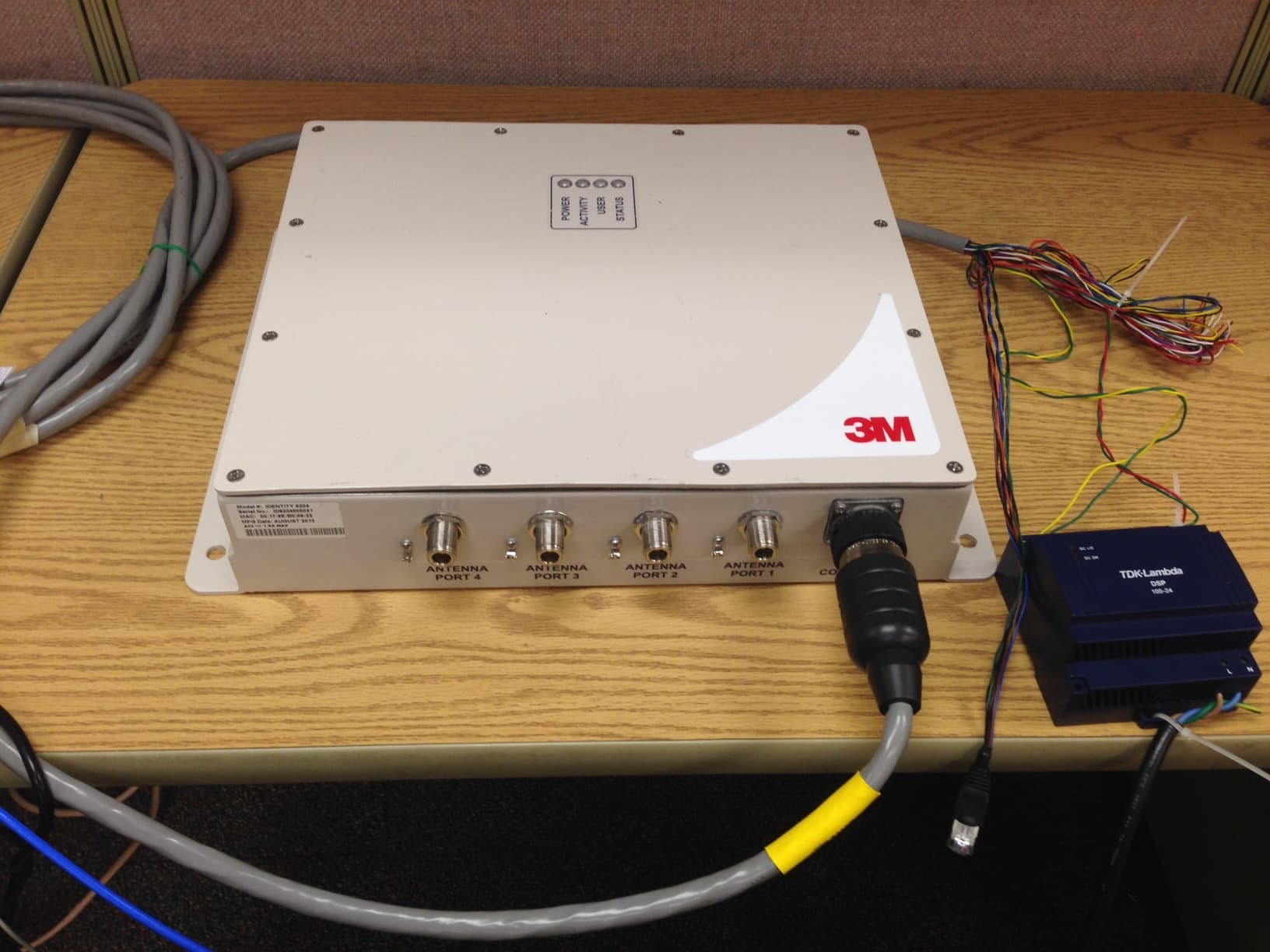
M4Z6204
Dec 03, 20143M UHF RFID Reader
Equipment Class
DSS - Part 15 Spread Spectrum Transmitter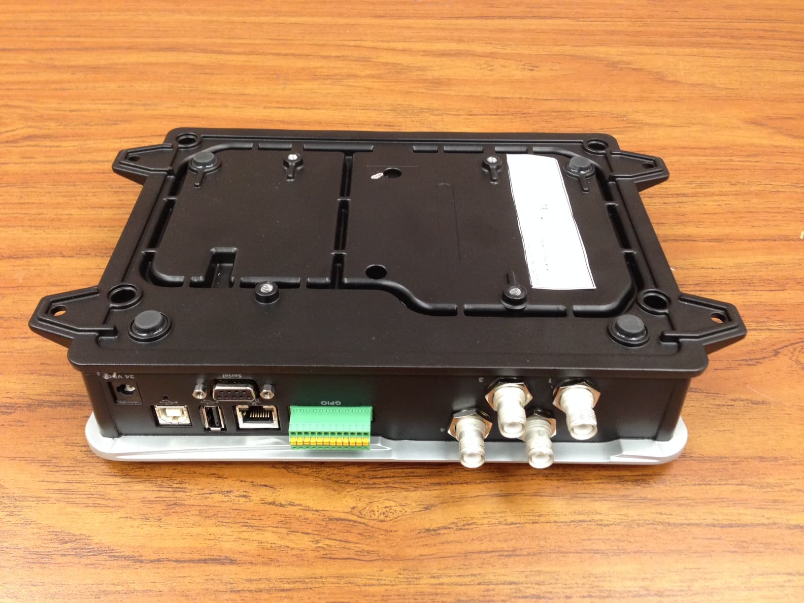
M4Z1000
Oct 13, 20143M Compact RFID Reader
Equipment Class
DSS - Part 15 Spread Spectrum Transmitter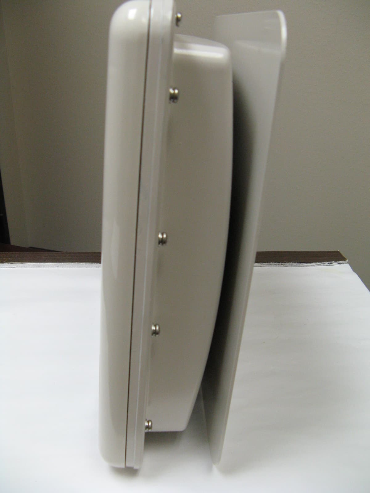
M4ZID4100-90
Apr 17, 2012IDentity 4100-90 RFID Reader
Equipment Class
LMS - Part 90 Location & Monitoring Transmitter
M4ZIN610
Oct 05, 2011Infinity 610
Equipment Class
DSS - Part 15 Spread Spectrum Transmitter
M4ZIDMAX019
Nov 18, 2008Identity Max Desktop Reader
Equipment Class
DSS - Part 15 Spread Spectrum Transmitter