M5U-101-460CPrivate address wireless network PAWN 101-460C
Head Connection Systems Ltd
Click to zoom
Application Details
- Equipment Class
- TNB - Licensed Non-Broadcast Station Transmitter
- Date of Grant
- May 08, 2000
- Application Purpose
- Original Equipment
- Date of Application
- Mar 27, 2000
- Equipment Note
- Private address wireless network PAWN 101-460C
- Frequency Range
- 450.00000000 - 470.00000000
- Company
- Head Connection Systems Ltd
- Country
- Israel
Documents & Files
Document Text
Text extracted from the exhibit documents filed with the FCC. Open a document above to read the original.
Users Manual
Private Address Wireless Network Two Way Communications for Extreme Noise Environment MODEL 460C OPERATING MANUAL Thank you for buying this HCS transceiver. This instruction manual contains important safety and operating instruction. Please read it carefully before using the Headset. HEAD CONNECTION SYSTEMS LTd. 112 Soundview Drive, Port Washington NY, 11050 – 1750 Fax: (516) 944-7556 For Extreme Noise Environment HCS Head Connection Systems Ltd . 2 1. Model-460C was tested and approved according the FCC part 90 for Programmable UHF commercial licence - FCC ID: M5U-101-460C GENERAL DESCRIPTION Two-way Programmable radio headsets (earmuffs), up to 4 frequencies, UHF (450-470MHz) transceiver, Ni-HM rechargeable battery operated, built into a highly efficient hearing protection for secure voice communications in noisy environments. Built in connector for Sell- phone / music plug or frequencies program cable. FUNCTIONALITY Enables wireless communication between all headsets and with an optional base-station on common frequencies. The noise-suppressing microphone efficiently reduces background noise. The headset microphone and speakers are used simultaneously with a connected cellular phone. Transmission can be initiated by manually push-to-talk or hands free VOX system. APPLICATIONS The applications for PAWN are many; Shop floors, Power plants, Forestry, Construction sites, Quarries, Recreational areas and other noisy areas where secure communication over short distances are essential. The plug-in sell-phone enables clear communication with the outside world. OPERATING INSTRUCTIONS Simplified controls make PAWN Headsets easy to use. A four-position switch selects the operating mode, either VOX /PTT or PTT. Rotary switch controls On/Off/Volume. 2. PRODUCT LAYOUT 1. PTT - ”talk” button for manual transmission 2. Program /cell phone Plug-in. 3. 4-way switch-VOX/PTT setting with three alternatives for adjusting VOX circuit’s sensitivity, to ensure "Hands-Free" correct microphone activation in relation to external noise levels. The PTT position, is activated via the ”talk” button. 4. Volume On/Off control for adjusting the volume level in the headset. 5. Frequency setting, - Two -position pre-set channels. 6. Charging socket. 1 3 2 5 4 6 3 3. Transmitting and receiving: The headset is in receiving mode, when turned ON by the Volume/ On/Off switch. To transmit voice, make sure that the microphone is very close to your mouth (about ½ “) and the white dot on the microphone is against your mouth. Push the PTT button or adjust the VOX sensitivity and start talking. After releasing the PTT or when you stop talking in VOX mode, you and all other recipients will hear a beep tone- to confirm end of transmission. 4. Adjustment of the VOX sensitivity: A. Maximum sensitivity (first VOX level - opposite to the PTT position) is appropriate for communication in low noise levels - up to 92dB(A). B. Medium sensitivity starts the VOX with this position. Suitable for most noisy area up to 105dB(A). C. Minimum sensitivity (lowest sensitivity- position close to the PTT position) is appropriate for transmissions in high noise levels (up to 130dB and requires an increased voice signal in order to activate the transmitter. Note: When transmitting, you should hear your own voice through the speakers. 5. Suggestions for proper operation: A. It is recommended to use the PTT to transmit if you have a free hand.. B. When using VOX mode, speak continuously and avoid silent periods between words. C. When you receive a transmission, the PAWN blocks VOX transmission, PTT is always available. 6. Should the transmitter not work properly in VOX mode check the following: A. Is the VOX sensitivity position is right for the noise surrounding you? B. Is the microphone positioned close enough to your mouth? C. Are you speaking loudly enough? D. Is the other user transmitting, or is the VOX sensitivity set so high that the transmitter is constantly activated? 7. CTCSS tone (PL Decoder/Encoder) considerations: A. The default internal dip switch position is OFF. B. If you experience interference on the selected channel, it is recommended to change the channel. If you must stay on the first channel, you move the CTCSS dip switch to ON. C. Please note: D. If you are using the VOX system with PL, expect a longer delay between beginning of speech and transmission than by using PTT. The recessives will have a delay of 1-2 seconds. There for you must extend the first word like - DDDDDDave, listen..... E. Every body must change to CTCSS ON in order for this feature to work because it affects all channels. 4 8. BATTERY MAINTENANCE AND CHARGING PROCEDURE Important: Before first use charge the battery for 15 hours. Always charge with power turned off. To save battery power, the unit is programmed to self shut-off within 60 min. if no activity, receiving or transmitting is detected. A chirp tone will be heard 30 second before shutdown. When the battery is almost empty, A number of alert short tone beep will be heard before shutdown, and the red LED light will blink. Important: For best functionality, remove hair around the ears from under the cushions to improve the acoustical seal against the head. Eyeglass temples should be as thin as possible and conform close to the head. Turn on the headset and adjust the volume for best listening level. 10. HEADSET MAINTENANCE AND USER INFORMATION In order to fully benefit from the superior noise attenuation, wear PAWN 100% of the time you are exposed to noise! Regularly clean the outside of PAWN using warm water and a mild detergent. WARNING: The unit must not be submerged in water. Do not store or place PAWN in temperatures exceeding +55 C (13O F). Do not place the unit behind a car windshield or in direct sunlight. Certain chemicals may negatively effect this product. The manufacturer can provide further information. PAWN and especially the cushions may degrade over time and should be examined regularly to v…
Text truncated - open the document above for the full version.
Block Diagram
- HEAD CONNECTION LTD. - ASSEMBLY SCHEMATICS OUTSIDE430.DSN0 PAWN460- EXTERNAL WIRING A 11Sunday, March 28, 1999 HEAD CONNECTION SYSTEMS LTD. Title SizeDocument NumberRev Date:Sheet of CHANNEL SELECT VOX SELECT PAWN400 REV 0 CARD LEFT CUP RIGHT CUP BROWN RED VIOLET BLACK DARK RED PINK DARK BROWN YELLOW GREEN WHITE PURPLE GRAY WHITE BLUE YELOW GRAY PINK WHITE GREEN YELLOW DARK BROWN PINK DARK RED BROWN BRIDGE SOLDER x10 CABLE SHILDED 6 WIRE LiYD11Y 0033 206 R+T SHIELD VIOLETBLACK Shield VOX1 VOX2 VOX3 VOX_SENSE SP16 +BAT GREEN GREEN GREEN 9 SP12 CH_B SP10 RED RED PURPLE 11 BLUE BLUE BLUE 14 BLACK BROWN BROWN 1 BLACK BLACK GRAY 12 BROWNSP14 SPKR+ SPKR- SP15 4 MIC 3 MICG LED RED RED 2 CH_A SP9 WHITE WHITE WHITE 10 WHITE 13 WHITE PTT SP4 SP3SP7 SP8 SP5 SP11 SP6 SP13 SP17 D3 3MM RED LED D3 BAT-65 ANT1 ALINCO/ EA0050A SW4 C&K MB04-L1NZQ A 1 2 3 4 6 7 8 9 B SW3 C&K/ MB04-L1NZQ A 1 2 3 4 6 7 8 9 B J3 ORBITEC/ OR775550 + - MIC1 ELECOM/ MFD-68 + - LS2 ELECOM/4025FK6E + - R102 20/ 0.2Watt BT1 PANASONIC/ Ni-MH 3.6V/1300mAh J3 MOLEX/ 51021-1400 1 2 3 4 5 6 7 8 9 10 11 12 13 14 SW2 APEM-18535CD 1 3 2 21 21 21 21 21 2121 - HEAD CONNECTION LTD. - RF SECTION BLOCK DIAGRAM
Cover Letter(s)
"HEAD CONNECTION” COMPNY LTD. MOSHAV BEN-SHEMEN 11 ISRAEL 73115 TEL: 972-8-9211918 FAX: 972-8-9247547 “HEAD CONNECTION” SYSTEMS LTD. March 19, 2000 FEDERAL COMMUNICATIONS COMMISSION EQUIPMENT APPROVAL SERVICES P.O.B. 358315 Pittsburgh, PA 15251-5315 USA Subject: Application for certification of FRS transceiver, FCC ID:M5U-101-460C Dear Gentlemen, Please find attached our application for certification of FRS transceiver, model PAWN 101-460C, FCC ID: M5U-101-460C, prepared in accordance with FCC Rules, parts 2 and 90. The transceiver testing and this application for certification were performed by Hermon Laboratories, which is listed by FCC. Hermon Labs responsible person is Dr. Edward Usoskin, tel: 01197266288001, fax:01197266288277, e-mail: [email protected]. We hope this application satisfies your requirements. Sincerely yours, Mr. Yoram Peled, Head Connection Systems Ltd.
External Photos
FCC ID:M5U-101-460C Date: March, 2000 Project number:13038 Page 1 of 6 Photograph No.1 PAWN-101-460C transceiver general view FCC ID:M5U-101-460C Date: March, 2000 Project number:13038 Page 2 of 6 Photograph No.2 PAWN-101-460C transceiver general view FCC ID:M5U-101-460C Date: March, 2000 Project number:13038 Page 3 of 6 Photograph No.3 PAWN-101-460C transceiver switch view
ID Label/Location Info
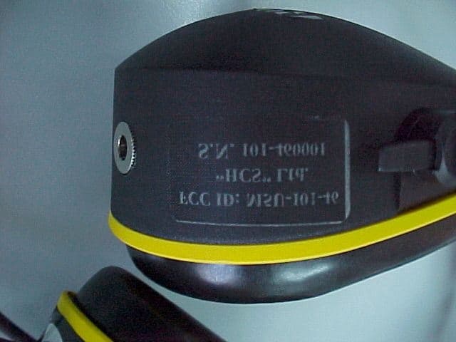
The identification label (material – polyester) is affixed to the lateral side of PAWN101-460C. The drawing is shown below. SERIAL NO This device complies with part 15 of the FCC rules, operation is subject to the following two conditions, 1) This device may not cause harmful Interference, and 2) This device must accept any interference received. Including interference that may cause undesired operation. 1100001 HEAD CONNECTION FCC ID: M5U –101-460C FCC ID: M5U -101-460C N°°: 1100001
Internal Photos
FCC ID:M5U-101-460C Date: March, 2000 Project number:13038 Page 1 of 6 Photograph No.1 PAWN-101-460C transceiver internal view FCC ID:M5U-101-460C Date: March, 2000 Project number:13038 Page 2 of 6 Photograph No.3 PAWN-101-460C transceiver internal view FCC ID:M5U-101-460C Date: March, 2000 Project number:13038 Page 3 of 6 Photograph No.3 PAWN-101-460C transceiver internal view
Internal Photos
FCC ID:M5U-101-460C Date: March, 2000 Project number:13038 Page 4 of 6 Photograph No.4 PAWN-101-460C transceiver internal view FCC ID:M5U-101-460C Date: March, 2000 Project number:13038 Page 5 of 6 Photograph No.5 PAWN-101-460C transceiver PCB view FCC ID:M5U-101-460C Date: March, 2000 Project number:13038 Page 6 of 6 Photograph No.6 PAWN-101-460C transceiver PCB back side view
Operational Description
Private Address Wireless Network Two Way Communications for Extreme Noise Environment MODEL 460C OPERATING MANUAL Thank you for buying this HCS transceiver. This instruction manual contains important safety and operating instruction. Please read it carefully before using the Headset. HEAD CONNECTION SYSTEMS LTd. 112 Soundview Drive, Port Washington NY, 11050 – 1750 Fax: (516) 944-7556 For Extreme Noise Environment HCS Head Connection Systems Ltd . 2 1. Model-460C was tested and approved according the FCC part 90 for Programmable UHF commercial licence - FCC ID: M5U-101-460C GENERAL DESCRIPTION Two-way Programmable radio headsets (earmuffs), up to 4 frequencies, UHF (450-470MHz) transceiver, Ni-HM rechargeable battery operated, built into a highly efficient hearing protection for secure voice communications in noisy environments. Built in connector for Sell- phone / music plug or frequencies program cable. FUNCTIONALITY Enables wireless communication between all headsets and with an optional base-station on common frequencies. The noise-suppressing microphone efficiently reduces background noise. The headset microphone and speakers are used simultaneously with a connected cellular phone. Transmission can be initiated by manually push-to-talk or hands free VOX system. APPLICATIONS The applications for PAWN are many; Shop floors, Power plants, Forestry, Construction sites, Quarries, Recreational areas and other noisy areas where secure communication over short distances are essential. The plug-in sell-phone enables clear communication with the outside world. OPERATING INSTRUCTIONS Simplified controls make PAWN Headsets easy to use. A four-position switch selects the operating mode, either VOX /PTT or PTT. Rotary switch controls On/Off/Volume. 2. PRODUCT LAYOUT 1. PTT - ”talk” button for manual transmission 2. Program /cell phone Plug-in. 3. 4-way switch-VOX/PTT setting with three alternatives for adjusting VOX circuit’s sensitivity, to ensure "Hands-Free" correct microphone activation in relation to external noise levels. The PTT position, is activated via the ”talk” button. 4. Volume On/Off control for adjusting the volume level in the headset. 5. Frequency setting, - Two -position pre-set channels. 6. Charging socket. 1 3 2 5 4 6 3 3. Transmitting and receiving: The headset is in receiving mode, when turned ON by the Volume/ On/Off switch. To transmit voice, make sure that the microphone is very close to your mouth (about ½ “) and the white dot on the microphone is against your mouth. Push the PTT button or adjust the VOX sensitivity and start talking. After releasing the PTT or when you stop talking in VOX mode, you and all other recipients will hear a beep tone- to confirm end of transmission. 4. Adjustment of the VOX sensitivity: A. Maximum sensitivity (first VOX level - opposite to the PTT position) is appropriate for communication in low noise levels - up to 92dB(A). B. Medium sensitivity starts the VOX with this position. Suitable for most noisy area up to 105dB(A). C. Minimum sensitivity (lowest sensitivity- position close to the PTT position) is appropriate for transmissions in high noise levels (up to 130dB and requires an increased voice signal in order to activate the transmitter. Note: When transmitting, you should hear your own voice through the speakers. 5. Suggestions for proper operation: A. It is recommended to use the PTT to transmit if you have a free hand.. B. When using VOX mode, speak continuously and avoid silent periods between words. C. When you receive a transmission, the PAWN blocks VOX transmission, PTT is always available. 6. Should the transmitter not work properly in VOX mode check the following: A. Is the VOX sensitivity position is right for the noise surrounding you? B. Is the microphone positioned close enough to your mouth? C. Are you speaking loudly enough? D. Is the other user transmitting, or is the VOX sensitivity set so high that the transmitter is constantly activated? 7. CTCSS tone (PL Decoder/Encoder) considerations: A. The default internal dip switch position (see page 6) is OFF. B. If you experience interference on the selected channel, it is recommended to change the channel. If you must stay on the first channel, you move the CTCSS dip switch to ON. C. Please note: D. If you are using the VOX system with PL, expect a longer delay between beginning of speech and transmission than by using PTT. The recessives will have a delay of 1-2 seconds. There for you must extend the first word like - DDDDDDave, listen..... E. Every body must change to CTCSS ON in order for this feature to work because it affects all channels. 4 8. BATTERY MAINTENANCE AND CHARGING PROCEDURE Important: Before first use charge the battery for 15 hours. Always charge with power turned off. To save battery power, the unit is programmed to self shut-off within 60 min. if no activity, receiving or transmitting is detected. A chirp tone will be heard 30 second before shutdown. When the battery is almost empty, A number of alert short tone beep will be heard before shutdown, and the red LED light will blink. Important: For best functionality, remove hair around the ears from under the cushions to improve the acoustical seal against the head. Eyeglass temples should be as thin as possible and conform close to the head. Turn on the headset and adjust the volume for best listening level. 10. HEADSET MAINTENANCE AND USER INFORMATION In order to fully benefit from the superior noise attenuation, wear PAWN 100% of the time you are exposed to noise! Regularly clean the outside of PAWN using warm water and a mild detergent. WARNING: The unit must not be submerged in water. Do not store or place PAWN in temperatures exceeding +55 C (13O F). Do not place the unit behind a car windshield or in direct sunlight. Certain chemicals may negatively effect this product. The manufacturer can provide further information. PAWN and especially the cushions may degrade over time and should be examined r…
Text truncated - open the document above for the full version.
Operational Description
"HEAD CONNECTION” COMPANY LTD. MOSHAV BEN-SHEMEN 11 ISRAEL 73115 TEL: 972-8-9211918 FAX: 972-8-9247547 “HEAD CONNECTION” SYSTEMS LTD. PAWN-101 460C - Antenna description Helical Antenna Frequency coverage 430-470 MHz Omni-Directional Sizes - 95 mm in length 6 mm in diameter
Parts List/Tune Up Info
CPU Unit/Mechanical Parts Ref. No.Parts No.DescriptionParts NameVer.Ref. No.Parts No.DescriptionParts NameVer. R360RK3026Chip R.ERJ3GSYJ101VMechanical Parts R361RK3046Chip R.ERJ3GSYJ472VDG0020LCD light DJP82 R362RK3028Chip R.ERJ3QSYJ151VFG0064Mic holder R363RK3058Chip R.ERJ3GSYJ473V R364RK3058Chip R.ERJ3GSYJ473VFK0002Mic spacer R365RK3030Chip R.ERJ3GSYJ221VST0041LCD holder DJP82 R366RK3058Chip R.ERJ3GSYJ473VTL0013Reflection sheet DJP82 R367RK3035Chip R.ERJ3GSYJ561VTN0001Mic shield DJP82 R368RK3050Chip R.ERJ3GSYJ103VAP000502+3.5PeN 1 R369RK3050Chip R.ERJ3GSYJ103VPG0229Mic cushion R370RK3062Chip R.ERJ3GSYJ104VAF000502+3.5FeN 1 R371RK3062Chip R.ERJ3GSYJ104VAN00076Nut M4'0.7 FeN3 R373RK3042Chip R.ERJ3GSYJ222V AN0012Dial nut R377RK3050Chip R.ERJ3GSYJ103VAX0004OP2+8FeB/C3 R378RK3050Chip R.ERJ3GSYJ103V R379RK3050Chip R.ERJ3GSYJ103V DP0113LCD Panel R380RK3001Chip R.ERJ3GSYOROOV RA301RA0021Chip R.EXBV4V103JVEA0050AAntenna RA302RA0011Chip R.EXBV8V103JVES0012ASU-36W0824A RA303RA0022Chip R.EXBV4V472JVFG0077Battery cushion RA304RA0010Chip R.EXBV8V472JV FG0107Mic sheet DJP7 RT301RH0146Trim. Pot.MVR22HXBRN473FG0108Battery rubber DJP7 RT302RH0154Trim. Pot.MVR22HXBRN105FG0132Battery rubber L FG0161On air light SW307UU0018SwitchSOP-112HST sw306UU0018SwitchSOP-112HST SW309UU0018SwitchSOP-112HST VR301RV0025V.R.TP96NOON FM0066Pin X301XQ0072Crystal38CHT 4.0000MHZFP0104Lock lever KP0032Battery cover W301MKCLH2AAWire SD0027ABattery terminal B SD0028Battery terminal C SD0041Plus spring SD0042Minus spring SD0043ACharge spring SD0044Charge terminal ST0075ZSP holder TG0021SPnet TW0007AJack cap TW0008Cover rubber DJP82 TW0009Battery rubber DJP82 TZ0059Insulator DJP82
Schematics
CTCSS TONE ENCODER/DECODER SCHEMATICS ANALOG-PAWN400REV2-DECODERrev2 Decoder A 22Monday, March 15, 1999 Title SizeDocument NumberRev Date:Sheet of C3C C3C C3C was 270K was 5.6K was 470K was 1.5M was 12K DGND V+ V+ C64 15pF C63 1uF C70 1uF U10 AK2341 123456789 101112 242322212019181716151413 R64 200K R62 100K U9B LMC662 + - 5 6 7 8 4 R68 100k C71 1uF C69 4700pF C73 0.1uF C60 1000pF R69 100 R67 100k R71 10K R70 10K C74 10uF C65 10uF C72 10uF C66 0.1uF C67 22pF C68 22pF R65 100 Y1 3.6864MHz R61 10K R66 1M R63 15K R59 22K R60 160K C61 10uF C62 10uF C56 1uF C59 1000pF R58 1K R53 5.1k C55 100pF R54 300k C58 10uF C54 10uF R55 15K C57 10uF R57 1M R56 15K U9A LMC662 + - 3 2 1 8 4 VR2 TS53YL-50K-20% 1 3 2 RX_IN VCC TSQD DGND RX_BPF_OUT T-CLK T-DATA T-STRB TONE DCS_DET GND ASSEMBLY SCHEMATICS OUTSIDE430.DSN0 PAWN460- EXTERNAL WIRING A 11Sunday, March 28, 1999 HEAD CONNECTION SYSTEMS LTD. Title SizeDocument NumberRev Date:Sheet of CHANNEL SELECT VOX SELECT PAWN400 REV 0 CARD LEFT CUP RIGHT CUP BROWN RED VIOLET BLACK DARK RED PINK DARK BROWN YELLOW GREEN WHITE PURPLE GRAY WHITE BLUE YELOW GRAY PINK WHITE GREEN YELLOW DARK BROWN PINK DARK RED BROWN BRIDGE SOLDER x10 CABLE SHILDED 6 WIRE LiYD11Y 0033 206 R+T SHIELD VIOLETBLACK Shield VOX1 VOX2 VOX3 VOX_SENSE SP16 +BAT GREEN GREEN GREEN 9 SP12 CH_B SP10 RED RED PURPLE 11 BLUE BLUE BLUE 14 BLACK BROWN BROWN 1 BLACK BLACK GRAY 12 BROWNSP14 SPKR+ SPKR- SP15 4 MIC 3 MICG LED RED RED 2 CH_A SP9 WHITE WHITE WHITE 10 WHITE 13 WHITE PTT SP4 SP3SP7 SP8 SP5 SP11 SP6 SP13 SP17 D3 3MM RED LED D3 BAT-65 ANT1 ALINCO/ EA0050A SW4 C&K MB04-L1NZQ A 1 2 3 4 6 7 8 9 B SW3 C&K/ MB04-L1NZQ A 1 2 3 4 6 7 8 9 B J3 ORBITEC/ OR775550 + - MIC1 ELECOM/ MFD-68 + - LS2 ELECOM/4025FK6E + - R102 20/ 0.2Watt BT1 PANASONIC/ Ni-MH 3.6V/1300mAh J3 MOLEX/ 51021-1400 1 2 3 4 5 6 7 8 9 10 11 12 13 14 SW2 APEM-18535CD 1 3 2 21 21 21 21 21 2121 RF UNIT SCHEMATICS-
Test Report
Test Report: HEADEMC_FCC.13823.doc Date: March, 2000 Page 28 of 62 HERMON LABORATORIES Photograph 4.3.1 Set up for ERP measurement, substitution method Test Report: HEADEMC_FCC.13823.doc Date: March, 2000 Page 29 of 62 HERMON LABORATORIES 4.4 Occupied bandwidth measurements according to FCC part 90 paragraph 209 4.4.1 General According to paragraph 90.209 (5) the maximum authorized bandwidth shall be 11.25 kHz in 450 – 470 MHz frequency band. 4.4.2 Test procedure The EUT was set up as shown in Photograph 4.4.1. The measurements were performed using spectrum analyzer. The occupied bandwidth was measured as a frequency band between points where power envelope of carrier, modulated with normal signal, drops 23 dB below unmodulated carrier. The test results for 3 channels are shown in Plots 4.4.1 to 4.4.3. Reference numbers of test equipment used HL 0465 HL 0521 HL 0604 Full description is in Appendix A. Test Report: HEADEMC_FCC.13823.doc Date: March, 2000 Page 30 of 62 HERMON LABORATORIES Plot 4.4.1 Occupied bandwidth measurements test result F = 451.0175 MHz Occupied bandwidth = 6.25 kHz Test Report: HEADEMC_FCC.13823.doc Date: March, 2000 Page 31 of 62 HERMON LABORATORIES Plot 4.4.1 Occupied bandwidth measurements test result F = 460.65 MHz Occupied bandwidth = 7.38 kHz Test Report: HEADEMC_FCC.13823.doc Date: March, 2000 Page 32 of 62 HERMON LABORATORIES Plot 4.4.1 Occupied bandwidth measurements test result F = 469.98 MHz Occupied bandwidth = 6.75 kHz Test Report: HEADEMC_FCC.13823.doc Date: March, 2000 Page 33 of 62 HERMON LABORATORIES Photograph 4.4.1 Occupied bandwidth test setup
Test Report
Test Report: HEADEMC_FCC.13823.doc Date: March, 2000 Page 21 of 62 HERMON LABORATORIES Plot 4.1.2 Radiated emission measurements test results, electric field, frequency range 30 MHz - 1 GHz Stand-by mode, horizontal polarization Test Report: HEADEMC_FCC.13823.doc Date: March, 2000 Page 22 of 62 HERMON LABORATORIES Plot 4.1.3 Radiated emission measurements test results, electric field, frequency range 1 GHz – 2 GHz Stand-by mode, vertical and horizontal polarization Test Report: HEADEMC_FCC.13823.doc Date: March, 2000 Page 23 of 62 HERMON LABORATORIES Figure 4.2.1 Radiated emissions test setup for table-top equipment Anechoic chamber Ground plane Plastic antenna mast Raised measuring antenna EUT 3 m 1m 4 m Wooden table 1.5 (L) x 1 (W) x 0.8 (H) m Metal turntable flush mounted. Diameter=2 m Test Report: HEADEMC_FCC.13823.doc Date: March, 2000 Page 24 of 62 HERMON LABORATORIES Photograph 4.2.1 Setup for radiated emission measurements 1 – 2 GHz Test Report: HEADEMC_FCC.13823.doc Date: March, 2000 Page 25 of 62 HERMON LABORATORIES Photograph 4.2.2 Setup for radiated emission measurements Test Report: HEADEMC_FCC.13823.doc Date: March, 2000 Page 26 of 62 HERMON LABORATORIES 4.3 Effective radiated power measurements according to FCC part 90 paragraph 267 (a3) 4.3.1 General This test was performed to determine maximal effective radiated power. The standard specification limit is 2 W ERP = 33 dBm. 4.3.2 Test procedure The EUT was tested according to the substitution method with dipole antenna. The test was performed at HL open field test site at 3-meter test distance, i.e. the distance between measuring antenna and EUT boundary. The EUT was placed on wooden table, as shown in Photograph 4.3.1. Electric field power values were recorded. Then the EUT was replaced with dipole antenna connected to signal generator. The generator output was adjusted to obtain an electric field power level equal to that of the EUT. Maximum ERP was calculated from equation: ERP max = P out gen – Cable loss + Antenna gain Test results are recorded in Table 4.3.1. Reference numbers of test equipment used HL 0465 HL 0521 HL 0589 HL 0604 HL 0614 HL 0661 HL 1175 Full description is in Appendix A. Test Report: HEADEMC_FCC.13823.doc Date: March, 2000 Page 27 of 62 HERMON LABORATORIES Table 4.3.1 ERP measurement Frequency, MHz E, dBμμV/m P gen , dBm Cable loss, dB Antenna gain, dB ERP max , dBm Limit, dBm Pass/ Fail 451.017 115.12 17 0.5 0.56 17.06 33 Pass 460.65 117.95 20 0.5 0.56 20.06 33 Pass 469.98 118.07 20 0.5 0.56 20.06 33 Pass
Test Report
Test Report: HEADEMC_FCC.13823.doc Date: March, 2000 Page 34 of 62 HERMON LABORATORIES 4.5 Emission mask according to FCC part 90 paragraph 210 4.5.1 General Any emission must be attenuated below the power (P) of the highest emission contained within the authorized bandwidth as follows: (1) On any frequency from the center of the authorized bandwidth f 0 to 5.625 kHz removed from f 0 : Zero dB. (2) On any frequency removed from the center of the authorized bandwidth by a displacement frequency (f d in kHz) of more than 5.625 kHz but no more than 12.5 kHz: At least 7.27(f d – 2.88 kHz) dB. (3) On any frequency removed from the center of the authorized bandwidth by a displacement frequency (f d in kHz) of more than 12.5 kHz: At least 50 + 10 log(P) dB or 70 dB, whichever is the lesser attenuation. 4.5.2 Test procedure For test setup refer to Photographs 4.2.1, 4.2.2, 4.5.1. The emission mask, calculated according to formulas (1) – (3) is shown in Figures 4.5.1, 4.5.2. Spurious emissions outside the specified bandwidth (f 0 – 12.5 kHz, f 0 + 12.5 kHz) were compared with the limit, expressed as follows: Att min = 50 + 10 log(P), where for transmission frequency F = 451.017 MHz P = 17.06 dBm = 0.05 W, and Att min = 50 + 10log 0.05 = 50 – 13 = 37 dB, refer to Figure 4.5.1, for transmission frequency F = 460.65 MHz and 469.98 MHz P = 20.06 dBm = 0.1 W, and Att min = 50 + 10log 0.1 = 50 – 10 = 40 dB, refer to Figure 4.5.2. No spurious emissions were found in frequency range 9 kHz to 30 MHz. Test results are shown in Plots 4.4.2 to 4.4.18. Reference numbers of test equipment used HL 0029 HL 0041 HL 0411 HL 0465 HL 0521 HL 0557 HL 0589 HL 0604 HL 0661 HL 1116 HL 1175 Full description is in Appendix A. Test Report: HEADEMC_FCC.13823.doc Date: March, 2000 Page 35 of 62 HERMON LABORATORIES Figure 4.5.1 Emission mask (F 0 = 451.017) Fo Fo + 5.625 kHz - 19.95 - 69.94 0 Attenuation versus carrier - 37 Fo + 12.5 kHz Fo - 5.625 kHz Fo - 12.5 kHz Figure 4.5.2 Emission mask (F 0 = 460.65, F 0 = 469.98) Fo Fo + 5.625 kHz - 19.95 - 69.94 0 Attenuation versus carrier - 40 Fo + 12.5 kHz Fo - 5.625 kHz F o - 12.5 kHz Test Report: HEADEMC_FCC.13823.doc Date: March, 2000 Page 36 of 62 HERMON LABORATORIES Table 4.5.1 Spurious emissions test results Frequency, MHz Peak Ampl, dBm P gen, dBm Cable loss, dB Gain ant, dB P out., dBm Limit, dBm Pass / Fail 902.032184 69.56 -28 0.7 1.84 -26.9 -20 Pass 921.294175 68.73 -28 0.7 1.84 -26.9 -20 Pass 939.959875 68.73 -28 0.7 1.84 -26.9 -20 Pass 1353.033452 72.34 -30 0.8 7.0 -23.8 -20 Pass 1381.945000 71.81 -30 0.8 7.0 -23.8 -20 Pass 1409.945000 60.97 -41 0.8 7.0 -34.8 -20 Pass 1804.183682 58.83 -34 0.9 6.8 -28.1 -20 Pass 1842.542500 61.97 -40 0.9 6.8 -34.1 -20 Pass 1879.968750 67.04 -35 0.9 6.8 -29.1 -20 Pass 2255.167176 59.61 -42 1.0 6.9 -36 -20 Pass 2303.358750 61.87 -40 1.0 6.9 34.1 -20 Pass 2349.697500 61.69 -40 1.0 6.9 -34.1 -20 Pass 2764.020000 58.50 -43 2.1 7.5 -37.6 -20 Pass Test Report: HEADEMC_FCC.13823.doc Date: March, 2000 Page 37 of 62 HERMON LABORATORIES Plot 4.5.1 Reference level, F 0 = 451.017 Test Report: HEADEMC_FCC.13823.doc Date: March, 2000 Page 38 of 62 HERMON LABORATORIES Plot 4.5.2 Emission mask, F 0 = 451.017 Test Report: HEADEMC_FCC.13823.doc Date: March, 2000 Page 39 of 62 HERMON LABORATORIES Plot 4.5.3 Emission mask, F 0 = 451.017 Test Report: HEADEMC_FCC.13823.doc Date: March, 2000 Page 40 of 62 HERMON LABORATORIES Plot 4.5.4 Spurious emissions, F 0 = 451.017 Signal Frequency, MHz Peak Ampl, dBm P gen, dBm Cable loss, dB Gain ant, dB P out., dBm 1 451.016046 115.12 17 05 0.56 17.06 2 902.032184 69.56 -28 0.7 1.84 -26.9
Test Report
Test Report: HEADEMC_FCC.13823.doc Date: March, 2000 Page 41 of 62 HERMON LABORATORIES Plot 4.5.5 Spurious emissions, F 0 = 451.017 Signal Frequency, MHz Peak Ampl, dBm P gen, dBm Cable loss, dB Gain ant, dB P out, dBm 1 1353.033452 72.34 -30 0.8 7.0 -23.8 2 1804.183682 58.83 -34 0.9 6.8 -28.1 3 2255.167176 59.61 -42 1.0 6.9 -36 Test Report: HEADEMC_FCC.13823.doc Date: March, 2000 Page 42 of 62 HERMON LABORATORIES Plot 4.5.6 Spurious emissions, F 0 = 451.017 Test Report: HEADEMC_FCC.13823.doc Date: March, 2000 Page 43 of 62 HERMON LABORATORIES Plot 4.5.7 Reference level, F 0 = 460.65 Test Report: HEADEMC_FCC.13823.doc Date: March, 2000 Page 44 of 62 HERMON LABORATORIES Plot 4.5.8 Emission mask, F 0 = 460.65
Test Report
Test Report: HEADEMC_FCC.13823.doc Date: March, 2000 Page 53 of 62 HERMON LABORATORIES Plot 4.5.17 Spurious emissions, F 0 = 469.98 Test Report: HEADEMC_FCC.13823.doc Date: March, 2000 Page 54 of 62 HERMON LABORATORIES Photograph 4.5.1 Harmonics emissions measurements, substitution method, frequency range 1GHz – 5 GHz Test Report: HEADEMC_FCC.13823.doc Date: March, 2000 Page 55 of 62 HERMON LABORATORIES 4.6 Frequency stability measurements according to FCC part 90 paragraph 213 4.6.1 General According to paragraph 90.213, the minimum frequency stability limit (in parts per million) is 2.5 ppm for mobile equipment designed to operate with a 12.5 kHz channel bandwidth in frequency range 421 – 512 MHz. For frequency 451017.5 Hz the specified limit is 1128 Hz. For frequency 460648.7 Hz the specified limit is 1152 Hz For frequency 469979.6 Hz the specified limit is 1175 Hz 4.6.2 Test procedure The EUT was set up as shown in Photographs 4.6.1, 4.6.2. The frequency stability was investigated for various temperatures in the range from –30°C to +50°C. Test results are recorded in Table 4.6.1. The EUT was found to comply with requirements of paragraph 90.213. Reference numbers of test equipment used HL 0026 HL 0493 Full description is in Appendix A. Test Report: HEADEMC_FCC.13823.doc Date: March, 2000 Page 56 of 62 HERMON LABORATORIES Table 4.6.1 Frequency stability test results Temperature, °°C Displacement for F = 451.0175, kHz Displacement for F = 460.6487, kHz Displacement for F = 469.9796, kHz -30 + 0.6 + 0.6 + 1.02 -20 + 0.5 + 0.7 + 0.9 -10 + 0.5 + 0.7 + 0.93 0 + 0.3 + 0.7 + 1.07 10 - 0.3 + 0.2 + 0.4 20 - 0.4 - 0.3 - 0.1 22, Vmax reference reference reference 22, Vmin + 0.7 + 0.8 + 1.1 30 - 0.7 - 0.7 - 0.4 40 - 0.2 - 0.3 + 0.3 50 + 0.7 + 0.5 + 0.6 Test Report: HEADEMC_FCC.13823.doc Date: March, 2000 Page 57 of 62 HERMON LABORATORIES Photograph 4.6.1 Frequency stability test setup Test Report: HEADEMC_FCC.13823.doc Date: March, 2000 Page 58 of 62 HERMON LABORATORIE…
Text truncated - open the document above for the full version.
Contact Information
Applicant
Yoram Peled(General Manager)
Technical Contact
Hermon LaboratoriesEdward Usoskin
[email protected]+972 66288001
HaRakevet Industrial Zone · Binyamina · Israel
Non-Technical Contact
Head Connection Systems Ltd.Yoram Peled
[email protected]972 8 9211918
Test Firm
Hermon Laboratories Ltd.Alexander Usoskin
Technical Specifications
| # | Rule Parts | Frequency Range | Power Output | Emission | Tolerance |
|---|---|---|---|---|---|
| 1 | 90 | 450 MHz - 470 MHz | 101.00 mW | F3E | 0.0000025000 |
Other Applications from Head Connection Systems Ltd
M5U-101-460
Jun 21, 1999FRS transceiver PAWN 101-460
Equipment Class
FRT - Part 95 Family Radio Body Worn Transmitter