M5X-ACT8HTransmitter
Mipro Electronics Co Ltd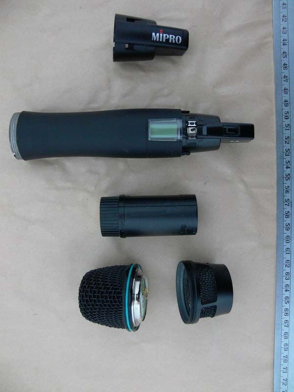
Click to zoom
Application Details
- Equipment Class
- TBF - Licensed Broadcast Transmitter Held to Face
- Date of Grant
- Feb 01, 2007
- Application Purpose
- Original Equipment
- Date of Application
- Feb 01, 2007
- Equipment Note
- Transmitter
- Frequency Range
- 614.00000000 - 806.00000000
- Company
- Mipro Electronics Co Ltd
- Country
- Taiwan
Documents & Files
Document Text
Text extracted from the exhibit documents filed with the FCC. Open a document above to read the original.
Users Manual
Instruction Manual ACT-8H : DIGITAL WIRELESS HANDHELD MICROPHONE ACT- 8T : DIGITAL WIRELESS BODY PACK TRANSMITTER Disposal Dispose the unusable device according to valid regulations. Disposal of spent batteries/accumulators You are required by law to return all spent batteries. Disposing of used batteries with domestic waste is prohibited! Batteries / NiCad cells containing toxins are marked by accompanying symbols that refer to the prohibition of disposal with domestic waste. The designations for the decisive heavy metals are: Cd=cadmium, Hg=mercury, Pb=lead. You may return spent batteries/accumulators free of charge to the recycling centres, our outlets or anywhere else where batteries/accumulators are sold. By doing so, you fulfil the legal requirements and contribute to the conservation of our environment! 2005-08-13 Electronics Co., Ltd. Head office: 814, Pei-Kang Road, Chiayi, 60096, Taiwan. Taipei office: 5, Lane 118, Sung-teh Road, 10075, Taipei, Taiwan. Web-http: //www.mipro.com.tw E-mail: [email protected] 2CE263 Digital Wireless Microphone Systems Digital Wireless Microphone Systems 1.Upper Grille: Provides access & protection to capsule. 2.Capsule Module: Metal grille integrated to protect the capsule. 3.Housing: Houses various PCB and Li-Poly battery module. 4.LCD Display Panel: Displays group, frequency, gain, battery level, input SPL and error code. 5.Lithium-Polymer Battery Back: Built-in and detachable Li-Poly battery module can be recharged alone or together with transmitter; gives 8 hours continuous operation time. 6.Power Switch: Switch to ''ON'' when using microphone and ''OFF'' position when not. 7.MODE: Mode selection button. 8.SET: Parameter selection button. 9.Color Rear Cap: Designed to protect the ON/OFF switch to help prevent the user turning off the microphone during use. 10.ACT Receptor: Signal reception via the ACT function; automatically programs the frequency and the encryption code from the receiver. 11.Battery Charging Contact: For charging battery module. 1.The world's first 24-bit true digital handheld wireless microphone, combining the best design and the most advanced features. 2.Magnesium alloy housing offers a comfortable feel, balanced weight allocation and special surface finishing, giving it a truly professional appearance and quality. 3.Available in three colors: black, rose metallic and blue diamond. Custom- made colors are also available for special requirements. 4.Anti-roll & anti-pop microphone capsule module with extremely low touch noise characteristics. 5.Optional interchangeable microphone capsule modules. 6.Bright LCD display shows working channel, battery status, input level and error codes. 7.Integrated antenna provides maximum transmission efficiency and the patented color rear caps protect the on/off as well as the audio sensitivity switches while providing easy channel identification. 8.Built-in and detachable lithium-polymer (Li-Poly) battery pack can be recharged alone or together with the transmitter. Eight continuous hours of operation are possible due to its compact size and high-efficiency circuitry design. 9.Second generation of the world's first ACT function rapidly and precisely sets up the transmitter frequency. 1. Part Names and Functions 1 2 () 1234 5 7 MODE O F F SET 869 Main features: 1110 DIGITAL WIRELESS HANDHELD MICROPHONE DIGITAL WIRELESS HANDHELD MICROPHONE ACT-8H DIGITAL WIRELESS HANDHELD MICROPHONE Fully Lit VFD Display 4. LCD Panel Functions () 2. Battery Removals and Installation Open the upper grille and capsule module, then turning the battery pack in a counterclockwise direction in order to replace the battery (see diagram 2). To reinstall the battery module after loading the new battery, turn it in a clockwise direction (see diagram 2). **NOTE: When microphone is not in use, please turn the power off. Battery pack can be recharged while in the transmitter or remove from transmitter and charged alone. 3 4 3. Rear Cap On/Off Switch Protection The patented color rear cap serves two purposes, provides easy channel identification and protecting the toggle on/off switch. It allows the on/off switch to either be exposed or concealed as desired. You can avoid unintended switching off of the microphone by rotating the color rear cap 180 degrees to cover the on/off switch completely. **Note: When using the microphone, the color rear cap must be in place. A RF AF B BT Mode Switch: To select from different menu Function Selection: The LCD panel has 6 functions displayed sequentially; their respective descriptions and operations are as follows: a.Press MODE (7) to access the 6 different functions. Once a function is selected, it starts flashing on the screen. If parameter needs to be modified on selected function, press SET (8) to modify the value while the display is still flashing. Once done, leave it for 5 seconds until it stops flashing and the selection will be programmed into the transmitter. A. Operation Guide FREQLOW--CU AF--SEN LIMITENCRYPGR--CH OPENLOCK 180 DIGITAL WIRELESS HANDHELD MICROPHONE DIGITAL WIRELESS HANDHELD MICROPHONE **NOTE: When program a special frequency via monitoring software; LCD screen cannot display the number. This is because this special channel is not in the preset group and channel. Therefore, LCD panel will look like illustration below. **NOTE: To modify transmitter's group, channel and frequency, all three must be set at the receiver and transmit the new setting to transmitter via ACT. 5 6 (1)GR-CH: Displays Information of Group and Channel RF RF AF AF BT BT RF RF AF AF BT BT 5 B. Operation Guide: B. Operation Guide: a.Press ''MODE'' and stop on "GR-CH" function, the display showing current group and channel will be flashing. After 5 seconds, the display will stop flashing. b."GR-CH" function is added to display group and channel information. Changing current group and channel must be done on the receiver. GR--CH MODE 5 a.Press ''MODE'' and stop on "FREQ" function, the display s…
Text truncated - open the document above for the full version.
Users Manual
7 8 (5) LIMIT: Setup and Change of Input Limit (6) ENCRYP: Displays Information of Encryption SETOFF SETON RFRF AFAF BTBT RF AF BT 5 B. Operation Guide: a.Press "MODE" and stop on "LIMIT" function, the display showing current state will be flashing and is ready to be modified. b.Press ''SET'' to change the setting to "ON" or "OFF". A. Operate via MODE Button LIMIT MODE ON OFF SET (4) AF-SEN: Setup and Change of Input Sensitivity SET6dB RFRF AFAF BTBT RF AF BT 5 AF--SEN MODE 0 DB SET 6 DB SET 12 DB SET 0 dB6 DB12 DB B. Operation Guide: A. Operate via MODE Button ENCRYP MODE ON OFF a.Press "MODE" and stop on "ENCRYP" function, the display showing current state will be flashing. A. Operate via MODE Button B. Operation Guide: a.Press "MODE" and stop on "AF-SEN" function, the display showing current state will be flashing and is ready to be modified. b.Every push of ''SET'' button, the dB value increases by 6dB to a maximum of 12dB. **NOTE: 1. The higher the gains are set, the lower the dynamic range for signal input. Meanwhile the danger of unwanted noises and feedback getting into the system would obviously rise. 2. It is advisable to generally set the sensitivity to a level between 0dB-6dB. 3. When set at 0 dB, the maximum SPL for handheld microphone is 145dB. **NOTE: When the LIMIT is ''ON'', the maximum output of the receiver is limited to 1V. **NOTE: "ENCRYP" function is added to display status information only. Changing of current status must be done from receiver via ACT. DIGITAL WIRELESS HANDHELD MICROPHONE DIGITAL WIRELESS HANDHELD MICROPHONE 5. Cautions 1.Unless necessary, do not remove the battery module from the microphone when the microphone needs to be charged. The best way is to put the whole microphone into the charger for recharging; this prolongs life of contact spring on the capsule module. 2.Traditionally designed microphones have an antenna protruding on the bottom of the housing. Modern designs have a built-in antenna in the upper or lower housing. Antenna section of ACT-8H is located on the end of the transmitter (where the color cap is). Users should avoid holding the microphone over or near antenna section as this will deteriorate transmission efficiency, and deterioration gets even more severe if users hold the microphone directly above the antenna with both hands.. 3.Many performers tend to hold the microphone by the grille. Unfortunately, this position seriously degrades both the sound quality and directionality of a microphone. Even the most expensive microphone will have its original sound quality compromised by this method. Grabbing a microphone by the grille will isolate the capsule's acoustic resonance circuit and or change the capsule resonator's frequency. This results in an inferior performance in both frequency response and the separation of directionality. In addition, a palm's sound-focusing effect will tend to strengthen resonances in certain frequencies and can cause unwanted echo. 4.A proper technique is required for using directional microphones because the distance between the microphone and your mouth has a significant impact on sensitivity and performance. There is an inverse relationship between microphone sensitivity and the distance from the mouth to the microphone. Consequently, performers with a ''weaker'' sound level cannot expect to hold the microphone too far away from their mouth and compensate by turning up the amplifier volume to increase the sound level as this can easily cause echo or feedback. In contrast, performers with a ''louder'' sound level should not hold the microphone too close as this can easily result in distortion by causing the amplifier system to be overloaded. Furthermore, a large-diaphragm directional microphone has a very distinct proximity effect. When the microphone is close to the mouth, the bass response is strengthened as the distance gets closer. Therefore, if a performer's sound is insufficient in bass, they can hold the microphone closer and use the proximity effect to help compensate for the lower bass level. Conversely, if a performer's voice is too heavy in the bass register, increasing the distance between the microphone and their mouth will decrease the proximity effect and reduce the bass response, thus making their voice become clearer and brighter. 5.It is recommended to keep the grille and sponge windscreen clean to avoid any substance blocking the proximity effect of the microphone. 9 10 BTBTBTBTBT 7. BT: Displays Information of Battery Level 90%80%40%10%0% 8. ERR: Error Code ROM-ERTransmitter does not have the initial data so the microphone is completely dead. ERROR1Failure on RF circuitry, frequency can not be programmed. NO----O3Frequency to be programmed into the transmitter exceeds its highest frequency of designated frequency band of the transmitter. NO----O4Frequency to be programmed into the transmitter exceeds its lowest frequency of designated frequency band of the transmitter. BT 100% (9) PO-OFF: System Turning Off When the power is turned off, the LCD displays ''PO-OFF'' indicating the system is at the state of shutting down and then automatically cuts the power off. The display panel has no further message afterward. DIGITAL WIRELESS HANDHELD MICROPHONE DIGITAL WIRELESS HANDHELD MICROPHONE When the battery level drops down to 10%, please replace or recharge the battery. If the battery continues to be used at a very lower level, the LCD will display and then automatically switch off to avoid over-discharging the battery. "PO--OFF" If the LCD displays ''ERR'' after turning on the power, it indicates the operation is not correct. The error codes are as follows: **NOTE: NO----OR3 and NO----OR4 will not change transmitter's original frequency, and the transmitter still operates normally with error message on display.. To remove error message from display panel, please switch off the transmitter and switch it on again. 11 12 1.Super-compact magnesium alloy housing protects the circuit board.…
Text truncated - open the document above for the full version.
Users Manual
16 5 15 FREQ MODE SETOFF SETON RFRF AFAF BTBT RF AF BT 5 LOW--CU MODE ON OFF SET **NOTE: When program a special frequency via monitoring software; LCD screen cannot display the number. This is because this special channel is not in the preset group and channel. Therefore, LCD panel will look like illustration below. (1)GR-CH: Displays Information of Group and Channel RF RF AF AF BT BT RF RF AF AF BT BT 5 B. Operation Guide: a.Press ''MODE'' and stop on "GR-CH" function, the display showing current group and channel will be flashing. After 5 seconds, the display will stop flashing. b."GR-CH" function is added to display group and channel information. Changing current group and channel must be done on the receiver. GR--CH MODE RF AF BT RF AF BT 5 "MHz" A. Operate via MODE Button (2) FREQ: Displays Information of Transmitter Frequency A. Operate via MODE Button B. Operation Guide: a.Press ''MODE'' and stop on "FREQ" function, the display showing current frequency will be flashing. After 5 seconds, the display will stop flashing. B."FREQ" function is added to display frequency information. Changing current frequency must be done on the receiver. **NOTE: To modify transmitter's group, channel and frequency, all three must be set at the receiver and transmit the new setting to transmitter via ACT. (3) LOW-CU: Setup and Change of Low Frequency Cut Off B. Operation Guide: A. Operate via MODE Button a.Press ''MODE'' and stop on "LOW-CU" function, the display showing current state will be flashing and is ready to be modified. b.Press ''SET'' button to change to ''ON'' or ''OFF'' as desired. **NOTE: When the LOW-CU function is ''ON'', the frequency response below 100Hz will decrease about 4dB with a slope of -6dB/Octave. DIGITAL WIRELESS BODY PACK TRANSMITTER DIGITAL WIRELESS BODY PACK TRANSMITTER 17 18 SETOFF SETON RFRF AFAF BTBT RF AF BT 5 LIMIT MODE ON OFF SET SET10dB RFRF AFAF BTBT RF AF BT 5 AF--SEN MODE 0 DB SET 10 DB SET 20 DB SET 30 DB SET 0 DB10 DB20 DB30 DB ENCRYP MODE ON OFF DIGITAL WIRELESS BODY PACK TRANSMITTER DIGITAL WIRELESS BODY PACK TRANSMITTER (4) AF-SEN: Setup and Change of Input Sensitivity A. Operate via MODE Button B. Operation Guide: a.Press "MODE" and stop on "AF-SEN" function, the display showing current state will be flashing and is ready to be modified. b.Every push of ''SET'' button, the dB value increases by 10dB to a maximum of 30dB. **NOTE: 1. The higher the gains are set, the lower the dynamic range for signal input. Meanwhile the danger of unwanted noises and feedback getting into the system would obviously rise. 2. It is advisable to set the sensitivity level at 0dB when using electric guitar. 3. When set at 0 dB, the maximum input level without causing distortion to the transmitter is 1 Vrms (0 dBv). Hence, please make sure the input signal does not exceed 1 Vrms. SPL for handheld microphone is 145dB. (5) LIMIT: Setup and Change of Input Limit A. Operate via MODE Button B. Operation Guide: a.Press "MODE" and stop on "LIMIT" function, the display showing current state will be flashing and is ready to be modified. b.Press ''SET'' to change the setting to "ON" or "OFF". **NOTE: When the LIMIT is ''ON'', the maximum output of the receiver is limited to 1V. (6) ENCRYP: Displays Information of Encryption A. Operate via MODE Button B. Operation Guide: a.Press "MODE" and stop on "ENCRYP" function, the display showing current state will be flashing. **NOTE: "ENCRYP" function is added to display status information only. Changing of current status must be done from receiver via ACT. 19 20 4. Cautions 1.Adjust the gain knob to the appropriate level (The gain level needs to be set at 0dB level when using an electric guitar). 2.Plug the microphone connector into the AF input (1) and then secure the connector by turning it in a clockwise direction, as shown in Fig. 4. 3.When the antenna has been removed, the body pack transmitter should remain ''OFF'' to prevention future deterioration of signal transmission. 4.If the transmitter is on without any microphone connected to the AF input socket, the system will clearly have noises of both high and low frequencies. They will do no harm to the system, but will be annoying to the listener, so it would be best to switch off the transmitter when disconnecting the microphone. BTBTBTBTBT 90%80%40%10%0% BT 100% DIGITAL WIRELESS BODY PACK TRANSMITTER DIGITAL WIRELESS BODY PACK TRANSMITTER 7. BT: Displays Information of Battery Level When the battery level drops down to 10%, please replace or recharge the battery. If the battery continues to be used at a very lower level, the LCD will display and then automatically switch off to avoid over-discharging the battery. "PO--OFF" 8. ERR: Error Code ROM-ERTransmitter does not have the initial data so the microphone is completely dead. ERROR1Failure on RF circuitry, frequency can not be programmed. NO----O3Frequency to be programmed into the transmitter exceeds its highest frequency of designated frequency band of the transmitter. NO----O4Frequency to be programmed into the transmitter exceeds its lowest frequency of designated frequency band of the transmitter. (9) PO-OFF: System Turning Off When the power is turned off, the LCD displays ''PO-OFF'' indicating the system is at the state of shutting down and then automatically cuts the power off. The display panel has no further message afterward. If the LCD displays ''ERR'' after turning on the power, it indicates the operation is not correct. The error codes are as follows: **NOTE: NO----OR3 and NO----OR4 will not change transmitter's original frequency, and the transmitter still operates normally with error message on display.. To remove error message from display panel, please switch off the transmitter and switch it on again. Lavalier Headset Capsule Connector The ridge on the connector must match the indentation on the socket when inserting. (Fig.4) 6. High Frequency Bypass a.When other microphones are in use, some changes may be needed to anot…
Text truncated - open the document above for the full version.
Users Manual
3. CAUTIONS: (1) (2) (3) 2. Battery Charger Instructions: 1.Plug the provided DC power transformer into AC outlet and attach the battery charger as shown in diagram (4). 2.Insert the transmitter or battery module into the appropriate charging dock. 1. Part Names and Functions 1. Microphone Charger: Accepts both handheld and body pack transmitters. 2.Microphone Charging Indicator: (a) Red light flashing indicates battery is in the process of charging. (b) Green light flashing indicates battery is fully charged (requires maximum of 4 hours). 3.Charger for Lithium-Polymer Battery: Accepts lithium-polymer battery module from handheld microphone as well as body pack transmitter. 4.Battery Module Charging Indicator: (a) Red light flashing indicates battery is in the process of charging. (B) Green light flashing indicates battery is fully charged (requires maximum of 4 hours). 5. Two chargers can be operated at the same time. This appears to require a cable to connect charger one to charger two using the same DC power supply. Is this correct and is this cable provided? What is the maximum # of chargers that can be connected together in this manner (to the same DC power supply)? 6.DC power supply input. (4) If the voltage to the charger is too high, it will damage the charger, rechargeable battery and microphone at the same time. We recommend a 12V/1A DC power supply. 23 24 (5) (6) MP-8 LITHIUM-POLYMER BATTERY CHARGER MP-8 LITHIUM-POLYMER BATTERY CHARGER 1.The transmitter must be switched off when it is charging. 2.Please do not use any other type of battery charger for safety reasons. 3.Please use only the specific type of transformer designed to work with the MIPRO charger to avoid voltage problems. (Fig.4) (Fig.1) (Fig.3)(Fig.2) FCC ID: M5X-ACT8H THIS DEVICE COMPLIES WITH PART 74 OF TH E FCC RULES AND RSS-123 Issue1 OF CANADA. OPERATION IS SUBJECT TO TH E FOLLOWING TWO CONDITIONS: (1) This device may not cause interference. (2) This device must accept any interference, including in terference that may cause undesi red operation of the device. This equipment complies with FCC RF radiation exposu re limits set forth for an uncontrolled environment. This equipment should be installed and operat ed with a minimum distance of 20 centimet ers between the radiator and your body.
Attestation Statements
MIPRO ELECTRONICS CO., LTD. Head Office: 814, Pei-kang Road, Chiayi, Taiwan. Taipei: 5, Lane 118, Sung-teh Road, Taipei. ISO 9001 Certificate No. 041007829 TEL:05-238-0809 TEL:02-2723-4747 FAX:05-238-0803 FAX:02-2723-0838 MICROPHONE PROFESSIONALS Web:www.mipro.com.tw E-mail:[email protected] It’s Very Well Made In Taiwan Federal Communications Commission Dear Sir: We hereby certify FCC ID# and IC # for ACT-8H & ACT-8T will be stated not only on the products but also printed on the obvious positions of the packages for the above mentioned models. By: By: Soloman Chang (Signature) (Printed) Title : President Applicant : Mipro Electronics Co., Ltd. Address : 814 Pei-kang Road, 600 Chia-yi, Taiwan, R.O.C______________________ Tel : +886-5-238-0809 Fax: +886-5-238-0803 Date : January 22, 2006
Cover Letter(s)
. - MIPRO .£.%i't-rJ3t17t~FLt Ai~~: ~A;p;I:.M81Ht TEL:05-238-0809 FAX:05-238-0803 Http://www.mipro.com.tw f; ;I:.~~: t,}.f.tJ3.118~5 tt YEL:02-2723-4747 FAX:02-2723-0838 E-mail:[email protected] MICROPHONEPROFESSIONALS ~~ ISO9001 ~~~ ~No.OO100m0 Declarationof Authorization We Name: Address: City: Country: MIPROElectronicsCo.,Ltd. 814Pei-kangRoadChia-yi600Taiwan,RO.C Chia-yi Taiwan,RO.C. Declarethat: Name: Address: City: Country: ETSDr.GenzTaiwanPSCo.,Ltd. 6F.,No.58,Lane188,RueyKuangRoad,Neihu Taipei Taiwan,RO.C. is authorizedtoapplyforCertificationof thefollowingproduct(s): Productdescription:TRANSMITTER Typedesignation:ACT-8H Trademark:MIPRO onourbehalf. Date: December19,2006 City: Chiayi Name:SolomonChang Signature: MIPROELECTRONICSCO..LTu. 70{0n10Yl
Cover Letter(s)
. - MIPRO MICROPHONEPROFESSIONALS HeadOffice:814,Pei-kangRoad,Chiayi, Taiwan. TEL:05-238-0809 FAX:05-238-0803 We b:www.mipro.com.tw Taipei:5, Lane118,Sung-tehRoad, Taipei. TEL:02-2723-4747 FAX:02-2723-0838 E-mail:[email protected] ISO9001 1Uv cr-@(3OO'ij'~ C8rtIftcII8No.o.t1007821 MIPROELECTRONICSCO.,LTD. et ...v.,,.... To:TeleflcationB.V. Attn:Dept.FCCTCB Edisonstraat12A 6902PKZEVENAAR TheNetherlands Subject: RequestforconfidentialityFCCID:M5X-ACT8H Referencenumber:J';HPJ''J''J'(} DearFCCTCS, Persuantto 47CFRSection0.459(a)& (b),MIPROElectronicsCo.,Ltd.herebyrequestsnon-disclosureand confidentialtreatmentof thefollowingmaterialssubmittedin supportofFCCcertificationapplicationfor FCCID:M5X-ACT8H DBiII(s)ofMaterial oBlockDiagrams oOperationalDescription oSchematicDiagrams oPartsList Abovematerialscontainsecrets,proprietaryandtechnicalinformation,whichwouldcustomarilybequardedfrom competitorsunder47CFR,section0.457(d)(2).Disclosureorpublicationoranyportionof thiscompanyconfidential materialto otherpartiescouldcausesubstantialcompetitiveharmandprovideunjustifiedbenefitsforcompetitors. MIPRO ElectronicsCo.,Ltd.understandsthatpursuantto 47CFRsection0.457(d)(1)(ii)disclosureof the applicantandallaccompanyingdocumentationwillnotbemadebeforethedateof thegrant. December19,2006 Chiayi Name:SolomonChang Title:President Company:MIPROElectronicsCo.,Ltd. VrpROELECTRONICSCO..LTD. - . 70[OrrlOn
External Photos
Registration number: W6M20611-7597-C-1 FCC ID: M5X-ACT8H ETS. Dr.Genz Taiwan PS Co., Ltd. External Photos Registration number: W6M20611-7597-C-1 FCC ID: M5X-ACT8H ETS. Dr.Genz Taiwan PS Co., Ltd. Registration number: W6M20611-7597-C-1 FCC ID: M5X-ACT8H ETS. Dr.Genz Taiwan PS Co., Ltd. Registration number: W6M20611-7597-C-1 FCC ID: M5X-ACT8H ETS. Dr.Genz Taiwan PS Co., Ltd.
Internal Photos
Registration number: W6M20611-7597-C-1 FCC ID: M5X-ACT8H ETS. Dr. Genz Taiwan PS Co., Ltd. Internal Photos Registration number: W6M20611-7597-C-1 FCC ID: M5X-ACT8H ETS. Dr. Genz Taiwan PS Co., Ltd. Registration number: W6M20611-7597-C-1 FCC ID: M5X-ACT8H ETS. Dr. Genz Taiwan PS Co., Ltd. Registration number: W6M20611-7597-C-1 FCC ID: M5X-ACT8H ETS. Dr. Genz Taiwan PS Co., Ltd. Registration number: W6M20611-7597-C-1 FCC ID: M5X-ACT8H ETS. Dr. Genz Taiwan PS Co., Ltd. Registration number: W6M20611-7597-C-1 FCC ID: M5X-ACT8H ETS. Dr. Genz Taiwan PS Co., Ltd. Registration number: W6M20611-7597-C-1 FCC ID: M5X-ACT8H ETS. Dr. Genz Taiwan PS Co., Ltd. Registration number: W6M20611-7597-C-1 FCC ID: M5X-ACT8H ETS. Dr. Genz Taiwan PS Co., Ltd. Registration number: W6M20611-7597-C-1 FCC ID: M5X-ACT8H ETS. Dr. Genz Taiwan PS Co., Ltd. Registration number: W6M20611-7597-C-1 FCC ID: M5X-ACT8H ETS. Dr. Genz Taiwan PS Co., Ltd. Registration number: W6M20611-7597-C-1 FCC ID: M5X-ACT8H ETS. Dr. Genz Taiwan PS Co., Ltd. Registration number: W6M20611-7597-C-1 FCC ID: M5X-ACT8H ETS. Dr. Genz Taiwan PS Co., Ltd. Registration number: W6M20611-7597-C-1 FCC ID: M5X-ACT8H ETS. Dr. Genz Taiwan PS Co., Ltd. Registration number: W6M20611-7597-C-1 FCC ID: M5X-ACT8H ETS. Dr. Genz Taiwan PS Co., Ltd. Registration number: W6M20611-7597-C-1 FCC ID: M5X-ACT8H ETS. Dr. Genz Taiwan PS Co., Ltd. Registration number: W6M20611-7597-C-1 FCC ID: M5X-ACT8H ETS. Dr. Genz Taiwan PS Co., Ltd.
Test Report
ETS Dr.Genz Taiwan PS Co., LTD. FCC Registration No.: 930600 Industry Canada filed test laboratory Reg. No. IC 5679 A2LA Cert.No.: 2300.01 PTCRB Accredited Type Certification Test House FCC TEST - REPORT FCC RULES PARTS 74 Subpart H, Section 74.861 Test report no.:W6M20611-7597-C-1 FCC ID: M5X-ACT8H ETS DR. GENZ TAIWAN PS CO., LTD 6F, NO. 58, LANE 188, RUEY-KUANG RD., NEIHU, TAIPEI 114, TAIWAN, R.O.C. PHONE 886-2-66068877 FAX 886-2-66068879 Registration number: W6M20611-7597-C-1 FCC ID: M5X-ACT8H ETS Dr. Genz Taiwan PS Co., Ltd. 1 of 34 TABLE OF CONTENTS 1 GENERAL INFORMATION ............................................................................................... 3 1.1 N OTES...............................................................................................................................3 1.2 TESTING LABORATORY..................................................................................................... 4 1.2.1 Location ................................................................................................................... 4 1.2.2 Details of accreditation status ................................................................................. 4 1.3 DETAILS OF APPROVAL HOLDER........................................................................................ 4 1.4 APPLICATION DETAILS...................................................................................................... 5 1.5 G ENERAL INFORMATION OF TEST ITEM............................................................................. 5 1.6 TEST STANDARDS.............................................................................................................. 6 2 TECHNICAL TEST .............................................................................................................. 6 2.1 S UMMARY OF TEST RESULTS............................................................................................. 6 2.2 T EST ENVIRONMENT......................................................................................................... 6 2.3 TEST EQUIPMENT LIST...................................................................................................... 7 2.4 GENERAL TEST PROCEDURE............................................................................................. 7 3 TEST RESULTS (ENCLOSURE) ..................................................................................... 10 4 RF POWER OUTPUT (CONDUCTED) , FCC 2.1046 (A) ; 74.861 (E)......................... 11 4.1 T EST PROCEDURE............................................................................................................ 11 4.2 TEST RESULTS................................................................................................................ 11 5 RADIATED POWER .......................................................................................................... 12 5.1 T EST PROCEDURE........................................................................................................... 12 5.2 T EST RESULTS................................................................................................................. 13 6 MODULATION DEVIATION , FCC 2.1047 (B) ; 74.861(E)........................................... 14 6.1 T EST PROCEDURE............................................................................................................ 14 6.2 TEST RESULTS................................................................................................................. 14 7 AUDIO FREQUENCY RESPONSE , FCC 2.1047 (A) .................................................... 15 7.1 T EST PROCEDURE............................................................................................................ 15 7.2 T EST RESULTS................................................................................................................. 15 8 OCCUPIED BANDWIDTH/EMISSION MASK, FCC 2.1049 (C) ; 74.861 (E)(5) ....... 16 8.1 TEST PROCEDURE............................................................................................................ 16 8.2 T EST RESULTS................................................................................................................ 16 9 SPURIOUS EMISSIONS AT ANTENNA TERMINALS FCC2.1051 ; 74.861 (E)....... 17 9.1 T EST PROCEDURE............................................................................................................ 17 9.2 TEST RESULTS................................................................................................................ 17 9.3 L IMIT.............................................................................................................................. 17 Registration number: W6M20611-7597-C-1 FCC ID: M5X-ACT8H ETS Dr. Genz Taiwan PS Co., Ltd. 2 of 34 10 RADIATED SPURIOUS EMISSION , FCC 2.1053 ; 74.861 …
Text truncated - open the document above for the full version.
Contact Information
Applicant
Solomon Chang
Technical Contact
ETS DR.Genz Taiwan PS Co., LtdCathy Tseng
6F., No.58, Lane 188, Ruey Kuang Road, Neihu · Taipei · Taiwan
Test Firm
Worldwide Testing Services (Taiwan) Co. Ltd.Chang Tse-Ming
Technical Specifications
| # | Rule Parts | Frequency Range | Power Output | Emission | Tolerance |
|---|---|---|---|---|---|
| 1 | 74.861 | 614 MHz - 806 MHz | 29.00 mW | 168KF3E | 0.0050000000 % |
Other Applications from Mipro Electronics Co Ltd

M5X-MT58A
Jun 05, 2026Transmitter
Equipment Class
NII - Unlicensed National Information Infrastructure TX
M5X-ACT33TW
Dec 22, 2025TRANSMITTER
Equipment Class
DWM - Part 15 Wireless Microphone
M5X-ACT240T
Jul 26, 2021Transmitter
Equipment Class
DTS - Digital Transmission System
M5X-MTM24
Jul 11, 2021Wireless Transmitter
Equipment Class
DTS - Digital Transmission System
M5X-MTM58
Jul 11, 2021Wireless Transmitter
Equipment Class
NII - Unlicensed National Information Infrastructure TX