M5XMH801AHandheld Wireless Microphone
Mipro Electronics Co Ltd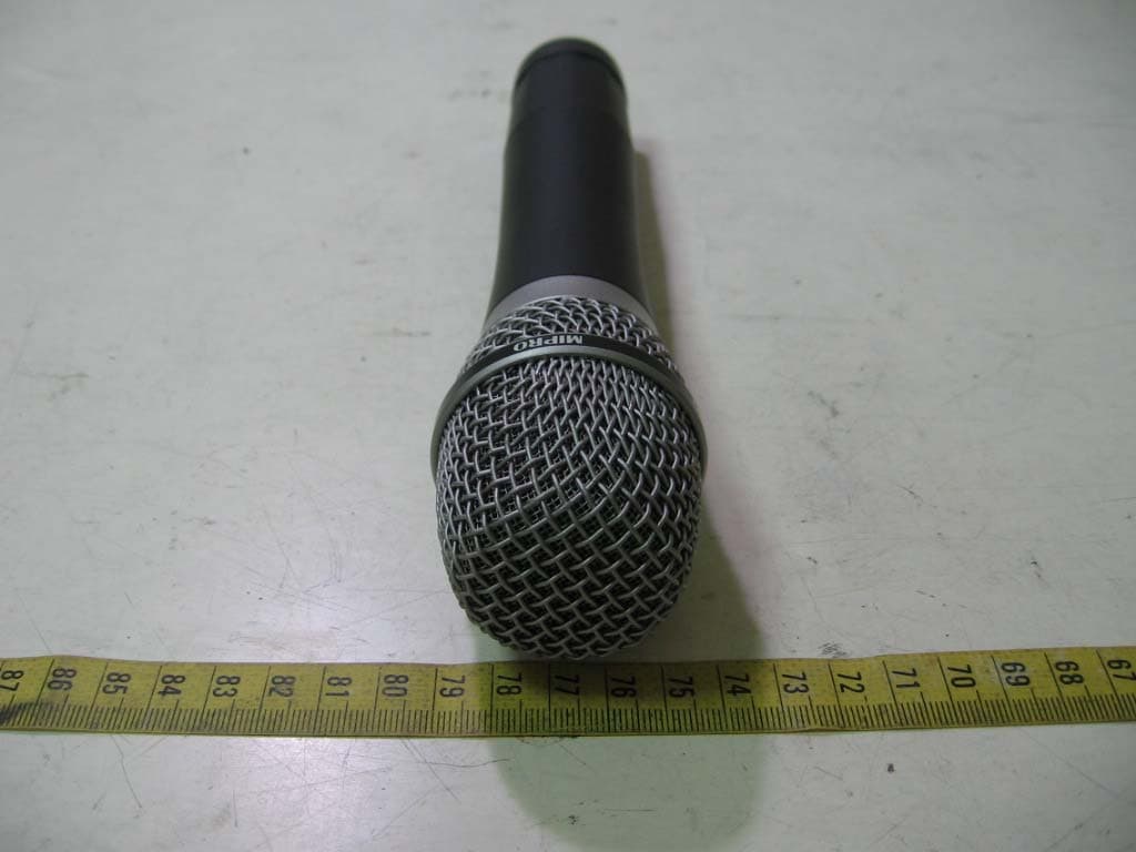
Click to zoom
Application Details
- Equipment Class
- TNF - Licensed Non-Broadcast Transmitter Held to Face
- Date of Grant
- Jul 31, 2006
- Application Purpose
- Original Equipment
- Date of Application
- Jul 31, 2006
- Equipment Note
- Handheld Wireless Microphone
- Frequency Range
- 614.00000000 - 806.00000000
- Company
- Mipro Electronics Co Ltd
- Country
- Taiwan
Documents & Files
Document Text
Text extracted from the exhibit documents filed with the FCC. Open a document above to read the original.
Users Manual
2CE216 MR-801a MR-801a OPERATINGMANUAL ElectronicsCo.,Ltd. Headoffice:814,Pei-KangRoad,Chiayi,60096,Taiwan. Taipeioffice:5,Lane118,Sung-tehRoad,Taipei,Taiwan. Web-http://www.mipro.com.tw E-mail:@mipro.com.tw 11075, mipro Disposal Disposetheunusabledeviceaccordingtovalidregulations. Disposalofspentbatteries/accumulators Youarerequiredbylawtoreturnallspentbatteries. Disposingofusedbatterieswithdomesticwasteis prohibited! Batteries/NiCadcellscontainingtoxinsare markedby accompanyingsymbolsthatrefertothe prohibitionof disposalwithdomesticwaste.Thedesignations forthe decisiveheavymetalsare:=cadmium, =mercury, =lead.Youmayreturnspent batteries/accumulatorsfree ofchargetotherecyclingcentres,ouroutletsor anywhere elsewherebatteries/accumulatorsaresold. Cd Hg Pb Bydoingso,youfulfilthelegalrequirementsandcontribute totheconservationofourenvironment! 2005-08-13 Half19-inchunit TrueDiversityWirelessMicrophoneSystem 12 ThankyouforselectingMIPROUHFhalf19-inchunittruediversity wirelessreceiversystem.Beforeoperatingpleasereadthisinstructionmanual carefullyandthoroughlyinordertoattainthecorrectoperatingproceduresand achievethebestresults. ThissystemisdividedintoUHFsinglechanneltruediversityreceiverwith matchingonemicrophonesandindividualvolumecontrols.Thissystemisalso equippedwith"NOISELOCK"squelchcircuit,andprovidestheefficacyfor eliminatetherandomnoiseinterferencewhenthereceiverisatstandbystate. (1)PowerSwitch&Indicator:Whenswitchisturnedon,redindicator illuminatestodenotenormalpowerstatus. (2)RFsignalIndicator:IndicatesreceivingtransmittingRFsignals. (3)AFsignalIndicator:Indicatesthemicrophonesignal. (4)ACInputJack:Toconnect85~265VoltsACpower. (5)DC12VInputJack:Toconnect12VDCfromtheAC/DCadapter. (6)AntennaInputConnectors:ForRearAntennaPlacement. (7)BalancedAudioOutputJack:WithCannon/XLRtypeconnector providesbalancedaudiooutputsignalfromthisjacktotheamplifier. (8)UnbalancedAudioOutputJack:With1/4"PhoneJackprovidesaudio outputsignalfromthisjacktotheamplifier. (9)UnbalancedLevelSwitch:"MIC"selectionisfor"Microphone-level" output."LINE"selectionisfor"Line-out"leveloutput. (10)SquelchAdjusters:AdjustthesquelchleveltoeliminatetheRFnoise interferenceatreceiverstand-bystate. (11)AntennaInputConnectors:ForrearAntennaPlacement. TRUEDIVERSITYWIRELESSRECEIVERTRUEDIVERSITYWIRELESSRECEIVER 1.PARTSNAMEANDFUNCTIONS A.FrontPanel AudioOutputCable1 Antenna2 InstructionManual1 AC/DCAdapter1orPowerCablex1 Thissystemincludesthefollowingaccessories: Fig.1 Fig.2 SIGNAL AFRF (1)(2)(3) (5) (4)(6) (6) (7) (7) (8) (8) (9) (9) (10) (10) (11) (11) (Withswitching powersupply) ANT.BANT.A MICLINE LEVELUNBALANCEDOUTBALANCEDOUT CEFCC 3:COLD- 1:GND + 2:HOT 3 21 SQ +- ANT.BANT.A MICLINE LEVEL UNBALANCEDOUTBALANCEDOUT CE FCC 3:COLD - 1:GND +2:HOT 3 21 SQ B.RearPanel 34 1.Installantennainrear(6)(11).Extendantennatothefullestposition.see fig.3. 2.PowerOutputConnection: 3.AudioOutputConnection: (a)ConnecttheAC/DCadaptercabletoDC12VINPUTJACK(5),then plugtheadapterunitintoanappropriateACoutletwithcautiontothe correctvoltageunderbothACoutletandadaptermarked,asshownin fig.4. (b)WiththeappropriateACpowercableconnectsfromACInputJack(4)to anACoutletunderthemarkedvoltage85~265V,asshowninfig.5. a)UnbalancedLevelSwitch(9)SettingPosition:Wheninputsthe unbalancedoutputofareceiverinto"Line-in"inputjackofamixeror amplifieror"ElectricGuitar",switchtheLevelSwitch(9)totheright "LINE"position.Lowsensitivitymayoccurifswitchtothewrong position.Wheninputtheunbalancedoutputofareceiverintothe"MIC- IN"inputjackofamixeroramplifier;switchtheLevelSwitch(9)tothe left"MIC"position.Overloaddistortionmayoccurifswitchtothewrong position.Whenusingelectricguitar,don'tuse"MIC"positionasitmay havegeneratedinsufficientlevel. (b)UnbalancedOutput:Usingaudiooutputcableattachedwith"PHONE PLUG"type,connectoneendfromtheunbalancedoutputjack(8)ofthe receiver,andtheotherendtothe"LINE-IN"inputjackoftheamplifier. (c)BalancedOutput:Usingaudiooutputcablesattachedwith"XLR"or "Cannon"type,connectoneendfromthebalancedoutputjacks(7)of thereceiver,andtheotherendtothe"MICIN"inputjackofthemixeror amplifier,asshowninFig.3.(Thecharacteristicofthe3-pinconnector isasshowninFig.6 (d)GuitarOutput:Usingaudiooutputcableattachedwith"PHONEPLUG" type,plugoneendfromtheunbalancedoutputjackofareceiver,and theotherendtotheinputjackofaguitaramplifier.SwitchtheLevel Switch(9)to"LINE"position. 2.INSTALLATIONOFTHERECEIVER TRUEDIVERSITYWIRELESSRECEIVERTRUEDIVERSITYWIRELESSRECEIVER ANT.BANT.A MICLINE LEVELUNBALANCEDOUTBALANCEDOUT CEFCC 3:COLD- 1:GND +2:HOT 3 21 SQ ANT.B +- ANT.B Fig.3 Fig.4Fig.5 Fig.6 3:COLD - + 1:GND 2:HOT 3 21 4.Makesurethesystemperformscorrectly, pleaseplacethesystemawayfromnoise sources.Placethereceiveratleast1 meterabovethegroundandawayfrom noisesources.Placethemicrophoneat least1meterawayfromthereceiving antenna,asshowninFig.9. 5.Withtworackmountbracketsinstalled, receivercanbemountedintoanEIA standardrackmountcase,asshownin Fig.10.Asanaccessory,youmay purchasefromnearestdealerafront antennakit,whichnotonlyallowseasy frontantennainstallation,butalso improvesefficiencyofsignalreception. 56 Fig.10 Fig.9 TRUEDIVERSITYWIRELESSRECEIVERTRUEDIVERSITYWIRELESSRECEIVER 3.TWO19/2-INCHUNITSRECEIVERINSTALLATION Fig.7 Fig.8 1.Singlehalf-rackreceiver (a)Pushtherackmountearoptionalaccessory(FB-11)upwards untilitisfirmlyattachedtothereceiver.(fig.7) 2.Dualhalf-rackreceivers (a)Positiontheconnectingplatesbetweenthetopandbottomof thetworeceiversandtighten.(Fig.8) (b)Afterjoiningthe2receiverstogether,pushtheoptional accessoryrackmountears(FB-12)upwardsuntiltheyfirmly attachedtothereceiver.(Fig.8) 3.Rack-mountkitAccessories: Rackmountkitfits1half-rack FB-11FB-12 Rackmountkitfits2 1half-rack half-rack or SIGNAL AFRF SIGNAL AFRF SIGNAL AFRF SIGNAL AFRF SIGNAL AFRF SIGNAL AFRF Ground TRUEDIVERSITYWIRELESSRECEIVERTRUEDIVERSITYWIRELESSRECEIVER 1.Turnvolumecontrolsofthereceiverandmixerinusetoaminimumsetting beforeturnonthemicrophonesortransmitters.Afterswitchesonthe receiver,thepowerswitchredindicatorilluminatestodenoteno…
Text truncated - open the document above for the full version.
Cover Letter(s)
910805 1 MIPRO ELECTRONICS CO., LTD. Headquarters: 814 Pei-Kang Road, Chiayi, 60096, TAIWAN. TEL: +(886)-5-238-0809 FAX: +(886)-5-238-0803 MICROPHONE PROFESSIONALS www.mipro.com.tw [email protected] Compliance Certification Services Certification Division 561F Monterey Road Morgan Hill, CA 95037 To whom it may concern: We, the undersigned, hereby authorize ELECTRONICS TESTING CENTER, TAIWAN, to act on our behalf in all manners relating to application for equipment authorization, including signing of all documents relating to these matters. Any and all acts carried out by ELECTRONICS TESTING CENTER, TAIWAN on our behalf shall have the same effect as acts of our own. We, the undersigned, hereby certify that we are not subject to a denial of federal benefits, that includes FCC benefits, pursuant to Section 5301 of the Anti-Drug Abuse Act of 1988, 21 U.S.C. 853(a). In authorizing ELECTRONICS TESTING CENTER, TAIWAN as our agent, we still recognize that we are responsible to: a) comply with the relevant provisions of the certification program; b) make all necessary arrangements for the conduct of the evaluation, including provision for examining documentation and access to all areas, records (including internal audit reports) and personnel for the purposes of evaluation (e.g. testing, inspection, assessment, surveillance, reassessment) and resolution of complaints; c) make claims regarding certification only in respect of the scope for which certification has been granted; d) do not use our product certification in such a manner as to bring the Certification Division into disrepute and not make any statement regarding our product certification which the Certification Division may consider misleading or unauthorized; 910805 2 e) upon suspension or cancellation of certification, discontinue use of all advertising matter that contains any reference thereto and return any certification documents as required by the Certification Division; f) use certification only to indicate the products are certified as being in conformity with specified standards; g) endeavor to ensure that no certificate or report nor any part thereof is used in a misleading manner; h) ensure that any reference to our product certification in communication media such as documents, brochures or advertising, complies with the requirements of the Certification Division; i) keep a record of all complaints made known to the us relating to the product’s compliance with requirements of the relevant standard and to make these records available to the Certification Division when requested; j) take appropriate action with respect to such complaints and any deficiencies found in products or services that affect compliance with the requirements for certification; k) document the actions taken. This authorization is valid until further written notice from the applicant. Sincerely Yours, Solomon Chang / President MIPRO Electronics Co., Ltd. 814 Pei-Kang Road, Chia-Yi, Taiwan
Cover Letter(s)
910805 3 MIPRO ELECTRONICS CO., LTD. Headquarters: 814 Pei-Kang Road, Chiayi, 60096, TAIWAN. TEL: +(886)-5-238-0809 FAX: +(886)-5-238-0803 MICROPHONE PROFESSIONALS www.mipro.com.tw [email protected] Federal Communications Commission FCC ID: M5XMH801A Product Name: Handheld Wireless Microphone Model Name: MH-801a Trade Name: MIPRO Dear Sir: In accordance with 47 C.F.R. Section 0.459, we would like to request confidentiality on some exhibits we submitted for above application for the reason of trade secret. If those exhibits are available for public inspection, any person who once gets the information contained in those exhibits will be able to design and to make the same products very easily. This is a very serious problem and huge loss for us, because we did invest so much on it. Please be not made the Exhibit Types listed below routinely available for public inspection: Block Diagram and Schematics, Operation Description and Tune-up Procedure. By: By: Solomon Chang (Signature) (Printed) Title : President Applicant : MIPRO Electronics Co., Ltd. Address : 814 Pei-Kang Road, Chia-Yi, Taiwan Tel : 886-5-238-0809 Fax: 886-5-238-0803 Date : Mar. 01, 2006
Cover Letter(s)
1 Helen Zhao Subject: FW: FW: MIPRO ELECTRONICS CO., LTD., FCC ID: M5XMH801A, Assessment NO.: AN06T5997, Notice#1 Exhibit-J-Conf_Lett er_rev.pdf Exhibit-C-Test_Rep ort-rev.pdf Exhibit-D-ID_Label_ rev.pdf Exhibit-B-Internal_p hotos-rev.... Exhibit-H-External_ Photos-rev.... Dear Helen, Pls find the revised documents for your reference. Best Regards, Iris Lin -----Original Message----- Sent: Friday, July 28, 2006 6:11 PM Subject: MIPRO ELECTRONICS CO., LTD., FCC ID: M5XMH801A, Assessment NO.: AN06T5997, Notice#1 Question #1: Based upon FCC2.926(d), "The equipment product code assigned by the grantee shall consist of a series of Arabic numerals, capital letters or a combination thereof, and may include the dash or hyphen (-). " Please note lower case is not allowed. Please revise FCC ID label format. Please also revise other documents in the filing that show incorrect FCC ID, e.g. test report, setup photos, external photos, internal photos, confidentiality letter. Best Regards, Helen Zhao The items indicated above must be submitted before processing can continue on the above referenced application. Failure to provide the requested information within 30 days of the original e-mail date may result in application dismissal and forfeiture of the filing fee. Also, please note that partial responses increase processing time and should not be submitted. Any questions about the content of this correspondence should be directed to the e-mail address listed below the name of the sender.
External Photos
ETC Report No.:06-02-RBF-045-01 FCC ID.: M5XMH801A Rev. 2.0 CONSTRUCTED PHOTOS of EUT Rear View of EUT Front View of EUT ETC Report No.:06-02-RBF-045-01 FCC ID.: M5XMH801A Rev. 2.0 CONSTRUCTED PHOTOS of EUT Side View of EUT Side View of EUT
Internal Photos
ETC Report No.:06-02-RBF-045-01 FCC ID.: M5XMH801A Rev. 2.0 CONSTRUCTED PHOTOS of EUT Internal View of EUT ETC Report No.:06-02-RBF-045-01 FCC ID.: M5XMH801A Rev. 2.0 CONSTRUCTED PHOTOS of EUT Component View of PCB Solder View of PCB
Test Report
Rev. 2.0 FCC Part 74 Subpart H EMI TEST REPORT of E.U.T. : Handheld Wireless Microphone FCC ID. : M5XMH801A MODEL : MH-801a Working Frequency : 614.000MHz-806.000MHz; for APPLICANT : MIPRO Electronics Co., Ltd. ADDRESS : 814 Pei-Kang Road, Chia-Yi, Taiwan Test Performed by ELECTRONICS TESTING CENTER, TAIWAN NO. 34, LIN 5, DING FU TSUN, LINKOU HSIANG TAIPEI HSIEN, TAIWAN, R.O.C. Tel:(02)226023052 Fax:(02)26010910 http://www.etc.org.tw ; e-mail : [email protected] Report Number : 06-02-RBF-045-01 ETC Report No.:06-02-RBF-045-01 FCC ID.: M5X-MH801A Rev. 2.0 TEST REPORT CERTIFICATION Applicant : MIPRO Electronics Co., Ltd. 814 Pei-Kang Road, Chia-Yi, Taiwan Manufacturer : MIPRO Electronics Co., Ltd. 814 Pei-Kang Road, Chia-Yi, Taiwan Description of EUT : a) Type of EUT : Handheld Wireless Microphone b) Trade Name : MIPRO c) Model No. : MH-801a d) FCC ID : M5XMH801A e) Working Frequency : 614.000MHz-806.000MHz f) Power Supply : DC 3Vdc Battery Regulation Applied : FCC Rules and Regulations Part 74 Subpart H (2005) I HEREBY CERTIFY THAT; The data shown in this report were made in accordance with the procedures given in ANSI C63.4 and the energy emitted by the device was founded to be within the limits applicable. I assume full responsibility for accuracy and completeness of these data. Issued Date : Apr. 13, 2006 Test Engineer : ( Vincent Chang ) Approve & Authorized Signer : Will Yauo, Manager EMC Dept. II of ELECTRONICS TESTING CENTER, TAIWAN ETC Report No.:06-02-RBF-045-01 FCC ID.: M5X-MH801A Rev. 2.0 Table of Contents Page 1. GENERAL INFORMATION ............................................................................................................................... 1 1.1 PRODUCT DESCRIPTION.......................................................................................................................................... 1 1.2 TEST METHODOLOGY............................................................................................................................................. 1 1.3 TEST FACILITY........................................................................................................................................................ 1 2. REQUIREMENTS OF PROVISIONS ................................................................................................................ 2 2.1 DEFINITION............................................................................................................................................................. 2 2.2 FREQUENCIES AVAILABLE...................................................................................................................................... 2 2.3 REQUIREMENTS FOR RADIO EQUIPMENT ON CERTIFICATION.................................................................................. 2 2.4 LABELING REQUIREMENT....................................................................................................................................... 3 3. OUTPUT POWER MEASUREMENT ................................................................................................................ 4 3.1 PROVISION APPLICABLE......................................................................................................................................... 4 3.2 MEASUREMENT PROCEDURE................................................................................................................................... 4 3.3 TEST DATA............................................................................................................................................................. 6 3.4 RESULT CALCULATION........................................................................................................................................... 7 3.5 TEST EQUIPMENT.................................................................................................................................................... 7 4. MODULATION CHARACTERISTICS ............................................................................................................. 8 4.1 PROVISIONS APPLICABLE........................................................................................................................................ 8 4.2 MEASUREMENT METHOD........................................................................................................................................ 8 4.3 MEASUREMENT INSTRUMENT................................................................................................................................. 9 4.4 MEASUREMENT RESULT......................................................................................................................................... 9 5. OCCUPIED BANDWIDTH OF EMISSION .................................................................................................... 11 5.1 PROVISIONS APPLICABLE...................................................................................................................................... 11 5.2 MEASUREMENT METHOD...................................................................................................................................... 11 5.3 OCCUPIED BANDWIDTH TEST EQUIPMENT............................................................................................................ 11 5.4 BANDWIDTH MEASURED...................................................................................................................................... 12 5.4.1 Input Level Derived...................................................................................................................................... 12 5.4.2 Occupied Bandwidth Plotted........................................................................................................................ 13 6. FIELD STRENGTH OF EMISSION................................................................................................................. 14 6.1 PROVISIONS APPLICABLE...…
Text truncated - open the document above for the full version.
Test Setup Photos
ETC Report No.:06-02-RBF-045-01 FCC ID.:M5XMH801A Rev. 2.0 Radiated Measurement Photos Mode: TX
Contact Information
Applicant
Solomon Chang
Test Firm
Electronics Testing Center, TaiwanWill Yauo
Technical Specifications
| # | Rule Parts | Frequency Range | Power Output | Emission | Tolerance |
|---|---|---|---|---|---|
| 1 | 74 | 614 MHz - 806 MHz | 9.12 mW | 116KF3E | 0.0050000000 % |
Other Applications from Mipro Electronics Co Ltd

M5X-MT58A
Jun 05, 2026Transmitter
Equipment Class
NII - Unlicensed National Information Infrastructure TX
M5X-ACT33TW
Dec 22, 2025TRANSMITTER
Equipment Class
DWM - Part 15 Wireless Microphone
M5X-ACT240T
Jul 26, 2021Transmitter
Equipment Class
DTS - Digital Transmission System
M5X-MTM24
Jul 11, 2021Wireless Transmitter
Equipment Class
DTS - Digital Transmission System
M5X-MTM58
Jul 11, 2021Wireless Transmitter
Equipment Class
NII - Unlicensed National Information Infrastructure TX