M7G-264524CSingle Directional Amplifier
EMR Corporation
Click to zoom
Application Details
- Equipment Class
- AMP - Amplifier
- Date of Grant
- May 26, 2003
- Application Purpose
- Original Equipment
- Date of Application
- May 26, 2003
- Equipment Note
- Single Directional Amplifier
- Frequency Range
- 440.01050000 - 469.98950000
- Company
- EMR Corporation
- Country
- United States
Documents & Files
Document Text
Text extracted from the exhibit documents filed with the FCC. Open a document above to read the original.
External Photos
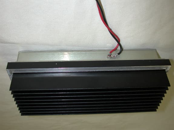
EXTERNAL PHOTOS
Internal Photos
INTERNAL PHOTOS
Parts List/Tune Up Info
Tuneup Procedure This device does not have any adjustment. The rf gain and maximum rf output power are set during the manufacturing process and cannot be changed by the end user.
RF Exposure Info
Prediction of MPE limit at a given distance Equation from page 18 of OET Bulletin 65, Edition 97-01 where:S = power density P = power input to the antenna G = power gain of the antenna in the direction of interest relative to an isotropic radiator R = distance to the center of radiation of the antenna Maximum peak output power at antenna input terminal:37.80(dBm) Maximum peak output power at antenna input terminal:6025.595861(mW) Antenna gain(typical):12(dBi) Maximum antenna gain:15.84893192(numeric) Prediction distance:200(cm) Prediction frequency:450(MHz) MPE limit for uncontrolled exposure at prediction frequency:0.3(mW/cm^2) Power density at prediction frequency:0.189990(mW/cm^2) Margin of compliance:-2.0(dB) 2 4R PG S π =
Test Report
Master: ktlPT90PLMR Date: April 19, 1999 Nemko Test Report: 2L0611RUS1 Applicant: EMR Corporation 5 Circle Freeway Drive Cincinnati, OH 45246 Equipment Under Test: 264524C Series (E.U.T.) In Accordance With: FCC Part 90, Subpart I & Part 22, Subpart E Amplifier Tested By: Nemko Dallas Inc. 802 N. Kealy Lewisville, TX 75057-3136 Authorized By: Tom Tidwell, Frontline Manager Date: 5/6/03 Total Number of Pages: 27 Nemko Dallas FCC PART 90, Subpart I & Part 22, Subpart E Amplifier EQUIPMENT: 264524C Series Test Report Number 2L0611RUS1 Page 2 of 27 Table of Contents Section 1. Summary of Test Results.................................................................................................3 Section 2. General Equipment Specification......................................................................................5 Section 3. RF Power Output.............................................................................................................7 Section 4. Occupied Bandwidth........................................................................................................8 Section 5. Spurious Emissions at Antenna Terminals......................................................................11 Section 6. Field Strength of Spurious Emissions..............................................................................15 Section 7. Test Equipment List.......................................................................................................18 ANNEX A - TEST METHODOLOGIES.............................................................................................19 ANNEX B - TEST DIAGRAMS.........................................................................................................24 Nemko Dallas FCC PART 90, Subpart I & Part 22, Subpart E Amplifier EQUIPMENT: 264524C Series Test Report Number 2L0611RUS1 Page 3 of 27 Section 1. Summary of Test Results Manufacturer: EMR Corporation Model No.: 264524C Serial No.: None General: All measurements are traceable to national standards. These tests were conducted on a sample of the equipment for the purpose of demonstrating compliance with FCC Part 90, Subpart I and Part 22, Subpart E New Submission Production Unit Class II Permissive Change Pre-Production Unit A M P Equipment Code THIS TEST REPORT RELATES ONLY TO THE ITEM(S) TESTED. THE FOLLOWING DEVIATIONS FROM, ADDITIONS TO, OR EXCLUSIONS FROM THE TEST SPECIFICATIONS HAVE BEEN MADE. NONE Nemko Dallas Inc. authorizes the above named company to reproduce this report provided it is reproduced in its entirety and for use by the company’s employees only. Any use which a third party makes of this report, or any reliance on or decisions to be made based on it, are the responsibility of such third parties. Nemko Dallas Inc. accepts no responsibility for damages, if any, suffered by any third party as a result of decisions made or actions based on this report. This report applies only to the items tested. Nemko Dallas FCC PART 90, Subpart I & Part 22, Subpart E Amplifier EQUIPMENT: 264524C Series Test Report Number 2L0611RUS1 Page 4 of 27 Summary Of Test Data NAME OF TEST PARA. NO. RESULT RF Power Output 90.205 22.565 Complies Audio Frequency Response TIA EIA- 603.3.2.6 N/A Audio Low-Pass Filter Response TIA EIA- 603.3.2.6 N/A Modulation Limiting TIA EIA- 603.3.2.6 N/A Occupied Bandwidth 90.210 22.561 Complies Spurious Emissions at Antenna Terminals 90.210 Complies Field Strength of Spurious Emissions 90.210 Complies Frequency Stability 90.213 N/A Transient Frequency Behavior 90.214 N/A Footnotes For N/A’s: (1) Since the E.U.T. does not contain modulation circuitry modulation testing was not performed. (2) Since the E.U.T. is not a keyed carrier system, Transient Frequency Behavior was not performed. (3) Since the E.U.T. processes but does not produce a signal, frequency stability was not tested. . Nemko Dallas FCC PART 90, Subpart I & Part 22, Subpart E Amplifier EQUIPMENT: 264524C Series Test Report Number 2L0611RUS1 Page 5 of 27 Section 2. General Equipment Specification Transmitter Supply Voltage Input: 13.6 Vdc Frequency Range: 440.0105 to 469.9895 MHz Type(s) of Modulation: F3E F1D F2D D7W (QAM) Other Emission Designator: 25K0F3E Output Impedance: 50 ohms RF Power Output (rated): Single: 6 Watts Composite: N/A (The EUT will have channel filters installed upon installation) Operator Selection of Operating Frequency: Channel filter (end user) Power Output Adjustment Capability: None Frequency Translation: F1-F1 F1-F2 N/A Band Selection: Software Duplexer Change Fullband Coverage Nemko Dallas FCC PART 90, Subpart I & Part 22, Subpart E Amplifier EQUIPMENT: 264524C Series Test Report Number 2L0611RUS1 Page 6 of 27 Theory of Operation The 264524C Series of EMR amplifiers are intended for use in low power amplification and reamplification systems. Applications include land mobile radio bi- and uni directional signal booster systems. System Diagram Nemko Dallas FCC PART 90, Subpart I & Part 22, Subpart E Amplifier EQUIPMENT: 264524C Series Test Report Number 2L0611RUS1 Page 7 of 27 Section 3. RF Power Output NAME OF TEST: RF Power Output PARA. NO.: 2.1046 TESTED BY: David Light DATE: 4/21/03 Test Results: Complies. Measurement Data: Frequency (MHz) Measured Power (dBm/Watts) Rated Power (dBm/Watts) 455 37.8 / 6.0 37.8 / 6.0 Note: Output power was tested at +/- 15% voltage variation with no effect on output power. Test equipment used: 1036 Measurement uncertainty: +/- 1.7 dB Temperature: 22 O C Relative humidity: 40% Nemko Dallas FCC PART 90, Subpart I & Part 22, Subpart E Amplifier EQUIPMENT: 264524C Series Test Report Number 2L0611RUS1 Page 8 of 27 Section 4. Occupied Bandwidth NAME OF TEST: Occupied Bandwidth PARA. NO.: 2.1049 TESTED BY: David Light DATE: 4/21/03 Test Results: Complies. Test Data: See attached graph(s). Test equipment used: 1036-1604-1064-1627 Measurement uncertainty: +/- 1.7 dB Temperature: 22 O C Relative humidity: 40% Nemko Dallas FCC PART 90, Subpa…
Text truncated - open the document above for the full version.
Test Setup Photos
TEST-SET UP PHOTOS
Contact Information
Applicant
William F Lieske(President)
Technical Contact
Non-Technical Contact
Nemko DallasSusan Griffith
[email protected]972-436-9600
Test Firm
Nemko Dallas, Inc.Michael Cantwell
Technical Specifications
| # | Rule Parts | Frequency Range | Power Output | Emission | Tolerance |
|---|---|---|---|---|---|
| 2 | 9 | 440.0105 MHz - 469.9895 MHz | 6 W | F3E | Amp |
Other Applications from EMR Corporation
M7G-264424C
May 26, 2003Single Direction Amplifier
Equipment Class
AMP - Amplifier
M7G-HUHF800-40
Apr 03, 2001Commercial Linear Amplifier
Equipment Class
AMP - Amplifier
M7G-VHF150-30
Mar 09, 2000RF Power Amplifer
Equipment Class
AMP - Amplifier
M7G-VHF150-60
Mar 07, 2000RF Power Amplifier
Equipment Class
AMP - Amplifier
M7G-VHF150-100
Mar 07, 2000RF Power Amplifier
Equipment Class
AMP - Amplifier