M7G-HUHF800-40Commercial Linear Amplifier
EMR Corporation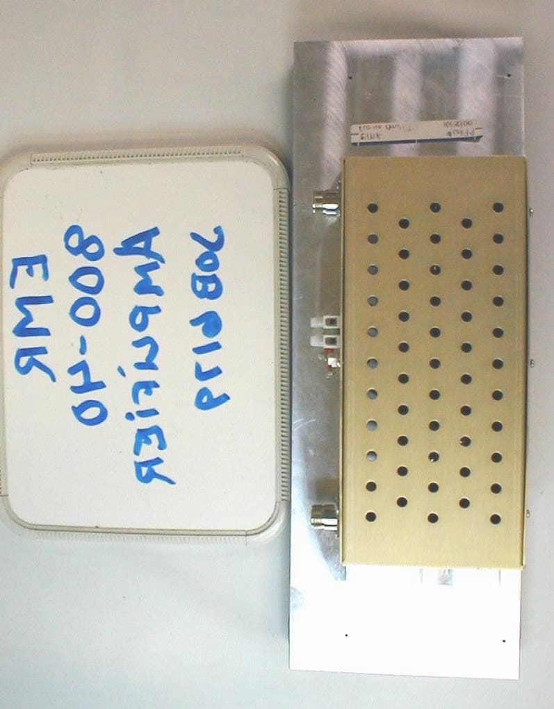
Click to zoom
Application Details
- Equipment Class
- AMP - Amplifier
- Date of Grant
- Apr 03, 2001
- Application Purpose
- Original Equipment
- Date of Application
- Apr 03, 2001
- Equipment Note
- Commercial Linear Amplifier
- Frequency Range
- 850.00000000 - 875.00000000
- Company
- EMR Corporation
- Country
- United States
Documents & Files
Document Text
Text extracted from the exhibit documents filed with the FCC. Open a document above to read the original.
Users Manual
HUHF800-40SERIES 850-875MHzAMPS FCCCertificationID# M7G-HUHF800-40 TableofContents PRODUCTDESCRIPTION............................ GENERALSPECIFICATIONS......................... CIRCUITDESCRIPTIONS............................. SCHEMATICS............................................. PARTSLIST................................................ WARRANTYINFORMATION......................... TheHUHF800-40SeriesofEMRamplifiersare intendedforuseincommercialcommunications systems.Applicationsincludecellular,SMRtrunking anddatasystems.Theywillcoverthefrequency rangeextendingfrom850MHzto875MHz. Foroperatorconvenience,viewsofthe Amplifierarepresentedhere.. FCCCertification LabelPlacement 850-875 13.640watts M7G-HUHF800-40 HUHF800-40 FREQUENCYRANGE:850-875MHz OPERATINGMODE:FM USAGE:SingleChannelSystems MODEL#:HUHF800-40 OUTPUTPOWER:40WATTS OPERATING TEMPERATURERANGE:-20to+60Deg.C OPERATINGVOLTAGE:+13.6VDC/8amps DUTYCYCLE:100% HARMONICMeetsFCC ATTENUATION:Certification OPTIONS:EMRAmplifiersareavailable Withseveralmechanical mountingoptionsandin Variousconfigurations. (Specifiedattimeoforder.) FCC Certification LABEL 850-875 13.6 40watts M7G-HUHF800-40 HUHF800-40 TheHUHF800-40Seriespoweramplifierisaself- containedrackmountableunitcapableofupto40 wattsofclasscoutputpower,withbuiltincooling circuitryandpowerreductioncapability.Theinput signalisamplifiedbyapowermodulecapableof producing14watts.Itisthensplitandamplifiedby theoutputamplifiersandrecombinedwitha Wilkinsoncombiner.Finally,itisfilteredbyaseven elementlowpassfilter. 40WATTSMRAMP BillofMaterialsAug.1,2000 ITEMQUANTITYREFERENCEPART ___________________________________________________ 12C1,C84.3PF 22C2,C347PF 31C4.01UF 41C52.2UF 53C6,C12,C2313PF 62C7,C133PF 72C9,C212.2PF 82C10,C1122PF 91C1415PF 101C156.8PF 111C16270PF 121C17100PF 131C1810PF 142C19,C2018PF 151C22150PF 162J1,J2TYPEN 171L13.5T 183L2,L3,L412NH 194L5,L7,L8,L94.5T 201L6VK/4B 211Q1MRF847 221Q2MRF842 232R1,R220 244Z1,Z2,Z3,Z4u-STRIP Forserviceonthisamplifier,contact: EMRCorporation EMRCorporation,hereinaftercalledEMR,warrants thatallequipmentofitsmanufactureshallbefreefromdefects indesign,materialsandworkmanshipforaperiodof12months fromdateofshipmentsunlessotherwisecoveredbyspecial warranty.Ifanysuchproduct,entirelyorinpart,failstoproduce theperformancesetforthinthebrochures,quotationsor literatureprovidedbyEMR,suchproductwillbereplacedor repairedatEMR’sexpenseprovidedthatthefailurewasnotthe resultofalteration,misuse,tampering,misapplication,shipping damageorvandalism.Ifaproductfailureisfoundtobethe faultofEMR,costsoftransportationtotheEMRfactoryand returnwillbebornbyEMR.ShouldEMRsupplycomponentsnot ofitsownmanufacture,butspecifiedbyacustomer,the warrantyshallreflecttheoriginalmanufactureswarranty,only. ItisunderstoodthatthisstatementconstitutesEMR’sentire andonlywarranty,therebeingnootherwarranteesexpressedor impliedinlaworinfact,includingimpliedwarranteesoffitness. InnoeventshallEMRbeliablefordamageseitherdirector consequential,thatmaybeoccasionedbyanydefectin materials,workmanshiporproductsupport. 22402N.19thAvenue Phoenix,Arizona85021 Tel:623/581/2875800/796/2875 E-mail:[email protected] http://www.emrcorp.com FAX:623/582/9499
Cover Letter(s)
To: Bill Graff From: Greg Snyder Date: 3/27/01 Reference: FCC ID: M7G-HUHF800-40 1.) All amplifiers will need the three tone intermod test. This has been FCC policy for years. R. This unit is only used as a single channel amplifier and therefore the IM test is not required. See e-mail excerpt from Frank Coperich below: From: Frank Coperich [mailto:[email protected]] Sent: Wednesday, March 21, 2001 11:08 AM To: [email protected] Cc: Raymond Laforge Subject: Re: Question on Amplifier Testing The (three tone) IM test does not apply to single channel amplifiers. 2.) Transmitter radiated spurious must be done using the substitution method as described in TIA/EIA 603, and not just a field strength measurement converted to ERP. R. Radiated spurious emissions have been measured using the signal substitution method. See revised report dated 3/27/01. 3.) The measured power output on the 731 does not seem to track with the power output listed in 3.1. Voltage vs. power is not necessarily a concern, therefore testing at anything other than STV (Standard Test Voltage) is confusing. Is this variation in power due to the characteristics of the exciter or the amp? A table including the output power of the exciter feeding the amp on this table is helpful. R. The output power was re-measured with and a new data table has been inserted in the revised report dated 3/27/01. The input signal was also verified to be at a level of 2 watts for each frequency. 4.) It is useful to include unmodulated plots with all Occupied Bandwidths. Ideally, unmodulated plots would always be set to the top of the reference level before modulation applied. As a bonus, if the cable and attenuator loss are placed into the spectrum analyzer offset, then Reference Level would equal power output in dBm. R. Future submissions will include the unmodulated signal with the Occupied Bandwidth plots. 5.) No RF exposure information is included. There are no instructions as to where this device could be installed. Therefore, it cannot even be identified properly as either Fixed or Mobile. Please address. R. The amplifier is used as fixed basestation applications.
External Photos
Exterior Photos
ID Label/Location Info
TheHUHF800-40SeriesofEMRamplifiersare intendedforuseincommercialcommunications systems.Applicationsincludecellular,SMRtrunking anddatasystems.Theywillcoverthefrequency rangeextendingfrom850MHzto875MHz. Foroperatorconvenience,viewsofthe Amplifierarepresentedhere.. FCCCertification LabelPlacement 850-875 13.640watts M7G-HUHF800-40 HUHF800-40 FREQUENCYRANGE:850-875MHz OPERATINGMODE:FM USAGE:SingleChannelSystems MODEL#:HUHF800-40 OUTPUTPOWER:40WATTS OPERATING TEMPERATURERANGE:-20to+60Deg.C OPERATINGVOLTAGE:+13.6VDC/8amps DUTYCYCLE:100% HARMONICMeetsFCC ATTENUATION:Certification OPTIONS:EMRAmplifiersareavailable Withseveralmechanical mountingoptionsandin Variousconfigurations. (Specifiedattimeoforder.) FCC Certification LABEL 850-875 13.6 40watts M7G-HUHF800-40 HUHF800-40
Internal Photos
Cover Removed Enclosure Removed From Heat Sink Top View of PCB Bottom View of PCB
Operational Description
TheHUHF800-40Seriespoweramplifierisaself- containedrackmountableunitcapableofupto40 wattsofclasscoutputpower,withbuiltincooling circuitryandpowerreductioncapability.Theinput signalisamplifiedbyapowermodulecapableof producing14watts.Itisthensplitandamplifiedby theoutputamplifiersandrecombinedwitha Wilkinsoncombiner.Finally,itisfilteredbyaseven elementlowpassfilter.
Parts List/Tune Up Info
40WATTSMRAMP BillofMaterialsAug.1,2000 ITEMQUANTITYREFERENCEPART ___________________________________________________ 12C1,C84.3PF 22C2,C347PF 31C4.01UF 41C52.2UF 53C6,C12,C2313PF 62C7,C133PF 72C9,C212.2PF 82C10,C1122PF 91C1415PF 101C156.8PF 111C16270PF 121C17100PF 131C1810PF 142C19,C2018PF 151C22150PF 162J1,J2TYPEN 171L13.5T 183L2,L3,L412NH 194L5,L7,L8,L94.5T 201L6VK/4B 211Q1MRF847 221Q2MRF842 232R1,R220 244Z1,Z2,Z3,Z4u-STRIP
Schematics
HUHF800-40SERIES 850-875MHzAMPS FCCCertificationID# M7G-HUHF800-40 TableofContents PRODUCTDESCRIPTION............................ GENERALSPECIFICATIONS......................... CIRCUITDESCRIPTIONS............................. SCHEMATICS............................................. PARTSLIST................................................ WARRANTYINFORMATION......................... TheHUHF800-40SeriesofEMRamplifiersare intendedforuseincommercialcommunications systems.Applicationsincludecellular,SMRtrunking anddatasystems.Theywillcoverthefrequency rangeextendingfrom850MHzto875MHz. Foroperatorconvenience,viewsofthe Amplifierarepresentedhere.. FCCCertification LabelPlacement 850-875 13.640watts M7G-HUHF800-40 HUHF800-40 FREQUENCYRANGE:850-875MHz OPERATINGMODE:FM USAGE:SingleChannelSystems MODEL#:HUHF800-40 OUTPUTPOWER:40WATTS OPERATING TEMPERATURERANGE:-20to+60Deg.C OPERATINGVOLTAGE:+13.6VDC/8amps DUTYCYCLE:100% HARMONICMeetsFCC ATTENUATION:Certification OPTIONS:EMRAmplifiersareavailable Withseveralmechanical mountingoptionsandin Variousconfigurations. (Specifiedattimeoforder.) FCC Certification LABEL 850-875 13.6 40watts M7G-HUHF800-40 HUHF800-40 TheHUHF800-40Seriespoweramplifierisaself- containedrackmountableunitcapableofupto40 wattsofclasscoutputpower,withbuiltincooling circuitryandpowerreductioncapability.Theinput signalisamplifiedbyapowermodulecapableof producing14watts.Itisthensplitandamplifiedby theoutputamplifiersandrecombinedwitha Wilkinsoncombiner.Finally,itisfilteredbyaseven elementlowpassfilter. 40WATTSMRAMP BillofMaterialsAug.1,2000 ITEMQUANTITYREFERENCEPART ___________________________________________________ 12C1,C84.3PF 22C2,C347PF 31C4.01UF 41C52.2UF 53C6,C12,C2313PF 62C7,C133PF 72C9,C212.2PF 82C10,C1122PF 91C1415PF 101C156.8PF 111C16270PF 121C17100PF 131C1810PF 142C19,C2018PF 151C22150PF 162J1,J2TYPEN 171L13.5T 183L2,L3,L412NH 194L5,L7,L8,L94.5T 201L6VK/4B 211Q1MRF847 221Q2MRF842 232R1,R220 244Z1,Z2,Z3,Z4u-STRIP Forserviceonthisamplifier,contact: EMRCorporation EMRCorporation,hereinaftercalledEMR,warrants thatallequipmentofitsmanufactureshallbefreefromdefects indesign,materialsandworkmanshipforaperiodof12months fromdateofshipmentsunlessotherwisecoveredbyspecial warranty.Ifanysuchproduct,entirelyorinpart,failstoproduce theperformancesetforthinthebrochures,quotationsor literatureprovidedbyEMR,suchproductwillbereplacedor repairedatEMR’sexpenseprovidedthatthefailurewasnotthe resultofalteration,misuse,tampering,misapplication,shipping damageorvandalism.Ifaproductfailureisfoundtobethe faultofEMR,costsoftransportationtotheEMRfactoryand returnwillbebornbyEMR.ShouldEMRsupplycomponentsnot ofitsownmanufacture,butspecifiedbyacustomer,the warrantyshallreflecttheoriginalmanufactureswarranty,only. ItisunderstoodthatthisstatementconstitutesEMR’sentire andonlywarranty,therebeingnootherwarranteesexpressedor impliedinlaworinfact,includingimpliedwarranteesoffitness. InnoeventshallEMRbeliablefordamageseitherdirector consequential,thatmaybeoccasionedbyanydefectin materials,workmanshiporproductsupport. 22402N.19thAvenue Phoenix,Arizona85021 Tel:623/581/2875800/796/2875 E-mail:[email protected] http://www.emrcorp.com FAX:623/582/9499
Test Report
FCC CERTIFICATION REPORT prepared for EMR Corporation 22402 North 19 th Avenue Phoenix, AZ 85027 FCC ID: M7G-HUHF 800-40 March 27, 2001 WLL PROJECT #: 6179X This report shall not be reproduced, except in full, without the prior written consent of Washington Laboratories, Ltd. EMR Corporation M7G-UHF 450-70 WLL Project # 4717X i TABLE OF CONTENTS Statement of Qualifications Letter of Agency ________________________________________________ 1.0 INTRODUCTION..............................................................................................................................................3 1.1 SUMMARY......................................................................................................................................................... 3 2.0 DESCRIPTION OF EQUIPMENT UNDER TEST (EUT)............................................................................3 3.0 TEST CONFIGURATION................................................................................................................................4 3.1 RF OUTPUT POWER (FCC RULE PART 2.1046)............................................................................................... 4 3.2 MODULATION CHARACTERISTICS (FCC RULE PART 2.1047).......................................................................... 4 3.3 OCCUPIED BANDWIDTH (FCC RULE PART 2.1049)......................................................................................... 4 3.4 SPURIOUS EMISSIONS AT ANTENNA TERMINALS (FCC RULE PART 2.1051)................................................... 7 3.5 RADIATED EMISSIONS TESTING (FCC RULE PART 2.1053)........................................................................... 12 3.6 FREQUENCY STABILITY (FCC RULE PART 2.1055)....................................................................................... 14 3.7 TRANSIENT FREQUENCY BEHAVIOR (FCC PART 90.214).............................................................................. 14 TABLES Table 1. Radiated Emissions Data Table 2. Measurement Equipment Used APPENDICES: Appendix A Statement of Measurement Uncertainty EMR Corporation M7G-UHF 450-70 WLL Project # 4717X ii STATEMENT OF QUALIFICATIONS for Santo V. Lavorata Washington Laboratories, Ltd. I have fifteen years of EMC/EMI, RF and microwave testing experience, with the last seven years as an EMC Test Engineer. I hold a Bachelor of Science in Electronics Engineering Technology. I am qualified to perform EMC testing to the methods described in this test report. The measurements taken within this report are accurate within my ability to perform the tests and within the tolerance of the measuring instrumentation. By: ________________________ Santo V. Lavorata Compliance Engineer Date: January 17, 2001 EMR Corporation M7G-UHF 450-70 WLL Project # 4717X 3 FCC CERTIFICATION REPORT For EMR Corporation 1.0 Introduction This report has been prepared on behalf of EMR Corporation in support of their application for FCC Certification under Part 90 of the FCC Rules and Regulations. The Equipment Under Test was a Rack Mounted UHF Power Amplifier (Model: HUHF 800-40). All measurements were performed at Washington Laboratories, Ltd. test center in Gaithersburg, MD. Site description and site attenuation data have been placed on file with the FCC's Sampling and Measurements Branch at the FCC laboratory in Columbia, MD. Washington Laboratories has been accepted by the FCC and approved by NIST NVLAP (NVLAP Lab Code 200066-0) as an independent FCC test laboratory. Measurements were made on the Equipment Under Test in accordance with FCC Rule Part 2, specifically the requirements stipulated in: 2.1046 RF Power Output 2.1047 Modulation Characteristics 2.1049 Occupied Bandwidth 2.1051 Spurious Emissions at Antenna Terminals 2.1053 Field Strength of Spurious Radiation 2.1055 Frequency Stability All results reported herein relate only to the item tested. This report shall not be used to claim product endorsement by NVLAP or any agency of the US Government. The measurement uncertainty of the data contained herein is ±2.3 dB. Refer to Appendix A for Statement of Measurement Uncertainty. 1.1 Summary The UHF Amplifier complies with the technical requirements of Part 90 of the FCC Rules and Regulations. 2.0 Description of Equipment Under Test (EUT) The UHF Amplifier series is intended for use in commercial communication systems. Applications include land mobile repeaters, trunking, and data systems. The amplifier is a 40-watt power amplifier operating in the frequency range of 850-875 MHz. The amplifier is powered by an externally supplied 13.6 VDC power source. Testing was performed at the low, middle, and high frequencies of operation for the amplifier. EMR Corporation M7G-UHF 450-70 WLL Project # 4717X 4 3.0 Test Configuration 3.1 RF Output Power (FCC Rule Part 2.1046) A 2 Watt unmodulated carrier signal was connected to the input of the UHF amplifier. The output from the amplifier was connected to a 40 Watt attenuator and then to the input of an HP 8564E RF Spectrum Analyzer. The analyzer offset was adjusted to compensate for the 40 dB attenuator. The RF output power across a 50 ohm load termination was measured directly by the analyzer. The following table lists the measured output power. Frequency (MHz) Input Power to Amplifier Power Output at Nominal Voltage (13.6 Vdc) 850 2 Watts 40.7 Watts 862 2 Watts 38.9 Watts 875 2 Watts 44.7 Watts 3.2 Modulation Characteristics (FCC Rule Part 2.1047) The EUT is an amplifier only and contains no circuitry to modify the RF signal supplied from an approved radio. Only the power level will be raised. 3.3 Occupied Bandwidth (FCC Rule Part 2.1049) A 2 Watt, 2.5 kHz FM modulated signal with 5 kHz FM deviation was connected to the input of the amplifier and the occupied bandwidth observed. A plot depicting the Occupied Bandwidth of the input signal followed by a plot showing the Occupied Bandwidth of the amplifier signal are shown in Figures 1 and 2. EMR Corporation M7G…
Text truncated - open the document above for the full version.
Test Setup Photos
Test Setup Photos
Contact Information
Applicant
William F Lieske(President)
Technical Contact
Washington Laboratories LimitedGregory M Snyder
[email protected]301 417 0220
7560 Lindbergh Drive · Gaithersburg, Maryland · United States
Test Firm
Washington Laboratories, Ltd.Michael Violette
Technical Specifications
| # | Rule Parts | Frequency Range | Power Output | Emission |
|---|---|---|---|---|
| 1 | 22,90 | 850 MHz - 875 MHz | 40 W | F3E |
Other Applications from EMR Corporation
M7G-264424C
May 26, 2003Single Direction Amplifier
Equipment Class
AMP - Amplifier
M7G-264524C
May 26, 2003Single Directional Amplifier
Equipment Class
AMP - Amplifier
M7G-VHF150-30
Mar 09, 2000RF Power Amplifer
Equipment Class
AMP - Amplifier
M7G-VHF150-60
Mar 07, 2000RF Power Amplifier
Equipment Class
AMP - Amplifier
M7G-VHF150-100
Mar 07, 2000RF Power Amplifier
Equipment Class
AMP - Amplifier