MAA-PW8610IM802.11 b/g Wireless LAN Cardbus
Procomp Informatics Ltd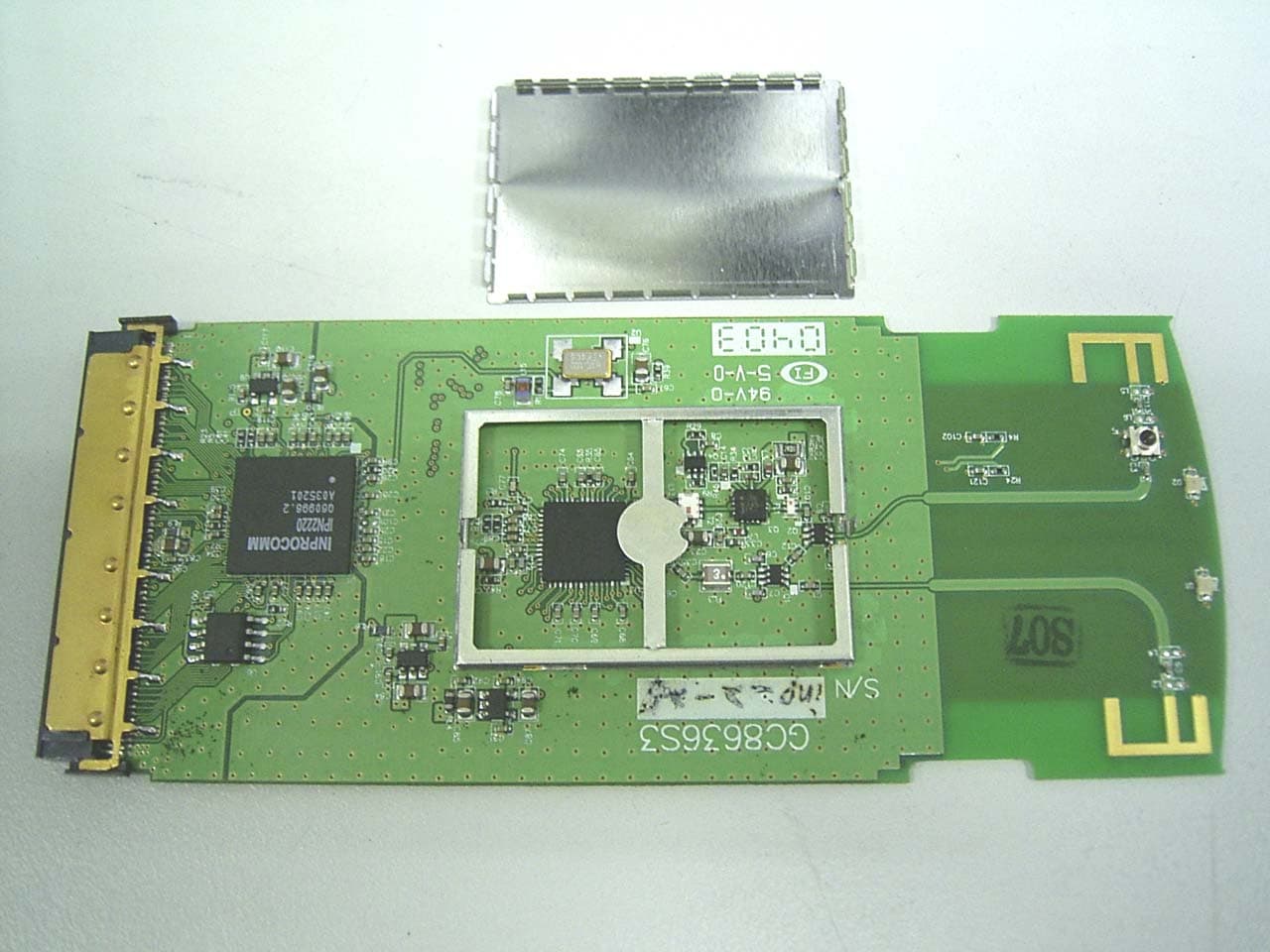
Click to zoom
Application Details
- Equipment Class
- DTS - Digital Transmission System
- Date of Grant
- Apr 26, 2004
- Application Purpose
- Original Equipment
- Date of Application
- Apr 26, 2004
- Equipment Note
- 802.11 b/g Wireless LAN Cardbus
- Frequency Range
- 2412.00000000 - 2462.00000000
- Company
- Procomp Informatics Ltd
- Country
- Taiwan
Documents & Files
Document Text
Text extracted from the exhibit documents filed with the FCC. Open a document above to read the original.
Users Manual
User Guide for Procomp WLAN Solution IEEE 802.11b/g Wireless Network Adapte r Procomp Informatics Ltd. 2 Preface This user's guide provides the necessary information for first-time users to successfully install the Procomp network driver interface specification (NDIS) driver, for the purpose of evaluating and/or operating the Procomp WLAN card solution for IEEE 802.11b/g in a Microsoft Windows environment and the Procomp WLAN Driver and Utility. This guide also provides information for users who wish to upgrade the Procomp NDIS driver from previous releases. This guide describes the steps required to install NDIS drivers for the Procomp Wireless Network Adapter in Windows 2000, Windows XP, Windows Millennium Edition, Windows 98SE. About this Document Chapter 1 Introduction—Hardware, software, and system requirements needed to set up the Procomp Wireless Network Adapter. Chapter 2 Installation—Installation/uninstallation procedures for Windows XP, Windows 2000, Windows ME, Windows 98SE. 3 1 Introduction The Procomp Wireless Network Adapters are designs based on the Inprocomm IPN2220 and Maxim 2825 chip set. These designs implement a half-duplex, Orthogonal Frequency Division Multiplexing (OFDM) baseband processor supporting all IEEE 802.11g data rates (6 to 54 Mbps) and 802.11b data rates (1 to 11 Mbps). The host interface is compatible with the PC Card 7.1 and PCI 2.3 standards. System Requirements Laptop PC containing: • 32-bit CardBus slot (or Desktop PC with PC Card-PCI adapter) • 32 MB memory or greater • 300 MHz processor or higher Microsoft Windows 2000/Windows Millennium Edition/Windows 98 Second Edition/Windows XP 4 2 Installation This chapter describes using the Procomp installer to install the Procomp WLAN Driver and Utility. Procomp provides an InstallShield utility to upgrade the NDIS driver, if a previous release is installed, and to install the Procomp WLAN Driver and Utility. • Use the Procomp WLAN Driver and Utility to configure the device driver. • Use the InstallShield Updater to uninstall the NDIS driver and Procomp WLAN Driver and Utility application and remove them from the Device Manager. Procomp WLAN Driver and Utility Installation and Driver Update This section describes installing the client utility and driver on the Windows XP, Windows 2000, Windows ME, and Windows 98SE OSs. To install the Procomp WLAN Driver and Utility: 1. Copy the driver package (ex: setup.exe) to any directory of Notebook or PC. It can be run on the Windows XP, Windows 2000, Windows ME, and Windows 98SE OSs. 2. Click the package “setup.exe” to appear the installation dialog. 3. Click the “Next” icon to continue the installation. If no previous installation exists, the dialog will appear. 4. Click “I accept the terms in the license agreement” shown as in Figure 1. If previous installation is found as shown in Figure 2, chose the desire option from “Modify, Repair”, and “Remove”. 5 Figure 1. License Agreement Dialog Figure 2. Modify, Repair, and Remove Option Dialog 5. Click “Install” to install the program. 6 6. Click the “Continue Anyway” to complete the installation of “Procomp WLAN Driver and Utility”. Driver Installation This section describes the installation for the Windows driver on the Windows XP, Windows 2000, Windows ME, and Windows 98SE OSs. To install the driver: 1. Insert the Procomp Wireless Network Adapter into a 32-bit CardBus slot. 2. Wait for the “Found New Hardware Wizard” dialog box to appear as Figure 3. Choose the recommended method to “Install the software automatically,” and click “Next” to continue. Figure 3. Windows Found New Hardware Dialogue 3. The Procomp NDIS evaluation driver currently does not have a digital signature from Microsoft. Therefore, Windows may show a warning message shown as Figure 4. Click “Continue Anyway” to proceed with driver installation. 4. If the “Found New Hardware Wizard” dialog box doesn’t appear, run the “Add/Remove Hardware” in the “Control Panel”. Click the option to install the driver manually by browsing the created directory and selecting the “IPN2220.inf”. 7 Figure 4. Windows Digital Signature Warning 5. Click “Finish” to complete driver installation. 8 Federal Communication Commission Interference Statement Federal Communications Commission (FCC) Requirements, Part 15 This equipment has been tested and found to comply with the limits for a class B digital device, pursuant to part 15 of the FCC Rules. These limits are designed to provide reasonable protection against harmful interference in a residential installation. This equipment generates, uses and can radiate radio frequency energy and, if not installed and used in accordance with the instructions, may cause harmful interference to radio communications. However, there is no guarantee that interference will not occur in a particular installation. If this equipment does cause harmful interference to radio or television reception, which can be determined by turning the equipment off and on, the user is encouraged to try to correct the interference by one or more of the following measures: 1. Reorient or relocate the receiving antenna. 2. Increase the separation between the equipment and receiver. 3. Connect the equipment into an outlet on a circuit different from that to which the receiver is connected. 4. Consult the dealer or an experienced radio/TV technician for help. FCC Caution: FCC RF Exposure Statement: This equipment complies with FCC RF radiation exposure limits set forth for an uncontrolled environment. This device and its antenna must not be co-located or operating in conjunction with any other antenna or transmitter. Regulatory information / Disclaimers Installation and use of this Wireless LAN device must be in strict accordance with the instructions included in the user documentation provided with the product. Any changes or modifications (including the antennas) made to this device that are not expressly approved by the manufacturer may void the user’s authority …
Text truncated - open the document above for the full version.
Cover Letter(s)
Procomp Informatics Ltd 5F,,69-10,SEC.2,CHUNG CHENG E. RD.,TAMSHUI TAIPEI HSIEN,TAIWAN,R.O.C . TEL:886-2-2809-5230 FAX:886-2-2809-7811 htt p://www.procomp.com.tw Power of Attorney Date:April 12, 04 We, the undersigned, hereby authorize Compliance Certification Services, Inc. to act on our behalf in all matters relating to all processes related to FCC applications and communications issue. Any and all acts carried out by Compliance Certification Services, Inc. on our behalf shall have the same effects as acts of our own. If you have any questions regarding this authorization, please don’t hesitate to contact us. Thank you. Sincerely yours, ______________________________ Name: Mike Lee Title : Senior Engineer / Mobile Solution Business Center Company name: Compliance Certification Services Inc. Tel: 886-2-2809-5230 Fax: 886-2-2809-7811 E-Mail: [email protected]
Cover Letter(s)
Procomp Informatics Ltd 5F,,69-10,SEC.2,CHUNG CHENG E. RD.,TAMSHUI TAIPEI HSIEN,TAIWAN,R.O.C . TEL:886-2-2809-5230 FAX:886-2-2809-7811 htt p://www.procomp.com.tw April 13, 2004 Federal Communications Commission Authorization and Evaluation Division FCC ID: MAA-PW8610IM Confidentiality Request Pursuant to Sections 0.457 and 0.459 of the Commission’s Rules, the Applicant hereby requests confidential treatment of information accompanying this Application as outlined below: 1. Schematics 2. Operational description 3. Block diagram The above materials contain trade secrets and proprietary information not customarily released to the public. The public disclosure of these matters might be harmful to the Applicant and provide unjustified benefits to its competitors. The Applicant understands that pursuant to Rule 0.457, disclosure of this Application and all accompanying documentation will not be made before the date of the Grant for this application. Sincerely, ______________________________ Name: Mike Lee Title : Senior Engineer / Mobile Solution Business Center Company name: Compliance Certification Services Inc. Tel: 886-2-2809-5230 Fax: 886-2-2809-7811 E-Mail: [email protected]
Cover Letter(s)
Mike Kuo 4/27/2004 Hi Mike, Question #1: RF section of internal photos are not clear. Please retake photos to show all the component values. Ans #1: The clear internal photos are attached. Please refer to it. Best regards, Ting ----- Âà§eªÌ ting/ccsemc ©ó 2004/04/27 10:10 AM ----- -----Original Message----- From: CERTADM Sent: Monday, April 26, 2004 5:57 PM To: Mike Kuo Subject: Procomp Informatics Ltd. , FCC ID:MAA-PW8610IM, AN04T3848 Notice_content ------------- Question #1: RF section of internal photos are not clear. Please retake photos to show all the component values. Best Regards Mike Kuo The items indicated above must be submitted before processing can continue on the above referenced application. Failure to provide the requested information within 30 days of the original e-mail date may result in application dismissal and forfeiture of the filing fee. Also, please note that partial responses increase processing time and should not be submitted. Any questions about the content of this correspondence should be directed to the e-mail address listed below the name of the sender. Mike Kuo <[email protected]> 2004/04/27 08:57 AM ¦¬¥ó¤H¡G "CCS-Taiwan, Ting (E-mail)" <[email protected]>, "CCS-Taiwan, Wklo (E-mail)" <[email protected]> °Æ¥»§Û°e¡G "Lai, Harris (E-mail)" <[email protected]>, Scott Wang <[email protected]> ¥D¦®¡G FW: Procomp Informatics Ltd. , FCC ID:MAA-PW8610IM, AN04T3848
External Photos
Compliance Certification Services Inc. Report No: B40224201 Date of Issue: March 4, 2004 Page 1 of 5 EXTERNAL PHOTO
Internal Photos
Compliance Certification Services Inc. Report No: B40224201 Date of Issue: March 4, 2004 Page 2 INTERNAL PHOTO Compliance Certification Services Inc. Report No: B40224201 Date of Issue: March 4, 2004 Page 3 Compliance Certification Services Inc. Report No: B40224201 Date of Issue: March 4, 2004 Page 4 Compliance Certification Services Inc. Report No: B40224201 Date of Issue: March 4, 2004 Page 5
Parts List/Tune Up Info
● Brand/model number : Procomp/PW8610IM ● Antenna gain : Average gain : -2.1dBi, Peak gain : 4.61dBi . ● Antenna type : Diversity PIFA (Planar Inverted-F Antenna ). ● Size : L=10.25 mm, W=6.25 mm, H= t = 0.6 mm. ● Wave pattern :
RF Exposure Info
Compliance Certification Services Inc. Report No: B40224201-SF Date of Issue: March 03, 2004 ANSI/IEEE Std. C95.1-1992 in accordance with the requirements of FCC Report and Order: ET Docket 93-62, and OET Bulletin 65 Supplement C TEST REPORT For PROCOMP INFORMATICS LTD. Wireless LAN Cardbus Model: PW8610IM Trade Name: Procomp Prepared for PROCOMP INFORMATICS LTD. 5F, No. 69-10, Chung Cheng E Rd., Tamshui Taipei Hsien, Taiwan Prepared by Compliance Certification Services Inc. No. 81-1, Lane 210, Bade Rd. 2, Luchu Hsiang, Taoyuan Hsien, (338) Taiwan, R.O.C. TEL: 886-3-324-0332 FAX: 886-3-324-5235 Note: This report shall not be reproduced except in full, without the written approval of Compliance Certification Services Inc. This document may be altered or revised by Compliance Certification Services Inc. personnel only, and shall be noted in the revision section of the document. Page1 of 22 Compliance Certification Services Inc. Report No: B40224201-SF Date of Issue: March 03, 2004 TABLE OF CONTENTS 1. EUT DESCRIPTION.....................................................................................................4 2. REQUIREMENTS FOR COMPLIANCE TESTING DEFINED BY THE FCC....5 3. DOSIMETRIC ASSESSMENT SYSTEM...................................................................5 3.1 MEASUREMENT SYSTEM DIAGRAM.........................................................................6 3.2 SYSTEM COMPONENTS.................................................................................................7 DASY4 Measurement Server.............................................................................................7 Data Acquisition Electronics (DAE)..................................................................................7 ET3DV6 Isotropic E-Field Probe for Dosimetric Measurements......................................7 SAM Phantom (V4.0)........................................................................................................8 Device Holder for SAM Twin Phantom............................................................................8 System Validation Kits......................................................................................................8 4. EVALUATION PROCEDURES................................................................................... 9 5. MEASUREMENT UNCERTAINTY.........................................................................12 6. EXPOSURE LIMIT.....................................................................................................13 7. MEASUREMENT RESULTS.....................................................................................14 7.1 SYSTEM PERFORMANCE CHECK..............................................................................14 7.2 TEST LIQUID CONFIRMATION...................................................................................15 7.3 EUT TUNE-UP PROCEDURES......................................................................................16 7.4 SAR MEASUREMENTS RESULTS...............................................................................17 8. EUT PHOTOS..............................................................................................................19 9. EQUIPMENT LIST & CALIBRATION STATUS...................................................20 10. REFERENCES.............................................................................................................21 11. ATTACHMENTS.........................................................................................................22 Page 3 Compliance Certification Services Inc. Report No: B40224201-SF Date of Issue: March 03, 2004 1. EUT DESCRIPTION Applicant: PROCOMP INFORMATICS LTD. 5F, No. 69-10, Chung Cheng E Rd., Tamshui Taipei Hsien, Taiwan Model Number: PW8610IM FCC ID: MAA-PW8610IM Device Category: PORTABLE DEVICES Exposure Category: GENERAL POPULATION/UNCONTROLLED EXPOSURE Test Sample is a: Production unit Modulation type: 802.11b Direct Sequence Spread Spectrum 802.11g Orthogonal Frequency Division Multiplexing (OFDM) Tx Frequency: 2412 ~ 2462 MHz Max. O/P Power: (Conducted/Peak) 19.20dBm Max. SAR (1g): 0.263W/kg Application Type: Certification FCC Rule Part(s): 15C Antennas: Printed Ant. Test Host: LEO P/N: M285 S/N:1A25B37A002110 Page 4 Compliance Certification Services Inc. Report No: B40224201-SF Date of Issue: March 03, 2004 2. REQUIREMENTS FOR COMPLIANCE TESTING DEFINED BY THE FCC The US Federal Communications Commission has released the report and order “Guidelines for Evaluating the Environmental Effects of RF Radiation", ET Docket No. 93-62 in August 1996 [1]. The order requires routine SAR evaluation prior to equipment authorization of portable transmitter devices, including portable telephones. For consumer products, the applicable limit is 1.6 mW/g for an uncontrolled environment and 8.0 mW/g for an occupational/controlled environment as recommended by the ANSI/IEEE standard C95.1-1992 [6]. According to the Supplement C of OET Bulletin 65 “Evaluating Compliance with FCC Guide-lines for Human Exposure to Radio frequency Electromagnetic Fields", released on Jun 29, 2001 by the FCC, the device should be evaluated at maximum output power (radiated from the antenna) under “worst-case” conditions for normal or intended use, incorporating normal antenna operating positions, device peak performance frequencies and positions for maximum RF energy coupling. 3. DOSIMETRIC ASSESSMENT SYSTEM These measurements were performed with the automated near-field scanning system DASY4 from Schmid & Partner Engineering AG (SPEAG). The system is based on a high precision robot (working range greater than 0.9 m) which positions the probes with a positional repeatability of better than ± 0.02 mm. Special E- and H-field probes have been developed for measurements close to material discontinuity, the sensors of which are directly loaded with a Schottky diode and connected via highly resistive lines to the data acqui…
Text truncated - open the document above for the full version.
RF Exposure Info
Date/Time: 03/02/04 13:12:32 Test Laboratory: Compliance Certification Services Inc. D2450V2 SN 728 DUT: Dipole 2450 MHz; Type: D2450V2; Serial: D2450V2 - SN:728 Communication System: CW2450; Frequency: 2450 MHz;Duty Cycle: 1:1 Medium: HSL2450 (σ = 1.85 mho/m, ε r = 38.85, ρ = 1000 kg/m 3 ) Air Temperature 24.5 deg C ;Liquid Temperature 23 deg C Phantom section: Flat Section DASY4 Configuration: z Probe: ET3DV6 - SN1762; ConvF(5.1, 5.1, 5.1); Calibrated: 3/31/2003 z Sensor-Surface: 4mm (Mechanical Surface Detection) Sensor-Surface: 0mm (Fix Surface) Sensor-Surface: 4mm (Mechanical And Optical Surface Detection) z Electronics: DAE3 Sn558; Calibrated: 3/7/2003 z Phantom: SAM 34; Type: SAM V4.0; Serial: TP-1150 z Measurement SW: DASY4, V4.1 Build 47; Postprocessing SW: SEMCAD, V1.8 Build 62 Pin=250mW,d=10mm/Area Scan (6x6x1): Measurement grid: dx=15mm, dy=15mm Reference Value = 94.7 V/m Power Drift = 0.0 dB Maximum value of SAR = 11.3 mW/g Pin=250mW,d=10mm/Z Scan (1x1x21): Measurement grid: dx=20mm, dy=20mm, dz=5mm Reference Value = 94.7 V/m Power Drift = 0.0 dB Maximum value of SAR = 23.2 mW/g Pin=250mW,d=10mm/Zoom Scan (5x5x7)/Cube 0: Measurement grid: dx=7.5mm, dy=7.5mm, dz=5mm Peak SAR (extrapolated) = 30 W/kg SAR(1 g) = 13.8 mW/g; SAR(10 g) = 6.32 mW/g Reference Value = 94.7 V/m Power Drift = 0.0 dB Maximum value of SAR = 15.6 mW/g Page1 Page2 Date/Time: 03/02/04 15:35:30 Test Laboratory: Compliance Certification Services Inc. Test Configuration-1 Page1 Date/Time: 03/02/04 15:35:30 Test Laboratory: Compliance Certification Services Inc. Touch-b mode DUT: Wireless LAN Cardbus; Type: PW8610IM; Serial: N/A Communication System: IEEE 802.11b; Frequency: 2412 MHz;Duty Cycle: 1:1 Medium: BSL2450 (σ = 1.95 mho/m, ε r = 50.9, ρ = 1000 kg/m 3 ) Air Temperature 24.5 deg C ;Liquid Temperature 23 deg Phantom section: Flat Section DASY4 Configuration: z Probe: ET3DV6 - SN1762; ConvF(4.6, 4.6, 4.6); Calibrated: 3/31/2003 z Sensor-Surface: 4mm (Mechanical And Optical Surface Detection) Sensor-Surface: 0mm (Fix Surface) z Electronics: DAE3 Sn558; Calibrated: 3/7/2003 z Phantom: SAM 12; Type: SAM V4.0; Serial: TP-1150 z Measurement SW: DASY4, V4.1 Build 47; Postprocessing SW: SEMCAD, V1.8 Build 62 CH=1 11M/Area Scan (7x11x1): Measurement grid: dx=15mm, dy=15mm Reference Value = 8.97 V/m Power Drift = -0.2 dB Maximum value of SAR = 0.156 mW/g CH=1 11M/Z Scan (1x1x21): Measurement grid: dx=20mm, dy=20mm, dz=5mm Reference Value = 8.97 V/m Power Drift = -0.2 dB Maximum value of SAR = 0.214 mW/g CH=1 11M/Zoom Scan (5x5x7)/Cube 0: Measurement grid: dx=7.5mm, dy=7.5mm, dz=5mm Peak SAR (extrapolated) = 0.270 W/kg SAR(1 g) = 0.152 mW/g; SAR(10 g) = 0.094 mW/g Reference Value = 8.97 V/m Power Drift = -0.2 dB Maximum value of SAR = 0.160 mW/g Page1 Page2 Date/Time: 03/02/04 15:35:30 Test Laboratory: Compliance Certification Services Inc. Touch-b mode DUT: Wireless LAN Cardbus; Type: PW8610IM; Serial: N/A Communication System: IEEE 802.11b; Frequency: 2437 MHz;Duty Cycle: 1:1 Medium: BSL2450 (σ = 1.95 mho/m, ε r = 50.9, ρ = 1000 kg/m 3 ) Air Temperature 24.5 deg C ;Liquid Temperature 23 deg Phantom section: Flat Section DASY4 Configuration: z Probe: ET3DV6 - SN1762; ConvF(4.6, 4.6, 4.6); Calibrated: 3/31/2003 z Sensor-Surface: 4mm (Mechanical And Optical Surface Detection) Sensor-Surface: 0mm (Fix Surface) z Electronics: DAE3 Sn558; Calibrated: 3/7/2003 z Phantom: SAM 12; Type: SAM V4.0; Serial: TP-1150 z Measurement SW: DASY4, V4.1 Build 47; Postprocessing SW: SEMCAD, V1.8 Build 62 CH=6 11M/Area Scan (7x7x1): Measurement grid: dx=15mm, dy=15mm Reference Value = 8.52 V/m Power Drift = 0.1 dB Maximum value of SAR = 0.149 mW/g CH=6 11M/Z Scan (1x1x21): Measurement grid: dx=20mm, dy=20mm, dz=5mm Reference Value = 8.52 V/m Power Drift = 0.1 dB Maximum value of SAR = 0.199 mW/g CH=6 11M/Zoom Scan (5x5x7)/Cube 0: Measurement grid: dx=7.5mm, dy=7.5mm, dz=5mm Peak SAR (extrapolated) = 0.284 W/kg SAR(1 g) = 0.144 mW/g; SAR(10 g) = 0.084 mW/g Reference Value = 8.52 V/m Power Drift = 0.1 dB Maximum value of SAR = 0.151 mW/g Page1 Page2 Date/Time: 03/02/04 15:35:30 Test Laboratory: Compliance Certification Services Inc. Touch-b mode DUT: Wireless LAN Cardbus; Type: PW8610IM; Serial: N/A Communication System: IEEE 802.11b; Frequency: 2462 MHz;Duty Cycle: 1:1 Medium: BSL2450 (σ = 1.95 mho/m, ε r = 50.9, ρ = 1000 kg/m 3 ) Air Temperature 24.5 deg C ;Liquid Temperature 23 deg Phantom section: Flat Section DASY4 Configuration: z Probe: ET3DV6 - SN1762; ConvF(4.6, 4.6, 4.6); Calibrated: 3/31/2003 z Sensor-Surface: 4mm (Mechanical And Optical Surface Detection) Sensor-Surface: 0mm (Fix Surface) z Electronics: DAE3 Sn558; Calibrated: 3/7/2003 z Phantom: SAM 12; Type: SAM V4.0; Serial: TP-1150 z Measurement SW: DASY4, V4.1 Build 47; Postprocessing SW: SEMCAD, V1.8 Build 62 CH=11 11M/Area Scan (7x7x1): Measurement grid: dx=15mm, dy=15mm Reference Value = 8.75 V/m Power Drift = 0.2 dB Maximum value of SAR = 0.137 mW/g CH=11 11M/Z Scan (1x1x21): Measurement grid: dx=20mm, dy=20mm, dz=5mm Reference Value = 8.75 V/m Power Drift = 0.2 dB Maximum value of SAR = 0.093 mW/g CH=11 11M/Zoom Scan (5x5x7)/Cube 0: Measurement grid: dx=7.5mm, dy=7.5mm, dz=5mm Peak SAR (extrapolated) = 0.268 W/kg SAR(1 g) = 0.139 mW/g; SAR(10 g) = 0.081 mW/g Reference Value = 8.75 V/m Power Drift = 0.2 dB Maximum value of SAR = 0.144 mW/g Page1 Page2 Date/Time: 03/02/04 18:27:24 Test Laboratory: Compliance Certification Services Inc. Touch-G mode DUT: Wireless LAN Cardbus; Type: PW8610IM; Serial: N/A Communication System: IEEE 802.11G; Frequency: 2412 MHz;Duty Cycle: 1:1 Medium: BSL2450 (σ = 1.95 mho/m, ε r = 50.9, ρ = 1000 kg/m 3 ) Air Temperature 24.5 deg C ;Liquid Temperature 23 deg Phantom section: Flat Section DASY4 Configuration: z Probe: ET3DV6 - SN1762; ConvF(4.6, 4.6, 4.6); Calibrated: 3/31/2003 z Sensor-Surface: 4mm (Mechanical And Optical Surface Detection) Sensor-Surface: 0mm (Fix Surface) z Electronics: DAE3 Sn558; Calibrated: 3/7/2003 z Phantom: SAM 12;…
Text truncated - open the document above for the full version.
Test Report
Compliance Certification Services Inc. Report No: B40224201-RP FCC ID:MAA-PW8610IM Date of Issue: March 22, 2004 Note: This report shall not be reproduced except in full, without the written approval of Compliance Certification Services Inc. This document may be altered or revised by Compliance Certification Services Inc. personnel only, and shall be noted in the revision section of the document. Page 1 of 67 FCC 47 CFR PART 15 SUBPART C TEST REPORT For Procomp Informatics Ltd. Wireless LAN Cardbus Model: PW8610IM Trade Name: Procomp Prepared for Procomp Informatics Ltd. 5F., No. 69-10, Chung Cheng E Rd., Tamshui Taipei Hsien, Taiwan, R.O.C. Prepared by Compliance Certification Services Inc. No. 81-1, Lane 210, Bade Rd. 2, Luchu Hsiang, Taoyuan Hsien, (338) Taiwan, R.O.C. TEL: 886-3-324-0332 FAX: 886-3-324-5235 Compliance Certification Services Inc. Report No: B40224201-RP FCC ID:MAA-PW8610IM Date of Issue: March 22, 2004 Page 2 TABLE OF CONTENTS 1. TEST RESULT CERTIFICATION............................................................................................. 3 2. EUT DESCRIPTION .................................................................................................................... 4 3. TEST METHODOLOGY ............................................................................................................. 5 3.1 EUT CONFIGURATION...................................................................................................................5 3.2 EUT EXERCISE...............................................................................................................................5 3.3 GENERAL TEST PROCEDURES........................................................................................................5 3.4 FCC PART 15.205 RESTRICTED BANDS OF OPERATIONS...................................................6 3.5 DESCRIPTION OF TEST MODES......................................................................................................6 4. INSTRUMENT CALIBRATION................................................................................................. 7 5. FACILITIES AND ACCREDITATIONS ................................................................................... 8 5.1 FACILITIES ....................................................................................................................................8 5.2 EQUIPMENT...................................................................................................................................8 5.3 LABORATORY ACCREDITATIONS AND LISTING.............................................................................8 5.4 TABLE OF ACCREDITATIONS AND LISTINGS..................................................................................9 6. SETUP OF EQUIPMENT UNDER TEST ................................................................................ 10 6.1 SETUP CONFIGURATION OF EUT..................................................................................................10 6.2 SUPPORT EQUIPMENT ..........................................................................................................10 7. FCC PART 15.247 REQUIREMENTS...................................................................................... 11 7.1 6DB BANDWIDTH........................................................................................................................11 7.2 PEAK POWER...............................................................................................................................17 7.3 BAND EDGES MEASUREMENT ...........................................................................................23 7.4 PEAK POWER SPECTRAL DENSITY...............................................................................................33 7.5 RADIO FREQUENCY EXPOSURE...................................................................................................39 7.6 SPURIOUS EMISSIONS ...........................................................................................................40 7.7 POWERLINE CONDUCTED EMISSIONS..........................................................................................62 Compliance Certification Services Inc. Report No: B40224201-RP FCC ID:MAA-PW8610IM Date of Issue: March 22, 2004 Page 4 2. EUT DESCRIPTION Product Wireless LAN Cardbus Trade Name Procomp Model Number PW8610IM Model Discrepancy N/A Power Supply Powered from host device Frequency Range 2412 ~ 2462 MHz Transmit Power (mean EIRP) 802.11b mode: 19.14 dBm 802.11g mode: 19.03 dBm Modulation Technique 802.11b: DSSS (CCK; DQPSK; DBPSK) 802.11g: OFDM Transmit Data Rate 802.11b: 11Mbps (Max) 802.11g: 54 Mbps (Max) Number of Channels 11 Channels Antenna Specification Diversity PIFA (Planar Inverted-F Antenna, printed on PCB) Gain: 4.61 dBi (Max) Temperature Range 0 ~ + 55°C Note: This submittal(s) (test report) is intended for FCC ID: MAA-PW8610IM filing to comply with Section 15.247 of the FCC Part 15, Subpart C Rules. Compliance Certification Services Inc. Report No: B40224201-RP FCC ID:MAA-PW8610IM Date of Issue: March 22, 2004 Page 5 3. TEST METHODOLOGY The tests documented in this report were performed in accordance with ANSI C63.4 and FCC CFR 47 2.1046, 2.1047, 2.1049, 2.1051, 2.1053, 2.1055, 2.1057, and 15.247. 3.1 EUT CONFIGURATION The EUT configuration for testing is installed on RF field strength measurement to meet the Commissions requirement and operating in a manner that intends to maximize its emission characteristics in a continuous normal application. 3.2 EUT EXERCISE The EUT (Wireless LAN Cardbus) was operated in the engineering mode to fix the TX frequency that was for the purpose of the measurements. According to its specifications, the EUT must comply with the requirements of the Section 15.247 under the FCC Rules Part 15 Subpart C. 3.3 GENERAL TEST PROCEDURES Conducted Emissions The EUT is placed on the turntable, which is 0.8 m above ground plane.…
Text truncated - open the document above for the full version.
Test Setup Photos
Compliance Certification Services Inc. Report No: B40224201-RP FCC ID:MAA-PW8610IM Date of Issue: March 22, 2004 Page 66 APPENDIX 1 PHOTOGRPHS OF TEST SETUP Radiated Emission Set up Photos Compliance Certification Services Inc. Report No: B40224201-RP FCC ID:MAA-PW8610IM Date of Issue: March 22, 2004 Page 67 Conducted Emission Set Up Photos
Contact Information
Applicant
Jeffrey Lien(Assistant Manager)
886 2 2809-5230Fax: 886 2 2809-5227
Test Firm
Compliance Certification Services Inc.Tony Houng
Technical Specifications
| # | Rule Parts | Frequency Range | Power Output |
|---|---|---|---|
| 1 | 15C | 2.41 GHz - 2.46 GHz | 82.00 mW |
Other Applications from Procomp Informatics Ltd
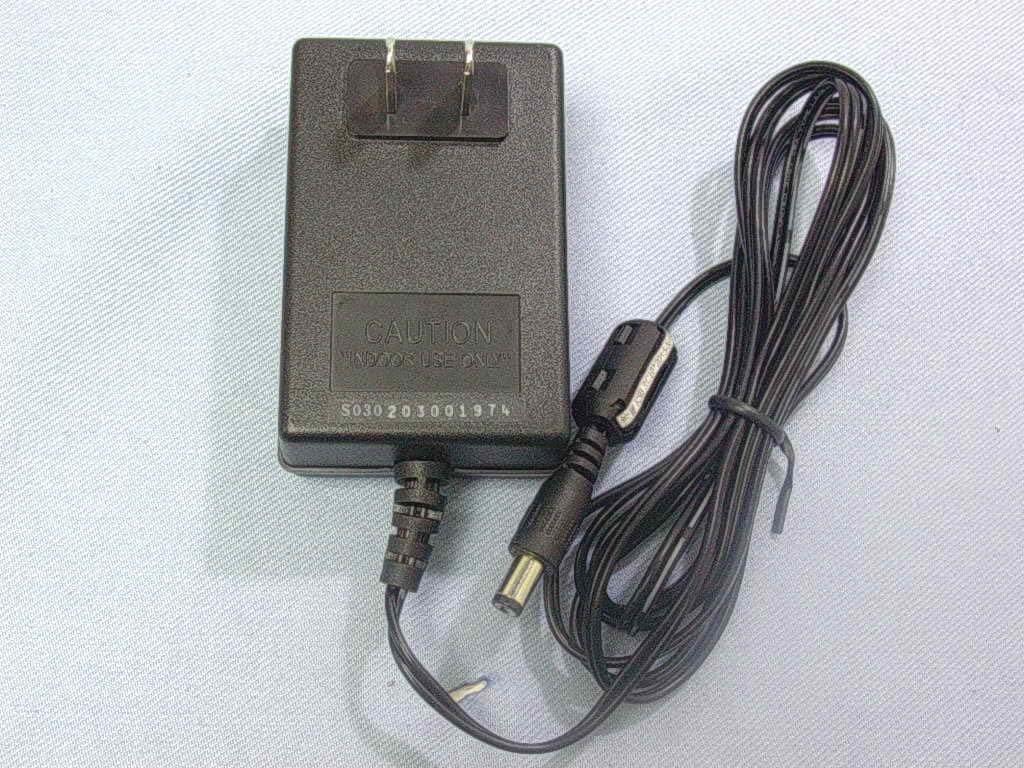
MAA-PW8540IM
Jun 30, 2004802.11 b/g Access Point Router
Equipment Class
DTS - Digital Transmission System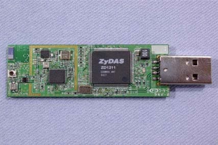
MAA-PW8630ZR
Jun 13, 2004802.11 b/g Wireless USB Dongle
Equipment Class
DTS - Digital Transmission System
MAA-PW8120AR
Jul 07, 2003WIRELESS LAN ACCESS POINT
Equipment Class
DTS - Digital Transmission System
MAAPW8120AR
Jul 02, 2003WIRELESS LAN ACCESS POINT
Equipment Class
DTS - Digital Transmission System
MAA8S273007
Jul 30, 1998JBP - Part 15 Class B Computing Device Peripheral
Equipment Class
JBP - Part 15 Class B Computing Device Peripheral