MAYDA58232450 MHz Mass Movement Sensor
Dynex Semiconductor Limited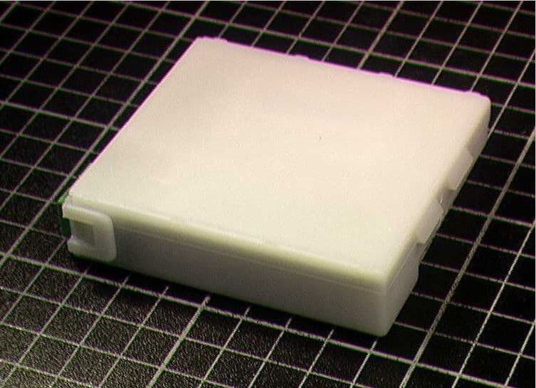
Click to zoom
Application Details
- Equipment Class
- FDS - Part 15 Field Disturbance Sensor
- Date of Grant
- Aug 22, 2002
- Application Purpose
- Original Equipment
- Date of Application
- Aug 22, 2002
- Equipment Note
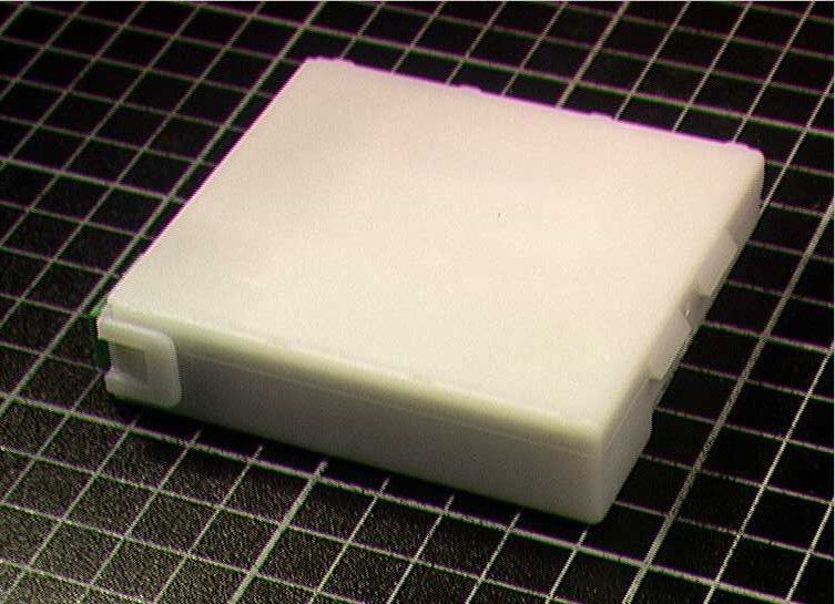
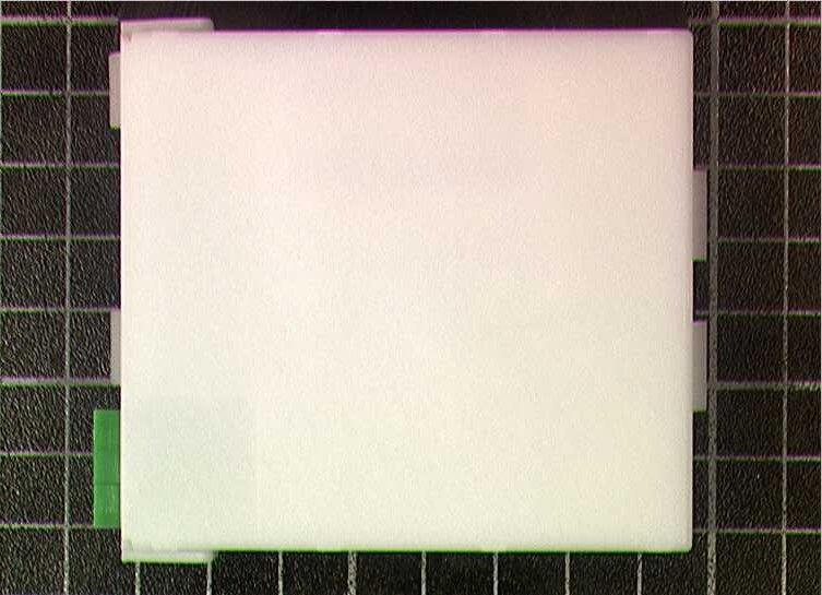
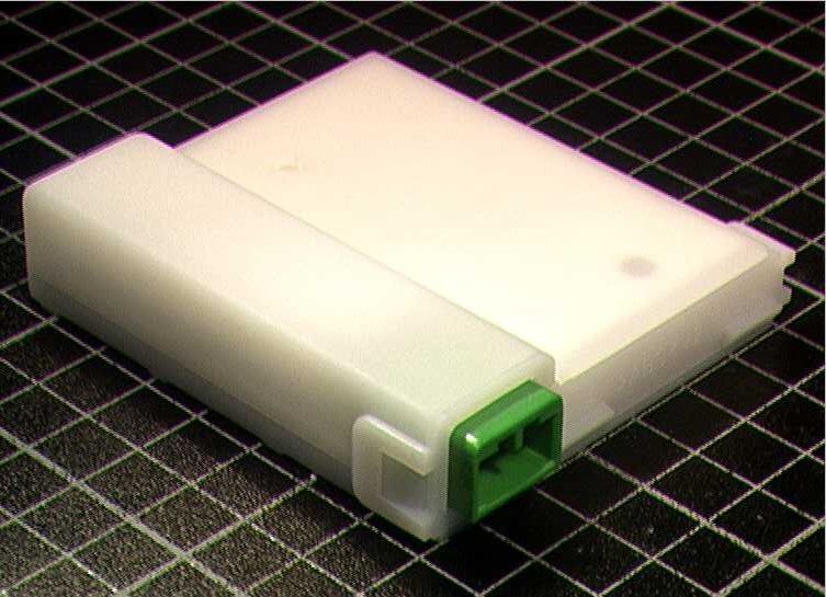
- 2450 MHz Mass Movement Sensor
- Frequency Range
- 2446.00000000 - 2454.00000000
- Company
- Dynex Semiconductor Limited
- Country
- United Kingdom
Documents & Files
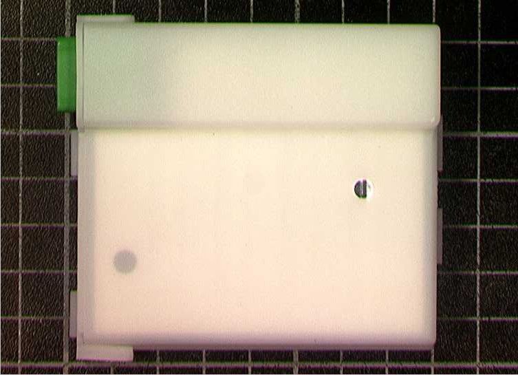
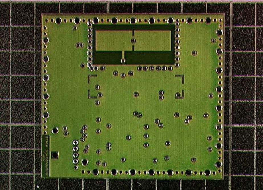
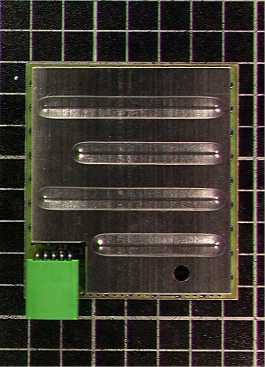
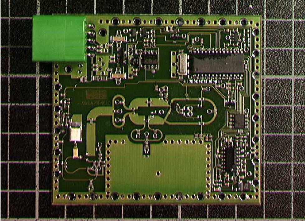
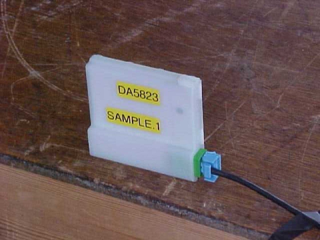
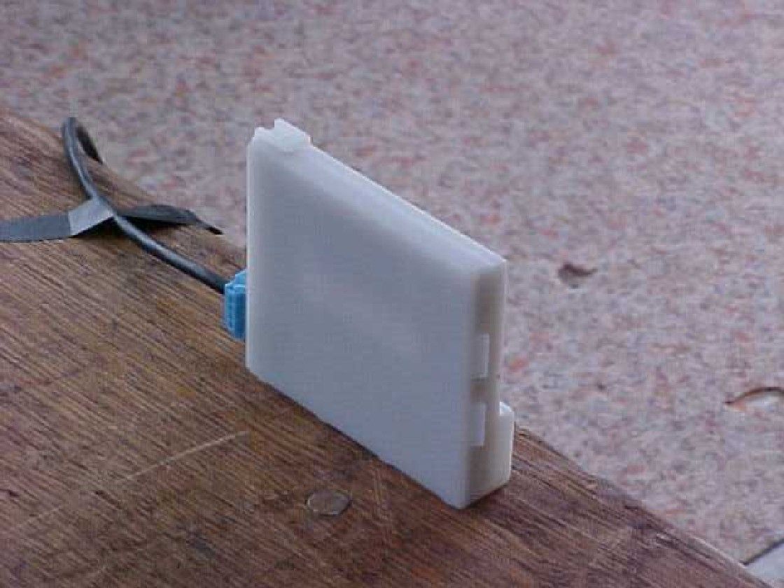
Document Text
Text extracted from the exhibit documents filed with the FCC. Open a document above to read the original.
Users Manual
1/5 AN5373 Application Note AN5373 Mass Movement Vehicle Alarm Sensors Application Note AN5373-1.1 July 2000 Filter Every Event Comparator Output Comparator Amplifiers Oscillator Antennae Detector Temp. comp. ASIC Voltage Regulator Timing Function Protection Circuitry Fig. 1: MMS schematic 1.INTRODUCTION The Dynex Semiconductor Mass Movement Sensor (MMS) is a volumetric microwave Doppler radar sensor that operates at 2.45 GHz in the ISM band. The MMS is ideal for use in vehicle security systems and is compatible with existing alarm systems that incorporate a volumetric sensor input. The sensor is supplied as a fully assembled and tested unit, designed for housing in a customer’s own case following the Dynex Semiconductor guidelines. The sensor is suitable for use in all classes of vehicles including: lSaloons, Touring and SUV’s lCabriolet, Convertibles and Roadsters lLight and Heavy Commercial Vehicles The MMS detection range can be adjusted so that the microwave beam coverage is confined within the desired area of the vehicle. Microwave radar technology offers benefits over competing technologies, lExtremely low false alarm level lImmunity to climatic change lSingle sensor - Easy Installation lSensor can be hidden behind trim lHigh level of EMC immunity lProtection with windows and load space doors open 2. FUNCTIONALITY The sensor utilises the Doppler effect principle. A frequency stabilised transistor oscillator is used to generate a RF signal at 2.450GHz. This signal is transmitted via a planar patch antenna structure embodied into the design of the printed circuit board to produce a free space RF beam pattern approximating to a hemi- spherical ellipse. The RF beam shape within a vehicle will be modified due to internal reflections and resonance’s particular to the vehicle and its internal structure. The size and material of a target determines the amplitude of the received Doppler signal, the velocity of a target determines the Doppler frequency. Reflections within the vehicle from stationary objects such as the seats and steering column produce no Doppler shift and therefore do not trigger the sensor. However, movement within the defined sensor range will be detected and generate an alarm event. 2/5 AN5373 Application Note Interior detection Steering Wheel: Good Rear Parcel Shelf: Poor Front Seats:Good Side Doors:Good Rear Seats :Weak Door Pockets:Good Radio:Good Glovebox:Good Interior detection Steering Wheel: Weak Rear Parcel Shelf: Weak Front Seats:Good Side Doors:Good Rear Seats :Good Door Pockets:Poor Radio:Good Glovebox:Weak Fig. 2: Centre roof mounted Fig. 3: Front roof mounted The Doppler frequency (D f ) generated by a moving target within the sensor detection area is equal to, where fo is the signal transmitted frequency, v is the velocity of the target and c is the velocity of light. The frequency shifted signal is received by the same antenna structure and is mixed with the transmitted signal to generate the base band Doppler signal. The low frequency, low amplitude Doppler signal is then processed by a custom designed mixed signal ASIC. A block schematic of the MMS alarm sensor is shown in Figure 1. The ASIC first amplifies and filters the Doppler signal to remove noise. The analogue signal is then processed by an ‘every event’ window comparator which generates a digital output for every signal that exceeds the comparator thresholds. The ‘every event’ digital output can be fed to an external alarm control unit for further software signal processing to determine if the detected targets constitute a real alarm event. If the alarm control unit does not have a software algorithm capability then the MMS can integrate the ‘every event’ outputs to generate a main alarm event output. 3. IN CAR PERFORMANCE The performance specification of a volumetric sensor based system is primarily determined by balancing the three main requirements, lZero False Alarms lFull Interior coverage lGuaranteed Theft detection No known system can meet these three needs simultaneously, but a balance of performance parameters can be tempered to any one customer’s personal preference. To understand the trade-off between system performance parameters it is useful to define certain terminology. False Alarms A false alarm is an action or situation that does not threaten the welfare of the interior of the vehicle. It is convenient however to categorise ‘false alarms’ into two categories: Accidental and Intentional. Accidental False Alarms: This may refer to such occurrences commonly experienced with ultrasonic sensors, such as; climatic changes, strong winds buffeting the vehicle, shock waves from aircraft take-off, insects within the car, EMC. c vf D o f 2 = 3/5 AN5373 Application Note Interior detection Steering Wheel: Weak Rear Parcel Shelf: Poor Front Seats:Good Side Doors:Good Rear Seats :Poor Door Pockets:Good Radio:Good Glovebox:Good Fig. 4: Front centre console mounted Interior detection Steering Wheel: Weak Rear Parcel Shelf: Poor Front Seats:Weak Side Doors:Good Rear Seats :Poor Door Pockets:Weak Radio:Good Glovebox:Good Fig.5: Front floor mounted Intentional False Alarms: An example of an intentional false alarm is by rocking the vehicle as to cause the interior contents to move and generate an alarm event. An intentional false alarm is characterised by the intent of someone to trigger the alarm to cause nuisance or to deactivate the volumetric sensor. Ultimately any volumetric sensor can be triggered if the intent is strong enough. The primary objective is to make the security system immune to simple intentional false alarm events. Interior Coverage The interior coverage of the sensor is the internal volume of the vehicle within which it is possible to reliably detect a thief attempting to steal the vehicle itself or the major valuable contents. Definition of the interior coverage is partially dependent upon the alarm system philosophy. The main parameters that interior alarm sensors would like …
Text truncated - open the document above for the full version.
Block Diagram
3MS Block Diagram Sheet 1 of 1
Cover Letter(s)
22 August 2002 Telecommunication Certification Body Radio Frequency Investigation Ltd. Ewhurst Park Ramsdell Basingstoke Hampshire RG26 5RQ England Subject: Certification Application FCC ID: MAYDA5823 It is requested that the following information is to be held co nfidential on behalf of Dynex Semiconductor Limited. FCC Rules Part 0.459 refers. ExhibitNumber of filesNumber of pages per file A0499-Board-Layout 11 A0499-bom14 A0499-circuit-diagram12 This information is highly commercially sensitive, in order to prevent competition copying this leading edge design. In order to prevent unauthorised disclosure, the information co ntained in the above listed files is only ever supplied by Dynex o n a need to know basis and then only o nce a No ne Disclosure Agreement (NDA) is in place between Dynex and the intended recipient. Such information is not available to the general public and sho uld be co nsidered confidential from now onwards. Yo urs si ncer ely Paul Carter
ID Label/Location Info
SENSOR PRODUCTS PROPOSED LABELLING - DA5823- 031 and DA5823-032 FIGURE 1: Proposed Label NOTES: 1. Figure 1 is a scanned image and is for indication purposes only. 2. The poposed labelling for the DA5823-031 variant is identical to Figure 1 with 032 replaced by 031. 3. Information labelled with ‘X’ or ‘Y’ will be replaced by alphanumeric characters as and when they become available. 4. The label will be durably applied to the product in accordance with the relevant Final Asse mbly drawing. 40 mm 60 mm
Operational Description
Sheet 1 of 1
Test Report
TEST REPORT FROM RADIO FREQUENCY INVESTIGATION LTD. Test Of: Dynex Semiconductors Ltd DA5823 Transceiver To: FCC Part 15 Subpart C (Intentional Radiators) Section 15.245 Test Report Serial No: RFI/MPTB1/RP43607JD01A This Test Report Is Issued Under The Authority Of Richard Jacklin, Operations Director: Checked By: pp Tested By:Release Version No: PDF01 Issue Date: 22 August 2002Test Date: 04 July 2002 This report is issued in Adobe Acrobat portable document format (PDF). It is only a valid copy of the report if it is being viewed in PDF format with the following security options not allowed: Changing the document, Selecting text and graphics, Adding or changing notes and form fields. Furthermore, the date of creation must match the issue date stated above. This report may be copied in full. The results in this report apply only to the sample(s) tested. RADIO FREQUENCY INVESTIGATION LTD.TEST REPORT S.No: RFI/MPTB1/RP43607JD01A EMC DepartmentPage 2 of 22 Issue Date: 22 August 2002 Test Of:Dynex Semiconductors Ltd DA5823 Transceiver To:FCC Part 15 Subpart C (Intentional Radiators) Section 15.245 This page has been left intentionally blank. RADIO FREQUENCY INVESTIGATION LTD.TEST REPORT S.No: RFI/MPTB1/RP43607JD01A EMC DepartmentPage 3 of 22 Issue Date: 22 August 2002 Test Of:Dynex Semiconductors Ltd DA5823 Transceiver To:FCC Part 15 Subpart C (Intentional Radiators) Section 15.245 Table of Contents 1. Client Information...................................................................................................... 4 2. Equipment Under Test (EUT) .................................................................................... 5 3. Test Specification, Methods And Procedures ......................................................... 7 4. Deviations From The Test Specification .................................................................. 8 5. Operation Of The EUT During Testing ..................................................................... 9 6. Summary Of Test Results ....................................................................................... 10 7. Measurements, Examinations And Derived Results ............................................. 11 8. Measurement Uncertainty....................................................................................... 15 Appendix 1. Test Equipment Used.............................................................................. 16 Appendix 2. Measurement Methods............................................................................ 17 Appendix 3. Test Configuration Drawings.................................................................. 19 RADIO FREQUENCY INVESTIGATION LTD.TEST REPORT S.No: RFI/MPTB1/RP43607JD01A EMC DepartmentPage 4 of 22 Issue Date: 22 August 2002 Test Of:Dynex Semiconductors Ltd DA5823 Transceiver To:FCC Part 15 Subpart C (Intentional Radiators) Section 15.245 1. Client Information Company Name: Dynex Semiconductor Ltd Address: Doddington Road Lincoln Lincolnshire LN6 3LF Contact Name: Mr G Dobson RADIO FREQUENCY INVESTIGATION LTD.TEST REPORT S.No: RFI/MPTB1/RP43607JD01A EMC DepartmentPage 5 of 22 Issue Date: 22 August 2002 Test Of:Dynex Semiconductors Ltd DA5823 Transceiver To:FCC Part 15 Subpart C (Intentional Radiators) Section 15.245 2. Equipment Under Test (EUT) The following information (with the exception of the Date of Receipt) has been supplied by the client: 2.1. Identification Of Equipment Under Test (EUT) Brand Name: Dynex Semiconductor Model Name or Number: DA5823 Unique Type Identification: 032 Serial Number: DA5823-032-022612-00190 Country of Manufacture: United Kingdom FCC ID Number: MAYDA5823 Date of Receipt: 04 July 2002 2.2. Description Of EUT The equipment under test is a Dynex Semiconductor Movement Sensor, it is a volumetric microwave Doppler radar sensor that operates at 2.45 GHz in the ISM band. The unit is intended for security/alarm applications such as the protection of the interior of a vehicle against any unauthorised entry or other domestic security alarm systems. The DA5823 is an OEM product and is designed for automotive applications. The device consists of an autodyne radar, based on a ceramic resonator stabilised transistor oscillator and balanced mixer, coupled to a patch antenna. The Doppler output from the mixer is fed to a microcontroller for signal processing, where an alarm output is generated when unusual movement has been detected. An alarm condition is signalled by the output of a single logic bit of approximately 1 second duration. The microcontroller also controls duty cycling of the RF power and the setting of the analogue gain of the unit. The sensors analogue gain is determined by Dynex Semiconductor although the sensors’ detection range can be varied electronically for different applications so long as the control unit supports the programming protocol. RADIO FREQUENCY INVESTIGATION LTD.TEST REPORT S.No: RFI/MPTB1/RP43607JD01A EMC DepartmentPage 6 of 22 Issue Date: 22 August 2002 Test Of:Dynex Semiconductors Ltd DA5823 Transceiver To:FCC Part 15 Subpart C (Intentional Radiators) Section 15.245 2.3. Modifications Incorporated In EUT The EUT has not been modified from the Model Name or Unique Type Identification number stated above. 2.4. Additional Information Related To Testing Power Supply Requirement: DC Supply of 12 Volts Intended Operating Environment: Vehicle Interior Weight: 0.06 kg Dimensions: 82.1 x 71.8 x 18.6 mm Interface Ports: 5 Pin Socket incorporating +12v, Ground and programming pins. 2.5. Support Equipment No support equipment was used to exercise the EUT during testing. RADIO FREQUENCY INVESTIGATION LTD.TEST REPORT S.No: RFI/MPTB1/RP43607JD01A EMC DepartmentPage 7 of 22 Issue Date: 22 August 2002 Test Of:Dynex Semiconductors Ltd DA5823 Transceiver To:FCC Part 15 Subpart C (Intentional Radiators) Section 15.245 3. Test Specification, Methods And Procedures 3.1. Test Specification Reference: FCC Part 15: 2001 Subpart C (Intentional Radia…
Text truncated - open the document above for the full version.
Contact Information
Applicant
Graeme Dobson(Senior Product Engineer)
Technical Contact
Dynex Semiconducter LtdMervyn K Hobden
[email protected]+441522500500
Doddington Road · Lincoln · United Kingdom
Non-Technical Contact
Dynex Semiconducter LtdJim W Townsend
[email protected]+441522500500
Test Firm
RFI Global Services Ltd.Allan Hume
Technical Specifications
| # | Rule Parts | Frequency Range | Power Output |
|---|---|---|---|
| 1 | 15.245 | 2.45 GHz - 2.45 GHz | 1.00 mW |
Other Applications from Dynex Semiconductor Limited
MAYDA58233
Apr 28, 20032450 MHz Mass Movement Sensor
Equipment Class
FDS - Part 15 Field Disturbance SensorMAYDA5815
Sep 26, 1995Car Security Sensor
Equipment Class
FDS - Part 15 Field Disturbance Sensor