MCL60740EUW802.11 b/g PCMCIA Module
HON HAI Precision Ind. Co., Ltd.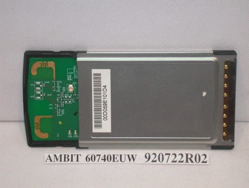
Click to zoom
Application Details
- Equipment Class
- DTS - Digital Transmission System
- Date of Grant
- Aug 07, 2003
- Application Purpose
- Original Equipment
- Date of Application
- Aug 03, 2003
- Equipment Note
- 802.11 b/g PCMCIA Module
- Frequency Range
- 2412.00000000 - 2462.00000000
- Country
- Taiwan
Documents & Files
Document Text
Text extracted from the exhibit documents filed with the FCC. Open a document above to read the original.
Users Manual
Wireless PCMCIA Card User Manual Chapter 1 About the Wireless PCMCIA Card........................... 3 1-1 Features .......................................................................... 3 1-2 Applications ................................................................... 3 1-3 Product Kit ..................................................................... 4 Chapter 2 Network Configuring and Planning .......................... 5 2-1 Network Topology.......................................................... 5 2-2 Roaming ......................................................................... 7 Chapter 3 Installation ................................................................ 8 3-1 System Requirements ..................................................... 8 3-2 Inserting the Wireless Card ............................................ 8 3-3 Installation and Uninstall Process .................................. 8 Chapter 4 Wireless Utility and Configuration ......................... 15 4-1 Windows 98/ME/2000 Wireless Utility ....................... 15 4-2 Windows XP Wireless Utility....................................... 20 Appendix A Troubleshooting .................................................. 27 Appendix B Glossary............................................................... 28 Appendix C Specifications for Wireless Card ......................... 29 Chapter 1About the Wireless PCMCIA Card This IEEE 802.11g Wireless PCMCIA Card is compatible with notebook computer Type II or Type III PCMCIA slot. As a Plug-and-Play device, Windows 98/2000/ME/XP will automatically recognize the wireless PCMCIA Card and initiate the installation process. Upon successful installation, the wireless PCMCIA Card will communicate seamlessly with other IEEE 802.11g wireless products. 1-1 Features 1. Supports up to 54 Mbps data rate. 2. Supports point-to-point and point-to-multipoint access provides increased flexibility. 3. Seamless connectivity to wired Ethernet and PC network LAN’s offers quick, trouble-free integration with existing networks. 4. Direct Sequence Spread Spectrum (DSSS) technology provides secure wireless connection. 5. Wireless connections eliminate the hassle and cost of cabling. 6. Supports a wide range of LAN (Local Area Network) Network Operating Systems (NOS) including Windows 98/2000/ ME/XP 7. Easy Plug and Play installation. 8. Omni - directional antenna provides wide range of reception. 9. Greater flexibility to locate or move networked PC’s 10. PCMCIA will support a ACTIVITY LED for feedback to the user on the current WLAN activity state. The signaling shall reflect the activity as follows: 1-2 Applications This wireless PCMCIA cards offer a fast, reliable, cost-effective solution for wireless client access to the network. Refer below for examples : z Remote access to corporate network information z E-mail, file transfer and terminal emulation z Difficult-to-wire environments z Historic or older buildings without Ethernet wiring. z Buildings with asbestos insulation z Open areas where wiring is difficult to employ z Re-layout frequently environments z Retailers, manufacturers or other organizations that frequently rearrange the workplace or relocate z Temporary LANs for special projects or peak time usage z Trade shows, exhibitions and construction sites that employ temporary networks. z Retailers, airline and shipping companies that need additional workstations for a peak period and auditors that require workgroups at customer sites. z Access to database for mobile workers z Medical, technical and retail specialists that require roaming access to a database or other network resources. z SOHO (Small Office and Home Office) users z Perfect for users that need a small, easy-to-install network that deploys rapidly. 1-3 Product Kit The wireless PCMCIA card includes the following items. Ensure that the items in the following list have been included. If any of the listed items are missing, please contact your local dealer. z One wireless PCMCIA Type II PCMCIA card z One Compact Disk. The CD include 98/2000/ME/XP driver, utility and user manual Chapter 2Network Configuring and Planning The wireless PCMCIA card supports legacy Ethernet LAN network configuration options as defined by the IEEE 802.11g. The wireless PCMCIA card can be configured as: . Ad-Hoc mode for no Access Point wireless environment. . Infrastucture mode for wireless environment with Access Point. 2-1 Network Topology An Ad-Hoc wireless LAN is a group of computers. Each computer equipped with a wireless PCMCIA card that configure to same radio channel in order to communicate with others. Ad-Hoc wireless LAN configurations are appropriate for branch level departments or SOHO operations. A group of wireless users and an Access Point compose a Basic Service Set (BSS). Wireless clients can talk to any computer in both wired and wireless LAN network via the Access Point. 2-2 Roaming Infrastructure mode also supports roaming capabilities for mobile users. More than one BSS can be configured as an Extended Service Set (ESS). The continuous network allows users to roam freely within ESS. All wireless PCMCIA cards and Access Point within one ESS must be configured with the same ESSID in order to utilize roaming function. Properly Access Point positioning with a clear radio signal can greatly enhance wireless performance. Chapter 3Installation 3-1 System Requirements In order to install and use the wireless PCMCIA card in your notebook computer. Your notebook system must meet the following requirements: z A PCMCIA Type II Slot z Compact Disk Device 3-2 Inserting the Wireless Card 1. Locate an available Type II PCMCIA slot. 2. With the PCMCIA card pin connector facing the PCMCIA slot, you can easily insert the card into the slot. 3. After properly inserting the wireless card, you can continue with wireless driver and utility installation. 3-3 Installation and Uninstall Process Install AMBIT Wireless LAN (Windows 98/2K/ME…
Text truncated - open the document above for the full version.
Cover Letter(s)
[email protected] www.adt.com.tw ADVANCE DATA TECHNOLOGY CORPORATION FEDERAL COMMUNICATIONS COMMISSION DECLARATION OF CONFORMITY (DoC) FOR THE FOLLOWING EQUIPMENT: PRODUCT NAME: 802.11b/g PCMCIA module MODEL NO.: 60740EUW TRADE NAME: AMBIT IS HEREWITH CONFIRMED AND FOUND TO COMPLY WITH THE REQUIREMENTS OF CFR 47 PART 15 REGULATION. THE RESULTS OF ELECTROMAGNETIC EMISSION EVALUATION ARE SHOWN IN THE REPORT NO.: RF920722R02 THIS DEVICE COMPLIES WITH PART 15 OF THE FCC RULES. OPERATION IS SUBJECT TO THE FOLLOWING TWO CONDITIONS: (1) THIS DEVICE MAY NOT CAUSE HARMFUL INTERFERENCE AND, (2) THIS DEVICE MUST ACCEPT ANY INTERFERENCE RECEIVED, INCLUDING INTERFERENCE THAT MAY CAUSE UNDESIRED OPERATION. THE FOLLOWING LOCAL MANUFACTURER/IMPORTER IS RESPONSIBLE FOR THIS DECLARATION: ManufacturerUSA Local Representative Company name: AMBIT Microsytems Corporation To Be Determined. Address: 4-1,Ming-Sheng ST., Tu-Cheng Industrial Area, Tu-Cheng City, Taipei,Taiwan R.O.C. Contact Person: Rio Chen Title: Supervisor Te l / F a x : +886 3-5784975#331 +886 2-22676512
Cover Letter(s)
FCC ID: MCL60740EUW ADT No. 920722R02 Limited Modular Approval Request Letter Advance Data Technology Jul. 30, 2003 Dear Application Examiner, AMBIT Microsystems Corporation’s 802.11b/g PCMCIA module, FCC ID: MCL60740EUW, would like to have your authorization as a limited modular approval specific to the mobile device such as AP, Router, Cable Modem, mobile device. The requirements of Public Notice DA00-1407 have been met and shown on the following statements. 1. “The modular transmitter must have its own RF shielding.”: The radio portion of this module has been shielded, please see exhibition External Photo. 2. “The modular transmitter must have buffered modulation/data inputs.” The EUT has buffered data inputs, it is integrated in chip BCM4306. 3. “The modular transmitter must have its own power supply regulation.” The chips RF converter which will influence the frequency radiation, have to be 2.5V DC powered. The PCMCIA interface provides 3.3VDC, so there are regulators in front of these chips, the part number of this regulator is NI_MIC5209. 4. “The modular transmitter must comply with the antenna requirements of section 15.203 and 15.204(C).” The EUT meets the FCC antenna requirements. The spurious emission, unique antenna connector and photo of antennas are shown in the test report. 5. “The modular transmitter must be labeled with its own FCC ID number.” Please see exhibition Label Sample for the FCC ID of this module, so the EUT was tested in the full system configuration. Please see section Photographs of Test Configuration in the test report. 6. “The modular transmitter must be labeled with its own FCC ID number.” Please see exhibition Label Sample for the FCC ID of this module. And also in the exhibition Users Manual, there are instructions give to the OEM on how to label the end product. FCC ID: MCL60740EUW ADT No. 920722R02 7. “The modular transmitter must comply with any specific rule or operating requirements applicable to the transmitter and the manufacturer must provide adequate instructions along with the module to explain any such requirements.” The EUT is compliant with all applicable FCC rules. Detail instructions for maintaining compliance are given in the Users Manual. 8. “The modular transmitter must comply with any applicable RF exposure requirements.” The EUT is compliant with all applicable RF exposure requirements. RF Exposure is addressed in the RF exposure exhibition. Please contact me if you have any further questions. Thanks for your attention. Best Regards, Eric Lin Manager of Hsinchu Certification Service Div. Advance Data Technology
Cover Letter(s)
American Telecommunications Certification Body Inc. 6731 Whittier Ave, McLean, VA 22101 August 4, 2003 RE: AMBIT Microsystems Corporation FCC ID: MCL60740EUW I have a few comments on this Application. 1.) This device has channels for the US, Japan and ETSI. Could you please explain how you insure that the US user cannot access the extra channels. Thank you, Douglas E. Noble Examining Engineer mailto: [email protected] The items indicated above must be submitted before processing can continue on the above referenced application. Failure to provide the requested information may result in application termination. Correspondence should be considered part of the permanent submission and may be viewed from the Internet after a Grant of Equipment Authorization is issued. Please do not respond to this correspondence using the email reply button. In order for your response to be processed expeditiously, you must submit your documents through the AmericanTCB.com website. Also, please note that partial responses increase processing time and should not be submitted. Any questions about the content of this correspondence should be directed to the sender.
Cover Letter(s)
American Telecommunications Certification Body Inc. 6731 Whittier Ave, McLean, VA 22101 August 4, 2003 RE: AMBIT Microsystems Corporation FCC ID: MCL60740EUW I have a few comments on this Application. 1.) This device has channels for the US, Japan and ETSI. Could you please explain how you insure that the US user cannot access the extra channels. Thank you, Douglas E. Noble Examining Engineer mailto: [email protected] The items indicated above must be submitted before processing can continue on the above referenced application. Failure to provide the requested information may result in application termination. Correspondence should be considered part of the permanent submission and may be viewed from the Internet after a Grant of Equipment Authorization is issued. Please do not respond to this correspondence using the email reply button. In order for your response to be processed expeditiously, you must submit your documents through the AmericanTCB.com website. Also, please note that partial responses increase processing time and should not be submitted. Any questions about the content of this correspondence should be directed to the sender.
External Photos
Page 1 CONSTRUCTION PHOTOS OF EUT Page 2 Page 3
ID Label/Location Info
FCC ID : MCL60740EUW Ambit 60740EUW. The above is for USA Label drawing.
Internal Photos
Page 1 CONSTRUCTION PHOTOS OF EUT Page 2 Page 3 Page 4
Operational Description
FCC ID: MCL60740EUW ADT No. 920722R02 Operational Description This device is an 802.11b/g PCMCIA module which operates in the 2.4GHz band, the maximum data rate could be up to 54Mbps which OFDM technique will be applied. If the signal to noise radio is too poor which could not support 54Mbps, the 11Mbps data rate with CCK technique will be applied. The transmitter of the EUT (802.11b/g PCMCIA module) is powered by from host equipment. The antenna type used in this product is Dipole Antenna with HRS connector. The other instruction, please have a look at the users manual.
RF Exposure Info
FCC ID: MCL60740EUW ADT No.: 920722R02 RF EXPOSURE REPORT REPORT NO.: RF920722R02 MODEL NO.: 60740EUW ACCORDING: FCC Guidelines for Human Exposure IEEE C95.1 APPLICANT: AMBIT Microsystems Corporation ADDRESS: 5F-1,5 Hsin-An Road Hsinchu, Science-Based Industrial Park Taiwan, R.O.C. ISSUED BY: Advance Data Technology Corporation LAB LOCATION: No. 81-1, Lu Liao Keng, 9 Ling, Wu Lung Tsuen, Chiung Lin Hsiang, Hsin Chu Hsien, Taiwan, R.O.C. Lab Code: 200376-0 FCC ID: MCL60740EUW ADT No.: 920722R02 RF Exposure Measurement 1. Introduction In this document, we try to prove the safety of radiation harmfulness to the human body for our product. The limit for Maximum Permissible Exposure (MPE) specified in FCC 1.1310 is followed. The Gain of the antenna used in this product is measured in a Fully Anechoic Chamber (FAC) calibrated for antenna measurement in ADT, and also the maximum total power input to the antenna is measured. Through the Friis transmission formula and the maximum gain of the antenna, we can calculate the distance, away from the product, where the limit of MPE is reached. Although the Friis transmission formula is a far field assumption, the calculated result of that is an over-prediction for near field power density. We will take that as the worst case to specify the safety range. 2. RF Exposure Limit According to FCC 1.1310: The criteria listed in the following table shall be used to evaluate the environmental impact of human exposure to radio-frequency (RF) radiation as specified in 1.1307(b) LIMITS FOR MAXIMUM PERMISSIBLE EXPOSURE (MPE) Frequency Range (MHz) Electric Field Strength (V/m) Magnetic Field Strength (A/m) Power Density (mW/cm 2 ) Average Time (minutes) (A)Limits For Occupational / Control Exposures 300-1500......F/3006 1500-100,000......56 (B)Limits For General Population / Uncontrolled Exposure 300-1500......F/15006 1500-100,000......1.030 F = Frequency in MHz FCC ID: MCL60740EUW ADT No.: 920722R02 3. Friis Formula Friis transmission formula : Pd = (Pout*G) / (4*pi*r 2 ) where Pd = power density in mW/cm 2 Pout = output power to antenna in mW G = gain of antenna in linear scale Pi = 3.1416 R = distance between observation point and center of the radiator in cm Pd is the limit of MPE, 1 mW/cm 2 . If we know the maximum Gain of the antenna and the total power input to the antenna, through the calculation, we will know the MPE value at distance 20cm. Ref. : David K. Cheng, Field and Wave Electromagnetics, Second Edition, Page 640, Eq. (11-133). 4 EUT Operating condition The software provided by Manufacturer enabled the EUT to transmit and receive data at lowest, middle and highest channel individually. 5. Classification The antenna of this product, under normal use condition, is at least 20cm away from the body of the user. Warning statement to the user for keeping at least 20cm or more separation distance with the antenna should be included in users manual. So, this device is classified as Mobile Device. FCC ID: MCL60740EUW ADT No.: 920722R02 6 Test Results 6.1 Antenna Gain The maximum Gain measured in Fully Anechoic Chamber is 4Bi or 2.51 (numeric). 6.2 Output Power Into Antenna & RF Exposure value at distance 20cm: For DSSS Channel Channel Frequency (MHz) Output Power to Antenna (mW) Power Density (mW/cm 2 ) Limit of Power Density (mW/cm 2 ) 1241241.6810.0036961.0 6243740.9260.0036451.0 11246240.6440.0034491.0 For OFDM Channel Channel Frequency (MHz) Output Power to Antenna (mW) Power Density (mW/cm 2 ) Limit of Power Density (mW/cm 2 ) 1241241.5910.0044851.0 6243740.7380.0032941.0 11246240.0870.0027841.0
Test Report
FCC ID: MCL60740EUW Report No.: RF920722R0241Issed: Jul.30, 2003 ADT No.: 920722R02 CH1 FCC ID: MCL60740EUW Report No.: RF920722R0242Issed: Jul.30, 2003 ADT No.: 920722R02 CH6 FCC ID: MCL60740EUW Report No.: RF920722R0243Issed: Jul.30, 2003 ADT No.: 920722R02 CH11 FCC ID: MCL60740EUW Report No.: RF920722R0244Issed: Jul.30, 2003 ADT No.: 920722R02 4.5.7 TEST RESULTS-OFDM EUT802.11b/g PCMCIA module MODEL60740EUW ENVIRONMENTAL CONDITIONS 21 deg. C, 58 %RH, 965 hPa INPUT POWER (SYSTEM) 120Vac, 60 Hz TESTED BY Eric Lee CHANNEL NUMBER CHANNEL FREQUENCY (MHz ) RF POWER LEVEL IN 3 KHz BW (dBm) MAXIMUM LIMIT (dBm) PASS/FAIL 124120.258PASS 62437-0.098PASS 112462-0.998PASS FCC ID: MCL60740EUW Report No.: RF920722R0245Issed: Jul.30, 2003 ADT No.: 920722R02 CH1 FCC ID: MCL60740EUW Report No.: RF920722R0246Issed: Jul.30, 2003 ADT No.: 920722R02 CH6 FCC ID: MCL60740EUW Report No.: RF920722R0247Issed: Jul.30, 2003 ADT No.: 920722R02 CH11 FCC ID: MCL60740EUW Report No.: RF920722R0248Issed: Jul.30, 2003 ADT No.: 920722R02 4.6 BAND EDGES MEASUREMENT 4.6.1 LIMITS OF BAND EDGES MEASUREMENT Below –20dB of the highest emission level of operating band (in 100KHz Resolution Bandwidth). 4.6.2 TEST INSTRUMENTS Description & ManufacturerModel No.Serial No.Calibrated Until R&S SPECTRUM ANALYZERFSP1093.4495.30Dec. 19, 2003 NOTE: 1.The measurement uncertainty is less than +/- 2.6dB, which is calculated as per the NAMAS document NIS81. 2.The calibration interval of the above test instruments is 12 months and the calibrations are traceable to NML/ROC and NIST/USA. 4.6.3 TEST PROCEDURE The transmitter output was connected to the spectrum analyzer via a low lose cable. Set both RBW and VBW of spectrum analyzer to 100 kHz with suitable frequency span including 100 kHz bandwidth from band edge. The band edges was measured and recorded. 4.6.4 EUT OPERATING CONDITION Same as Item 4.3.5 FCC ID: MCL60740EUW Report No.: RF920722R0249Issed: Jul.30, 2003 ADT No.: 920722R02 4.6.5 TEST RESULTS - DSSS The spectrum plots are attached on the following 2 pages. D1 line indicates the highest level, D2 line indicates the 20dB offset below D1. It shows compliance with the requirement in part 15.247(C). NOTE (1): The band edge emission plot on the following first page shows 53.84dB delta between carrier maximum power and local maximum emission in restrict band (2.3900GHz). The emission of carrier strength list in the test result of channel 1 at the item 4.2.7 is 101.1dBuV/m, so the maximum field strength in restrict band is 101.1-53.84=47.26dBuV/m which is under 54 dBuV/m limit. NOTE (2): The band edge emission plot on the following second page shows 54.77dB delta between carrier maximum power and local maximum emission in restrict band (2.4852GHz). The emission of carrier strength list in the test result of channel 11 at the item 4.2.7 is 100.7dBuV/m, so the maximum field strength in restrict band is 100.7-54.77=45.93dBuV/m which is under 54 dBuV/m limit. FCC ID: MCL60740EUW Report No.: RF920722R0250Issed: Jul.30, 2003 ADT No.: 920722R02 FCC ID: MCL60740EUW Report No.: RF920722R0251Issed: Jul.30, 2003 ADT No.: 920722R02 FCC ID: MCL60740EUW Report No.: RF920722R0252Issed: Jul.30, 2003 ADT No.: 920722R02 4.6.6 TEST RESULTS-OFDM The spectrum plots are attached on the following 2 pages. D1 line indicates the highest level, D2 line indicates the 20dB offset below D1. It shows compliance with the requirement in part 15.247(C). NOTE (1): The band edge emission plot on the following first page shows 45.43dB delta between carrier maximum power and local maximum emission in restrict band (2.3896GHz). The emission of carrier strength list in the test result of channel 1 at the item 4.2.8 is 91.9dBuV/m, so the maximum field strength in restrict band is 91.9-45.43=46.47dBuV/m which is under 54 dBuV/m limit. NOTE (2): The band edge emission plot on the following second page shows 43.77dB delta between carrier maximum power and local maximum emission in restrict band (2.4836GHz). The emission of carrier strength list in the test result of channel 11 at the item 4.2.8 is 91.0dBuV/m, so the maximum field strength in restrict band is 91.0-43.77=47.23dBuV/m which is under 54 dBuV/m limit. FCC ID: MCL60740EUW Report No.: RF920722R0253Issed: Jul.30, 2003 ADT No.: 920722R02 FCC ID: MCL60740EUW Report No.: RF920722R0254Issed: Jul.30, 2003 ADT No.: 920722R02 FCC ID: MCL60740EUW Report No.: RF920722R0255Issed: Jul.30, 2003 ADT No.: 920722R02 4.7 ANTENNA REQUIREMENT 4.7.1 STANDARD APPLICABLE For intentional device, according to FCC 47 CFR Section 15.203, an intentional radiator shall be designed to ensure that no antenna other than that furnished by the responsible party shall be used with the device. And according to FCC 47 CFR Section 15.247 (b), if transmitting antennas of directional gain greater than 6dBi are used, the power shall be reduced by the amount in dB that the directional gain of the antenna exceeds 6dBi. 4.7.2 ANTENNA CONNECTED CONSTRUCTION The antenna type used in this product is Dipole Antenna with HRS connector. And the maximum Gain of this antenna is only 4dBi. FCC ID: MCL60740EUW Report No.: RF920722R0256Issed: Jul.30, 2003 ADT No.: 920722R02 5 PHOTOGRAPHS OF THE TEST CONFIGURATION CONDUCTED EMISSION TEST FCC ID: MCL60740EUW Report No.: RF920722R0257Issed: Jul.30, 2003 ADT No.: 920722R02 RADIATED EMISSION TEST FCC ID: MCL60740EUW Report No.: RF920722R0258Issed: Jul.30, 2003 ADT No.: 920722R02 FCC ID: MCL60740EUW Report No.: RF920722R0259Issed: Jul.30, 2003 ADT No.: 920722R02 6 INFORMATION ON THE TESTING LABORATORIES We, ADT Corp., were founded in 1988 to provide our best service in EMC and Safety consultation. Our laboratories are accredited and approved by the following approval agencies according to ISO/IEC 17025, Guide 25 or EN 45001: USA FCC, NVLAP, UL Germany TUV Rheinland Japan VCCI New Zealand MoC Norway NEMKO Canada INDUSTRY CANADA R.O.C. CNLA, BSMI Copies of accreditation certificates of our laboratories obtained from approval agencies…
Text truncated - open the document above for the full version.
Test Report
FCC ID: MCL60740EUW Report No.: RF920722R021Issed: Jul.30, 2003 ADT No.: 920722R02 FCC TEST REPORT REPORT NO.: RF920722R02 MODEL NO.: 60740EUW RECEIVED: Jul. 22, 2003 TESTED: Jul. 22 to 23, 2003 APPLICANT: AMBIT Microsystems Corporation ADDRESS: 5F-1,5 Hsin-An Road Hsinchu, Science-Based Industrial Park Taiwan, R.O.C. ISSUED BY: Advance Data Technology Corporation LAB LOCATION: No. 81-1, Lu Liao Keng, 9 Ling, Wu Lung Tsuen, Chiung Lin Hsiang, Hsin Chu Hsien, Taiwan, R.O.C. This test report consists of 59 pages in total. It may be duplicated completely for legal use with the approval of the applicant. It should not be reproduced except in full, without the written approval of our laboratory. The client should not use it to claim product endorsement by CNLA, NVLAP or any government agencies. The test results in the report only apply to the tested sample. Lab Code: 200376-0 FCC ID: MCL60740EUW Report No.: RF920722R022Issed: Jul.30, 2003 ADT No.: 920722R02 Table of Contents 1CERTIFICATION.......................................................................................................4 2SUMMARY OF TEST RESULTS...........................................................................5 3GENERAL INFORMATION.....................................................................................6 3.1GENERAL DESCRIPTION OF EUT......................................................................6 3.2DESCRIPTION OF TEST MODES........................................................................7 3.3GENERAL DESCRIPTION OF APPLIED STANDARDS...................................7 3.4DESCRIPTION OF SUPPORT UNITS.................................................................8 4TEST TYPES AND RESULTS................................................................................9 4.1CONDUCTED EMISSION MEASUREMENT......................................................9 4.1.1LIMITS OF CONDUCTED EMISSION MEASUREMENT..................................9 4.1.2TEST INSTRUMENTS.............................................................................................9 4.1.3TEST SETUP..........................................................................................................10 4.1.4EUT OPERATING CONDITIONS........................................................................11 4.1.5TEST RESULTS.....................................................................................................12 4.2Radiated Emission Measurement........................................................................14 4.2.1LIMITS OF RADIATED EMISSION MEASUREMENT.....................................14 4.2.2TEST INSTRUMENTS...........................................................................................15 4.2.3TEST PROCEDURES...........................................................................................16 4.2.4TEST SETUP..........................................................................................................17 4.2.5EUT OPERATING CONDITIONS........................................................................17 4.2.6TEST RESULTS.....................................................................................................18 4.2.7TEST RESULTS - DSSS.......................................................................................19 4.2.8TEST RESULTS -OFDM.......................................................................................22 4.36dB BANDWIDTH MEASUREMENT..................................................................25 4.3.1LIMITS OF 6dB BANDWIDTH MEASUREMENT.............................................25 4.3.2TEST INSTRUMENTS...........................................................................................25 4.3.3TEST PROCEDURE..............................................................................................26 4.3.4TEST SETUP..........................................................................................................26 4.3.5EUT OPERATING CONDITIONS........................................................................26 4.3.6TEST RESULTS-DSSS.........................................................................................27 4.3.7TEST RESULTS-OFDM........................................................................................31 4.4MAXIMUM PEAK OUTPUT POWER..................................................................35 4.4.1LIMITS OF MAXIMUM PEAK OUTPUT POWER MEASUREMENT.............35 FCC ID: MCL60740EUW Report No.: RF920722R023Issed: Jul.30, 2003 ADT No.: 920722R02 4.4.2TEST INSTRUMENTS...........................................................................................35 4.4.3TEST PROCEDURES...........................................................................................36 4.4.4TEST SETUP..........................................................................................................36 4.4.5EUT OPERATING CONDITIONS........................................................................36 4.4.6TEST RESULTS-DSSS.........................................................................................37 4.4.7TEST RESULTS-OFDM........................................................................................37 4.5POWER SPECTRAL DENSITY MEASUREMENT...........................................38 4.5.1LIMITS OF POWER SPECTRAL DENSITY MEASUREMENT......................38 4.5.2TEST INSTRUMENTS...........................................................................................38 4.5.3TEST PROCEDURE..............................................................................................39 4.5.4TEST SETUP..........................................................................................................39 4.5.5EUT OPERATING CONDITIONS........................................................................39 4.5.6TEST RESULTS-DSSS.........................................................................................40 4.5.7TEST RESULTS-OFDM................…
Text truncated - open the document above for the full version.
Test Setup Photos
FCC ID: MCL60740EUW Report No.: RF920722R0256Issed: Jul.30, 2003 ADT No.: 920722R02 5 PHOTOGRAPHS OF THE TEST CONFIGURATION CONDUCTED EMISSION TEST FCC ID: MCL60740EUW Report No.: RF920722R0257Issed: Jul.30, 2003 ADT No.: 920722R02 RADIATED EMISSION TEST FCC ID: MCL60740EUW Report No.: RF920722R0258Issed: Jul.30, 2003 ADT No.: 920722R02
Contact Information
Applicant
Mrs. Rio Chen(Compliance Deputy Manager)
Technical Contact
Advance Data Technology Corp.Eric Lin
[email protected]+886-3-593-5343
81-1 Luliaoken 9th Lin Wulung Tsuen · Hsinchu · Taiwan
Test Firm
Bureau Veritas CPS (H.K.) Ltd. Taoyuan BranchRichard Chen
Technical Specifications
| # | Rule Parts | Frequency Range | Power Output |
|---|---|---|---|
| 1 | 15C | 2.41 GHz - 2.46 GHz | 42.00 mW |
Other Applications from HON HAI Precision Ind. Co., Ltd.

MCLT77W968
Jun 03, 2021LTE M.2 Module
Equipment Class
CBE - Citizens Band End User Devices
MCLT77W968C9
Feb 13, 2020LTE M.2 Module
Equipment Class
PCB - PCS Licensed Transmitter
MCLADB1761WF
Jun 03, 2015IP Set-Top Box with Wi-Fi 11ac
Equipment Class
DTS - Digital Transmission System
MCLADB1761W
Jun 02, 2015IP Set-Top Box
Equipment Class
DTS - Digital Transmission System
MCLT77H566
Feb 16, 2015WiFi/BT Module
Equipment Class
DTS - Digital Transmission System