MCLAIRMPI350Wireless MiniPCI Card
HON HAI Precision Ind. Co., Ltd.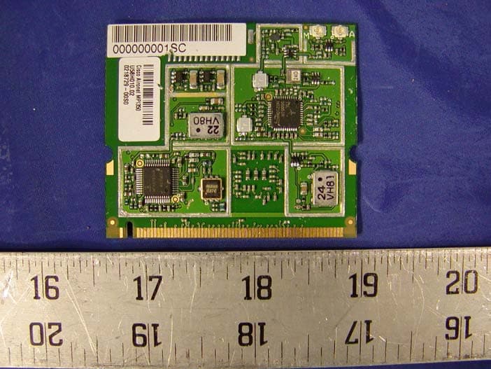
Click to zoom
Application Details
- Equipment Class
- DSS - Part 15 Spread Spectrum Transmitter
- Date of Grant
- Jul 23, 2002
- Application Purpose
- Original Equipment
- Date of Application
- Jul 23, 2002
- Equipment Note
- Wireless MiniPCI Card
- Frequency Range
- 2412.00000000 - 2472.00000000
- Country
- Taiwan
Documents & Files
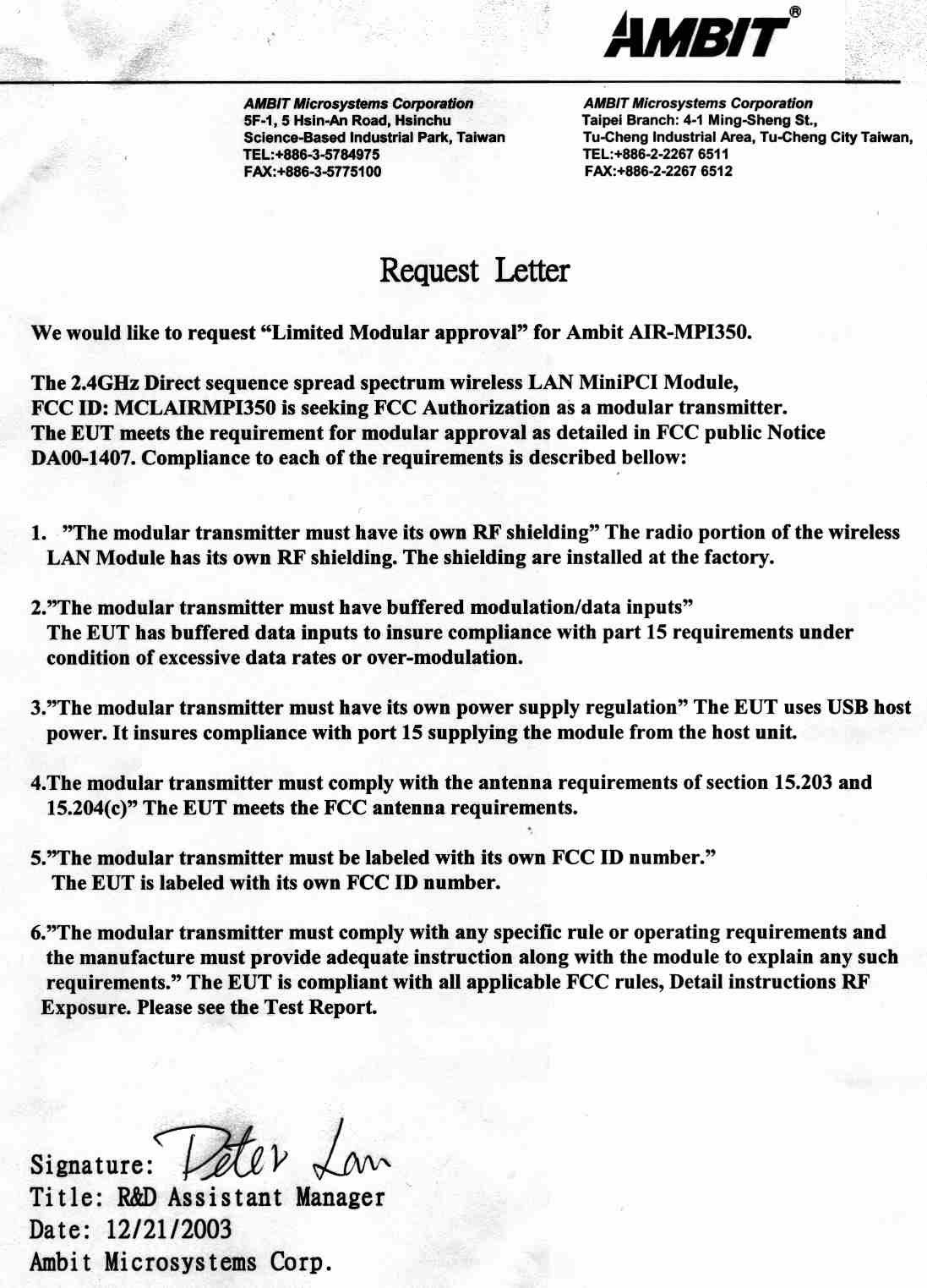
Document Text
Text extracted from the exhibit documents filed with the FCC. Open a document above to read the original.
Users Manual
1 User Manual Wireless MiniPCI Card Model Name: AIR-MPI350 2 Contents Chapter 1 About the U58H004 MiniPCI Card 1-1 Features 1-2 Applications 1-3 Product Kit Chapter 2 Network Configuration and Planning 2-1 Network Topology 2-2 Roaming Chapter 3 Adapter Installation and Configuration – Windows ® 98 / NT / 2000 3-1 System Requirements 3-2 Inserting the Adapter 3-3.1 U58H004 Driver Installation - Windows ® 98 3-3.2 Adapter Configuration - Windows ® 98 3-3.3 Protocol Installation - Windows ® 98 3-4 U58H004 Setup for Windows ® 2000 Appendix A Troubleshooting Appendix B Glossary 3 Chapter 1 About the U58H004 MiniPCI Card The IEEE 802.11 U58H004 MiniPCI Card is compatible with any standard, notebook computer Type III MiniPCI slot. As a Plug-and-Play device, Windows 95/98/2000 will automatically recognize the U58H004 MiniPCI Card and initiate the installation process. Upon successful installation, the U58H004 MiniPCI card will communicate seamlessly with other U58H004 wireless home and office networking products. 1-1 FEATURES 1. Supports up to 11 Mbps data rate: T-1 line alternative/replacement that dramatically cuts costs. 2. Working range up to 800 ft. in an open environment enhances mobility. 3. Supports point-to-point and point-to-multipoint access provides increased flexibility. 4. Seamless connectivity to wired Ethernet and PC network LAN’s offers quick, trouble-free integration with existing networks. 5. Robust Direct Sequence Spread Spectrum (DSSS) technology provides secure, interference-resistant wireless connection. 6. Wireless connections eliminate the hassle and cost of cabling. 7. Supports a wide range of LAN (Local Area Network) Network Operating Systems (NOS) including Windows ® 98 and Windows ® 2000 8. Easy Plug and Play installation(U58H004.00). 9. Omni - directional antenna included 10. Greater flexibility to locate or move networked PC’s 1-2 APPLICATIONS U58H004 products offer a fast, reliable, cost-effective solution for wireless client access to the network the following applications and environments: Remote access to corporate network information E-mail, file transfer and terminal emulation Difficult-to-wire environments Historic or older buildings Buildings with asbestos insulation Open areas where wiring is difficult to employ Frequently changing environments Retailers, manufacturers or other organizations that frequently rearrange the workplace or relocate Temporary LANs for special projects or peak time usage Trade shows, exhibitions and construction sites that employ temporary networks. 4 Retailers, airline and shipping companies that need additional workstations for a peak period and Auditors that require workgroups at customer sites. Access to database for mobile workers Medical, Technical and Retail specialists that require roaming access to a database or other network resources. SOHO (Small Office and Home Office) users Perfect for users that need a small, easy-to-install network that deploys rapidly. Inter-building connection Wireless building-to-building networks are quickly and easily installed, require no monthlylease fees, and provide the flexibility to reconfigure easily. 1-3 PRODUCT KIT The U58H004 product kit includes the following items. Ensure that the items in the following list have been included. If any of the listed items are missing, please contact your local dealer. 1 X Type III U58H004 MiniPCI Adapter 1 X Driver 1 X User Manual & Utility 5 Chapter 2 Network Configuring and Planning The U58H004 supports legacy Ethernet LAN network configuration options as defined by the IEEE 802.11 standards committee. The U58H004 can be configured as: . Ad-Hoc for departmental or SOHO LANs. . Infrastructure for enterprise LANs. . LAN-Interconnection for to point-to-point link as a campus backbone. 2-1 Network Topology Ad-Hoc Wireless LAN Notebook with T60L198/T60L244 Notebook with T60L198/T60L244 Desktop PC with T60L198/T60L244 Desktop PC with T60L198/T60L244 Fig.1 Ad-Hoc Wireless LAN An Ad-Hoc wireless LAN is a group of computers. Each equipped with on U58H004 adapter, connected as an independent wireless LAN Computers in a specific Ad-Hoc wireless LAN must be configured to share the same radio channel. Ad-Hoc wireless LAN configurations are appropriate for branch level departments or SOHO operations. 6 乙太網路 File Server Desktop PC Desktop PC Desktop PC with T60L198/T60L244 Desktop PC with T60L198/T60L244 Access PointAccess Point Notebook with T60L198/T60L244 Notebook with T60L198/T60L244 Fig.2 Infrastructure Wireless LAN Configuration Desktop PC with T60L198/T60L244 Desktop PC with T60L198/T60L244 The U58H004 provides access to a wired LAN for wireless workstations. An integrated wireless and wired LAN is called an Infrastructure configuration. A group of U58H004 PC users and an Access Point compose a Basic Service Set (BSS).Each U58H004 can talk to any computer in the wired LAN infrastructure via the Access Point. An Infrastructure configuration extends the accessibility of a U58H004 equipped PC to a wired LAN and doubles the effective wireless transmission range for 2 U58H004 PCs. Since the Access Point is able to forward data within its BSS, the effective transmission range in an infrastructure LAN is doubled. Ad-Hoc Infrastructure Access Point Notebook with T60L198/T60L244 Notebook with T60L198/T60L244 Notebook with T60L198/T60L244 Notebook with T60L198/T60L244 Fig 3 The effective transmission ranges 7 2-2 Roaming Infrastructure mode also supports roaming capabilities for mobile users More than one BSS can be configured as an Extended Service Set (ESS). The continuous network allows users to roam freely within an ESS. All U58H004 PCs and Access Point within one ESS must be configured with the same ESSID and use the same radio channel. Ess BSS1 BSS2 乙太網路 File Server Desktop PC Desktop PC Desktop PC with T60L198/T60L244 Desktop PC with T60L198/T60L244 Access PointAccess Point Notebook with T60L198/T60L244 Notebook with T60L…
Text truncated - open the document above for the full version.
Cover Letter(s)
Federal Communication Commission Authorization and Evaluation Division Confidentiality Request regarding application for certification of FCC ID: MCLAIRMPI350 Pursuant to Sections 0.457 and 0.459 of the Commission’s Rules, we hereby request confidential treatment of information accompanying this application as outlined below: 1. Circuit Diagram 2. Block Diagram 3. Operational Description The above materials contain trade secrets and proprietary information not customarily released to the public. The public disclosure of these materials may be harmful to the applicant and provide unjustified benefits to its competitors. The application understands that pursuant to Section 0.457 of the Rules, disclosure of this application and all accompanying documentation will not be made before the date of the Grant for this application. Sincerely,
External Photos
EXHIBIT C - EUT PHOTOGRAPHS Top View Bottom View Shield Removed Top View Dual Band Antenna - M&A View Film Antenna - M View Film Antenna - A View Stick Antenna - M View Stick Antenna - a View
ID Label/Location Info
EXHIBIT A - FCC ID LABEL INFORMATION Proposed FCC ID Label Approximate size: 2.875 cm long and 0.833 cm wide Proposed Label Location on EUT Bottom Side of EUT/FCC ID Label FCC ID: MCLAIRMPI350 This device complies with Part 15 of the FCC Rules. Operation is subject to the following two conditions: (1) this device may not cause harmful interference, and (2) this device must accept any interference received, including interference that may cause undesired operation.
Internal Photos
EXHIBIT C - EUT PHOTOGRAPHS Top View Bottom View Shield Removed Top View Dual Band Antenna - M&A View Film Antenna - M View Film Antenna - A View Stick Antenna - M View Stick Antenna - a View
Test Report
Note: This test report is specially limited to the above client company and the product model only. It may not be duplicated without prior written consent of Bay Area Compliance Laboratory Corporation. This report must not be used by the client to claim product endorsement by NVLAP or any agency of the U.S. Government. FCC PART 15 SUBPART C EMI MEASUREMENT AND TEST REPORT For AMBIT Microsystems Corporation 4-1, Ming Shen Street, Tu Chen Industrial District. Tu Chen, Taipei Hsien 236, Taiwan, R.O.C. FCC ID: MCLAIRMPI350 July 17, 2002 This Report Concerns: Original Report Equipment Type: Wireless MiniPCI Card Test Engineer: Benjamin Jin Report No.: R0206144 Test Date: June 26, 2002 Reviewed By: Jeff Lee Prepared By: Bay Area Compliance Laboratory Corporation 230 Commercial Street Sunnyvale, CA 94085 Tel: (408) 732-9162 Fax: (408) 732 9164 AMBIT Microsystems Corporation FCC ID: MCLAIRMPI350 Report # R0206144Rpt 15.247 Test Report Page 2 of 27 TABLE OF CONTENTS 1 - GENERAL INFORMATION..................................................................................................................................4 1.1 PRODUCT DESCRIPTION FOR EQUIPMENT UNDER TEST (EUT) ..............................................................................4 1.2 OBJECTIVE.............................................................................................................................................................4 1.3 RELATED SUBMITTAL(S)/GRANT(S).......................................................................................................................5 1.4 TEST METHODOLOGY............................................................................................................................................5 1.5 TEST FACILITY.......................................................................................................................................................5 1.6 TEST EQUIPMENT LIST AND DETAILS.....................................................................................................................6 1.7 LOCAL SUPPORT EQUIPMENT LIST AND DETAILS...................................................................................................6 2 - SYSTEM TEST CONFIGURATION.....................................................................................................................7 2.1 JUSTIFICATION.......................................................................................................................................................7 2.2 EUT EXERCISE SOFTWARE....................................................................................................................................7 2.3 SPECIAL ACCESSORIES...........................................................................................................................................7 2.4 SCHEMATICS / BLOCK DIAGRAM...........................................................................................................................7 2.5 EQUIPMENT MODIFICATIONS.................................................................................................................................7 2.6 CONFIGURATION OF TEST SYSTEM.........................................................................................................................8 2.7 TEST SETUP BLOCK DIAGRAM...............................................................................................................................8 3 - SUMMARY OF TEST RESULTS..........................................................................................................................9 4 - PEAK OUTPUT POWER MEASUREMENT ....................................................................................................10 4.1 STANDARD APPLICABLE......................................................................................................................................10 4.2 MEASUREMENT PROCEDURE................................................................................................................................10 4.3 MEASUREMENT RESULT......................................................................................................................................10 4.4 PLOT OF MAXIMUM PEAK OUTPUT POWER..........................................................................................................10 5 - SPURIOUS EMISSION.........................................................................................................................................11 5.1 STANDARD APPLICABLE......................................................................................................................................11 5.2 MEASUREMENT PROCEDURE................................................................................................................................11 5.3 MEASUREMENT RESULT......................................................................................................................................11 6 - PEAK POWER SPECTRAL DENSITY ..............................................................................................................12 6.1 STANDARD APPLICABLE......................................................................................................................................12 6.2 MEASUREMENT PROCEDURE................................................................................................................................12 6.3 MEASUREMENT RESULTS.....................................................................................................................................12 6.4 PLOT OF PEAK POWER SPECTRAL DENSITY.........................................................................................................12 7 - 6 DB BANDWIDTH...............................................................................................................................................13 7.1 STANDARD APPLICABLE................…
Text truncated - open the document above for the full version.
Test Setup Photos
EXHIBIT B - TEST SETUP PHOTOGRAPHS Conducted Emission - Front View Conducted Emission - Rear View Radiated Emission - Front View Radiated Emission - Rear View
Contact Information
Applicant
Mrs. Rio Chen(Compliance Deputy Manager)
Test Firm
Bay Area Compliance LaboratoryJohn Chan
Technical Specifications
| # | Rule Parts | Frequency Range | Power Output |
|---|---|---|---|
| 1 | 15C | 2.41 GHz - 2.47 GHz | 14.00 mW |
Other Applications from HON HAI Precision Ind. Co., Ltd.

MCLT77W968
Jun 03, 2021LTE M.2 Module
Equipment Class
CBE - Citizens Band End User Devices
MCLT77W968C9
Feb 13, 2020LTE M.2 Module
Equipment Class
PCB - PCS Licensed Transmitter
MCLADB1761WF
Jun 03, 2015IP Set-Top Box with Wi-Fi 11ac
Equipment Class
DTS - Digital Transmission System
MCLADB1761W
Jun 02, 2015IP Set-Top Box
Equipment Class
DTS - Digital Transmission System
MCLT77H566
Feb 16, 2015WiFi/BT Module
Equipment Class
DTS - Digital Transmission System