MCLJ07H06902Notebook Computer With 802.11 b/g Module
HON HAI Precision Ind. Co., Ltd.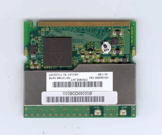
Click to zoom
Application Details
- Equipment Class
- DTS - Digital Transmission System
- Date of Grant
- Mar 25, 2003
- Application Purpose
- Original Equipment
- Date of Application
- Mar 25, 2003
- Equipment Note
- Notebook Computer With 802.11 b/g Module
- Frequency Range
- 2412.00000000 - 2462.00000000
- Country
- Taiwan
Documents & Files
Document Text
Text extracted from the exhibit documents filed with the FCC. Open a document above to read the original.
Users Manual
DRAFT - Revised: 11-17-02 Compaq CONFIDENTIAL—For Internal Use Only 11/12/02 File: Sapphire-Intro.fm b Hardware Guide Sapphire Document Part Number: 309971-001 April 2003 [Abstract goes here, or delete this line.] DRAFT - Revised: 11-17-02 Compaq CONFIDENTIAL—For Internal Use Only 11/12/02 File: Sapphire-Intro.fm © 2003 HP HP notice Hardware Guide First Edition February 2003 Document Part Number: 309971-001 DRAFT - Revised: 10-28-02 Hardware Guideiii Compaq CONFIDENTIAL—For Internal Use Only 11/13/02 File: 309971-001TOC.fm Contents 1 Notebook Features Contents of the Packing Box . . . . . . . . . . . . . . . . . . . . . . 1–1 Notebook Features . . . . . . . . . . . . . . . . . . . . . . . . . . . . . . 1–2 Pointing Device Components . . . . . . . . . . . . . . . . . . 1–2 Top Components . . . . . . . . . . . . . . . . . . . . . . . . . . . . 1–3 Left Side Components . . . . . . . . . . . . . . . . . . . . . . . . 1–5 Right Side Components . . . . . . . . . . . . . . . . . . . . . . . 1–6 Front View Components . . . . . . . . . . . . . . . . . . . . . . 1–7 Rear Panel Components. . . . . . . . . . . . . . . . . . . . . . . 1–8 Bottom Components . . . . . . . . . . . . . . . . . . . . . . . . . 1–9 Lights . . . . . . . . . . . . . . . . . . . . . . . . . . . . . . . . . . . . 1–10 2 Pointing Devices and Keyboard Using a Pointing Device. . . . . . . . . . . . . . . . . . . . . . . . . . 2–1 Using the Pointing Stick . . . . . . . . . . . . . . . . . . . . . . 2–2 Using the TouchPad. . . . . . . . . . . . . . . . . . . . . . . . . . 2–3 Using an External Mouse . . . . . . . . . . . . . . . . . . . . . 2–3 Setting Pointing Device Preferences . . . . . . . . . . . . . 2–4 Using Hotkeys and Shortcut Keys . . . . . . . . . . . . . . . . . . 2–5 Fn and Function Keys . . . . . . . . . . . . . . . . . . . . . . . . 2–5 Hotkey and Shortcut Key Quick Reference . . . . . . . 2–6 Display Help (Fn+F1) . . . . . . . . . . . . . . . . . . . . . . . . 2–6 Initiate Standby (Fn+F3) . . . . . . . . . . . . . . . . . . . . . . 2–7 Switching Display and Image (Fn+F4) . . . . . . . . . . . 2–7 Initiating Quick Controls (Fn+F6). . . . . . . . . . . . . . . 2–8 Viewing Battery Charge Information (Fn+F8) . . . . . 2–8 Adjusting the Screen Brightness (Fn+F9 and Fn+F10) . . . . . . . . . . . . . . . . . . . . . . . . . . . . . . . . . . . 2–8 ivHardware Guide DRAFT - Revised: 10-28-02 Compaq CONFIDENTIAL—For Internal Use Only 11/13/02 File: 309971-001TOC.fm Displaying System Information (Fn+Esc) . . . . . . . . . 2–8 Using Hotkeys and Shortcut Keys with External Keyboards . . . . . . . . . . . . . . . . . . . . . . . . . . 2–9 Using Quick Launch Buttons . . . . . . . . . . . . . . . . . . . . . 2–10 Keypads . . . . . . . . . . . . . . . . . . . . . . . . . . . . . . . . . . . . . 2–11 Using the Internal Keypad . . . . . . . . . . . . . . . . . . . . 2–11 Using an External Keypad . . . . . . . . . . . . . . . . . . . . 2–13 3 Battery Packs Inserting or Removing the Primary Battery Pack . . . . . . 3–2 Using the Optional Travel Battery . . . . . . . . . . . . . . . . . . 3–4 Inserting or Removing the Battery Pack . . . . . . . . . . 3–4 Attaching or Detaching the Travel Battery and the Notebook . . . . . . . . . . . . . . . . . . . . . . . . . . . . . . . 3–6 Charging a Battery Pack. . . . . . . . . . . . . . . . . . . . . . . . . . 3–9 Monitoring the Charge of a Battery Pack . . . . . . . . . . . 3–11 Displaying Charge Information on the Screen . . . . 3–12 Displaying Charge Information on a Battery Pack. . . . . . . . . . . . . . . . . . . . . . . . . . . . . . . 3–13 Managing Low-Battery Conditions . . . . . . . . . . . . . . . . 3–14 Identifying Low-Battery Conditions . . . . . . . . . . . . 3–14 Resolving Low-Battery Conditions . . . . . . . . . . . . . 3–15 Calibrating a Battery Pack . . . . . . . . . . . . . . . . . . . . . . . 3–16 When to Calibrate . . . . . . . . . . . . . . . . . . . . . . . . . . 3–16 How to Calibrate . . . . . . . . . . . . . . . . . . . . . . . . . . . 3–17 Conserving Battery Power . . . . . . . . . . . . . . . . . . . . . . . 3–19 Conserving Power as You Work . . . . . . . . . . . . . . . 3–19 Selecting Power Conservation Settings . . . . . . . . . . 3–20 Storing a Battery Pack . . . . . . . . . . . . . . . . . . . . . . . . . . 3–21 Disposing of a Used Battery Pack . . . . . . . . . . . . . . . . . 3–22 Finding More Power Information . . . . . . . . . . . . . . . . . 3–22 Hardware Guidev DRAFT - Revised: 10-28-02 Compaq CONFIDENTIAL—For Internal Use Only 11/13/02 File: 309971-001TOC.fm 4 Hard Drive Caring for Drives . . . . . . . . . . . . . . . . . . . . . . . . . . . . . . . 4–1 Hard Drive Activity Light . . . . . . . . . . . . . . . . . . . . . . . . 4–2 Replacing the Primary Hard Drive. . . . . . . . . . . . . . . . . . 4–2 5 Audio and Video Using Audio Features. . . . . . . . . . . . . . . . . . . . . . . . . . . . 5–1 Adjusting Volume . . . . . . . . . . . . . . . . . . . . . . . . . . . 5–2 Using the Audio Line-In Jack . . . . . . . . . . . . . . . . . . 5–3 Using the Audio Line-Out Jack . . . . . . . . . . . . . . . . . 5–3 Using Video Features . . . . . . . . . . . . . . . . . . . . . . . . . . . . 5–3 Connecting a Device to the S-Video-Out Jack . . . . . 5–4 Changing the Video Mode. . . . . . . . . . . . . . . . . . . . . 5–5 6 Communication Devices Connecting a Modem Cable. . . . . . . . . . . . . . . . . . . . . . . 6–1 Using the RJ-11 Cable . . . . . . . . . . . . . . . . . . . . . . . . 6–3 Using a Country-Specific Adapter Cable . . . . . . . . . 6–4 Connecting a Network Cable . . . . . . . . . . . . . . . . . . . . . . 6–5 Linking to an Infrared Device . . . . . . . . . . . . . . . . . . . . . 6–6 Setting Up an Infrared Transmission. . . . . . . . . . . . . 6–7 Using Standby with Infrared . . . . . . . . . . . . . . . . . . . 6–8 Using Wireless LAN . . . . . . . . . . . . . . . . . . . . . . . . . . . . 6–8 7 External Devices Connecting a Monitor or Projector . . . . . . .…
Text truncated - open the document above for the full version.
Users Manual
HP WLAN 802.11b/g User Manual Chapter 1 About the HP WLAN 802.11b/g device....................................................3 1-1 Introduction...........................................................................................................3 1-2 Using a Wireless Local Area Network.................................................................3 1-3 Features and Requirements...................................................................................4 Chapter 2 Network Configuring and Planning............................................................5 2-1 Ad-Hoc Network..................................................................................................5 2-2 Access Point (Infrastructure) Network.................................................................6 Chapter 3 Atheros Client Utility Installation...............................................................7 3-1 Atheros Client Utility Installation........................................................................7 Chapter 4 Atheros Client Utility (ACU) Configuration............................................10 4-1 Atheros Client Utility icon.................................................................................10 4-2 Current Status Tab...............................................................................................11 4-3 Profile Management............................................................................................13 4-3-1 Create or Modify a Profile.......................................................................14 4-3-2 Security Settings in Profile Management................................................16 4-3-3 Advanced settings in Profile Management..............................................20 4-4 Diagnostic Tab....................................................................................................21 4-5 Action Menu.......................................................................................................22 4-5-1 Enable/Disable Radio..............................................................................22 4-5-2 Enable/Disable Tray Icon........................................................................22 Chapter 5 Wireless Configuration using Windows XP.....................................................23 5-1 Configuring Your Wireless Networking Settings...............................................23 5-2 Advanced Wireless Settings...............................................................................23 5-3 Disabling the Radio............................................................................................24 5-4 Help and Support Information............................................................................24 Appendix A - Atheros Client Utility Uninstall Process....................................................25 Appendix B - Glossary......................................................................................................28 Appendix C – Wireless Notice..........................................................................................29 Chapter 1 About the HP WLAN 802.11b/g device 1-1 Introduction The HP WLAN 802.11b/g device allows you to access Wireless Local Area Networks (WLANs), share a local printer and files with others in your network, access the Internet, and roam about the office—wirelessly. This wireless Local Area Network solution is designed for both large and small businesses, and it is scalable so that you can add users and new network features as your networking needs grow. The HP WLAN 802.11b/g device is a 2.4Ghz WLAN technology that will operate with at a maximum data rate of 11Mbps with 802.11b and maximum data rate of 54Mbps with 802.11g wireless networks. The HP WLAN 802.11b/g device will automatically detect and seamlessly roam between both 802.11b and 802.11g wireless networks. 1-2 Using a Wireless Local Area Network A wireless LAN provides the same functionality of a wired network, but it eliminates the need to install networking cables and other networking equipment. Not only is a wireless LAN easier to deploy, but it also allows for mobility through “roaming.” For example the HP WLAN 802.11b/g device can roam from a conference room to an office without being disconnected from the network. 1-3 Features and Requirements The HP WLAN 802.11b/g device includes the following features: Wireless Features • Support for the IEEE 802.11b standard • Support for the IEEE 802.11g standard • Operates within the 2.4-GHz band • Maximum data rate of up to 11 Mbps (802.11b) • Maximum data rate of up to 54 Mbps (802.11g) Interoperability • WiFi certified at 2.4GHz to ensure wireless interoperability with other WiFi (802.11b) certified devices. Security • Cisco Client Extension compatibility (including LEAP) • Wired Equivalent Privacy (WEP) encryption, operating with 64bit, 128bit or 152 bit encryption • AES-CCM Encryption support • Support for Windows 802.1X supplicants Chapter 2 Network Configuring and Planning A wireless LAN can be configured for two different modes of operation. While each method has its advantages, one may be better suited for your needs. Review the following configurations to determine which mode is best for you. • Ad-Hoc Network • Access Point (Infrastructure) Network 2-1 Ad-Hoc Network An Ad-Hoc network is the simplest to deploy and is ideal for small offices. Ad-Hoc wireless networks can be comprised of two or more wireless client configured to communicate with one another. All Ad-hoc clients communicate directly with each other without using an access point (AP). As a user on this type of network, you are able to quickly build up a wireless network in order to share files with other employees, print to a shared office printer, and access the Internet through a single shared connection. Ad-hoc networking is cost effective, because no other devices components are needed (access points, hubs or routers) in order to setup a ne…
Text truncated - open the document above for the full version.
Attestation Statements
~7837589 (3373x4640x2 bmp)
Cover Letter(s)
Feb. 06, 2003 Federal Communications Commission Authorization and Evaluation Division 7435 Oakland Mills Road Columbia, MD 21046 Re: Request for Confidentiality In reference to the application under FCC ID: (MCLJ07H069.02), and pursuant to Sections 0.457(d)(1)(ii) and 0.459 of the Commission's Rules, the Applicant hereby requests confidential treatment of the accompanying information as outlined below: Block Diagram Schematics Theory of Operation The above materials contain trade secrets and proprietary information not customarily released to the public. The public disclosure of these matters might be harmful to the Applicant and provide unjustified benefits to its competitors. The Applicant understands that pursuant to Rule 0.457(d)(1)(ii), disclosure of this Application and all accompanying documentation will not be made before the date of the Grant for this application. Sincerely, Ronnie Cheng / Senior Engineer Communication R&D Dept. 2 of Div. 1 AMBIT Microsystems Corporation
Cover Letter(s)
From: Helen Zhao Sent: Thursday, March 20, 2003 12:32 PM To: Mike Kuo Cc: Michael Heckrotte; Steve Cheng Subject: FW: Ambit Microsystems Corporation, FCC ID:MCLJ07H06902, AN03T2659 (resend) Hello Mike, Regarding this submission (b/g portable), here is a final response to all questions: Question #1: Please provide external photos of notebook computer ( Agency Series PP2170 ) Here is external photos of notebook computer. Question #2: Please provide internal photos of notebook computer ( Agency Series PP2170) Here is external photos of notebook computer. Question #3: Since there is no portable module approval, the device contains in this TCB application will be reviewed as Agency Series PP2170 Laptop computer with 802.11/b mini PCI module build in. The FCC ID label shall be placed on the laptop. Please provide revised FCC ID label format and label location. Here is revised FCC ID Label and location. Question #4: Please provide complete user manual for notebook computer with WLAN . Please make sure to include necessary RF exposure warning statement. Here are users manual for notebook computer Sapphire PP2170 and revised manual for b/g WLAN. Question #5: There is no SAR test report provided. Only SAR test plots, system validation plots and calibration files are provided. Here is SAR Report. Question #6: Please provide internal photos of notebook computer with indication of antenna location within the notebook. Here is internal photos of notebook computer with indication of antenna location within the notebook. Question #7: Please remove section 8.5 of test report. MPE estimate does not apply to portable device. Here is the revised test report. Question #8: In accordance with Radiated test setup photos, the tests were performed with antennas placed on outside of notebook computer. Such test configuration can only be used for Mobile transmitter module configuration. When the device is portable device, the radiated spurious emission tests must be performed when the antennas are installed inside the notebook computer. Please redo the spurious radiated emission tests. Here is the revised setup photos Question #9: Page 67-69, 78-81 of EMC test report can not be read. Please provide a clear copy of test report. Please refer to the revised test report (#7) . Question #10: Please provide FCC DoC test report or FCC DoC statement of Notebook Computer Here is FCC DoC statement of Notebook Computer. Just for your information, here I re-submit revised Theory of Operation: Thank you! Helen
ID Label/Location Info
PROPOSED FCC ID LABEL AND LOCATION Ambit Microsystems Corporation This device complies with Part 15 of the FCC Rules. Operation is subject to the following two conditions: (1) this device may not cause harmful interference, and (2) this device must accept any interference received, including interference that may cause undesired operation. FCC ID: MCLJ07H06902 FCC ID LABEL LOCATION
Parts List/Tune Up Info
View With Cable and Module View With Cable and Module >20cm Antenna Antenna View With Antenna installed in the Panel View with Loaded Plane Antenna Antenna Right Antenna Close View Left Antenna Close View
RF Exposure Info
in accordance with the requirements of FCC Report and Order: ET Docket 93-62, and OET Bulletin 65 Supplement C for 802.11b/g Mini-PCI Card With Agency Series PP2170 Laptop MODEL: J07H069.02 FCC ID: MCLJ07H06902 February 3, 2003 REPORT NO: 03U1761-3 Prepared for Ambit Microsystems Corporation 5F-1, 5 Hsin-An Road Hsinchu, Science-Based Industrial Park Taiwan, R. O. C. Prepared by COMPLIANCE CERTIFICATION SERVICES 561F MONTEREY ROAD MORGAN HILL, CA 95037 USA TEL: (408) 463-0885 REPORT NO: 03U1761-3 DATE: February 3, 2003 FCC ID: MCLJ07H06902 COMPLIANCE CERTIFICATION SERVICES Page: 2 of 25 This report shall not be reproduced except in full, without the written approval of CCS. This document may be altered or revised by Compliance Certification Services personnel only, and shall be noted in the revision section of the document. CERTIFICATE OF COMPLIANCE (SAR EVALUATION) Date of Tests: January 31 - February 3, 2003 Report No: 03U1761-3 APPLICANT: Ambit Microsystems Corporation 5F-1, 5 Hsin-An Road Hsinchu, Science-Based Industrial Park Taiwan, R.O.C. MODEL: J07H069.02 FCC ID: MCLJ07H06902 DEVICE CATEGORY: PORTABLE DEVICES EXPOSURE CATEGORY: GENERAL POPULATION/UNCONTROLLED EXPOSURE Test Sample is a: Production unit Modulation type: Digital Modulation (DSSS/OFDM) Operating mode: Maximum continuous output Tx Frequency: 2412 – 2462MHz Max. O/P Power (Conducted): 802.11b - 20.64 dBm (2412 MHz) 802.11g - 21.92 dBm (2437 MHz) Max. SAR (1g): 802.11b - 0.359 mW/g (2412 MHz) 802.11g - 0.345 mW/g (2412 MHz) Application Type: Certification FCC Rule Part(s): §15.247 Note: This wireless portable device has been shown to be capable of compliance for localized specific absorption rate (SAR) for uncontrolled environment/general population exposure limits specified in ANSI/IEEE Std. C95.1-1992 and had been tested in accordance with the measurement procedures specified in FCC OET 65 Supplement C (released on 6/29/2001 see Test Report). I attest to the accuracy of data. All measurements reported herein were performed by me or were made under my supervision and are correct to the best of my knowledge and belief. I assume full responsibility for the completeness of these measurements and vouch for the qualifications of all persons taking them. Steve Cheng EMC Engineering Manager REPORT NO: 03U1761-3 DATE: February 3, 2003 FCC ID: MCLJ07H06902 COMPLIANCE CERTIFICATION SERVICES Page: 3 of 25 This report shall not be reproduced except in full, without the written approval of CCS. This document may be altered or revised by Compliance Certification Services personnel only, and shall be noted in the revision section of the document. TABLE OF CONTENT 1. EUT DESCRIPTION ............................................................................................. 4 2. REQUIREMENTS FOR COMPLIANCE TESTING DEFINED BY THE FCC ............... 5 3. DOSIMETRIC ASSESSMENT SYSTEM ................................................................ 5 3.1. MEASUREMENT SYSTEM DIAGRAM.............................................................................................6 3.2. SYSTEM COMPONENTS.................................................................................................................7 4. EVALUATION PROCEDURE ................................................................................ 9 5. MEASUREMENT UNCERTAINTY ....................................................................... 12 6. EXPOSURE LIMIT ............................................................................................. 13 7. MEASUREMENT RESULTS ............................................................................... 14 7.1. SYSTEM VALIDATION ...................................................................................................................14 7.2. TEST LIQUID CONFIRMATION .....................................................................................................15 7.3. EUT TUNE-UP PROCEDURE ........................................................................................................16 7.4. EUT SETUP PHOTOS....................................................................................................................17 7.5. SAR MEASUREMENT RESULTS ..................................................................................................19 7.5.1. 802.11b ..................................................................................................19 7.5.2. 802.11g ..................................................................................................20 8. EUT PHOTOS .................................................................................................... 21 9. EQUIPMENTS LIST & CALIBRATION STATUS .................................................. 23 10. REFERENCES .................................................................................................. 24 11. ATTACHMENTS ................................................................................................ 25 REPORT NO: 03U1761-3 DATE: February 3, 2003 FCC ID: MCLJ07H06902 COMPLIANCE CERTIFICATION SERVICES Page: 4 of 25 This report shall not be reproduced except in full, without the written approval of CCS. This document may be altered or revised by Compliance Certification Services personnel only, and shall be noted in the revision section of the document. 1. EUT DESCRIPTION APPLICANT: Ambit Microsystems Corporation 5F-1, 5 Hsin-An Road Hsinchu, Science-Based Industrial Park Taiwan, R.O.C. MODEL: J07H069.02 FCC ID: MCLJ07H06902 DEVICE CATEGORY: PORTABLE DEVICES EXPOSURE CATEGORY: GENERAL POPULATION/UNCONTROLLED EXPOSURE Test Sample is a: Production unit Modulation type: Digital Modulation(DSSS/OFDM) Operating mode: Maximum continuous output Tx Frequency: 2412 – 2462MHz Max. O/P Power (Conducted): 802.11b - 20.64 dBm (2412 MHz) 802.11g - 21.92 dBm (2437 MHz) Max. SAR (1g): 802.11b - 0.359 mW/g (2412 MHz) 802.11g - 0.345 mW/g (2412 MHz) Application Type: Certification FCC Rule Part(s): §…
Text truncated - open the document above for the full version.
RF Exposure Info
Date/Time: 01/31/03 11:16:28 Test Laboratory: Compliance Certification Services File Name: D2450V2_013103_14.2mW.da4 DUT: Dipole Type & Serial Number: D2450V2 SN 706 Program: System Validation; I/P Power: 250mW Communication System: D2450V2 SN 706; Frequency: 2450 MHz; Duty Cycle: 1:1 Medium: Head 2450 MHz ( σ = 1.8877 mho/m, ε = 39.87, ρ = 1000 kg/m3) Phantom section: FlatSection DASY4 Configuration: - Probe: ET3DV6 - SN1578; ConvF(4.5, 4.5, 4.5); Calibrated: 2/22/2002 - Sensor-Surface: 4mm (Mechanical Surface Detection) - Electronics: DAE3 Sn500; Calibrated: 2/26/2002 - Phantom: SAM 1 - TP: 1185 - Software: DASY4, V4.0 Build 51 Zoom Scan (5x5x7)/Cube 0: Measurement grid: dx=7.5mm, dy=7.5mm Reference Value = 87.6 V/m Peak SAR = 38.8 mW/g SAR(1 g) = 14.2 mW/g; SAR(10 g) = 5.94 mW/g Power Drift = -0.01 dB Area Scan (9x9x1): Measurement grid: dx=10mm, dy=10mm SAR in dB -21.3 -18.9 -16.6 -14.2 -11.8 -9.46 -7.1 -4.73 -2.37 0 Date/Time: 02/03/03 10:47:00 Test Laboratory: Compliance Certification Services File Name: D2450V2_020303_14.1mW.da4 DUT: Dipole Type & Serial Number: D2450V2 SN 706 Program: System Validation; I/P Power: 250mW Communication System: D2450V2 SN 706; Frequency: 2450 MHz; Duty Cycle: 1:1 Medium: Head 2450 MHz ( σ = 1.8809 mho/m, ε = 39.98, ρ = 1000 kg/m3) Phantom section: FlatSection DASY4 Configuration: - Probe: ET3DV6 - SN1578; ConvF(4.5, 4.5, 4.5); Calibrated: 2/22/2002 - Sensor-Surface: 4mm (Mechanical Surface Detection) - Electronics: DAE3 Sn500; Calibrated: 2/26/2002 - Phantom: SAM 1 - TP: 1185 - Software: DASY4, V4.0 Build 51 Zoom Scan (5x5x7)/Cube 0: Measurement grid: dx=7.5mm, dy=7.5mm Reference Value = 87.6 V/m Peak SAR = 38.7 mW/g SAR(1 g) = 14.1 mW/g; SAR(10 g) = 5.92 mW/g Power Drift = -0.01 dB Area Scan (9x9x1): Measurement grid: dx=10mm, dy=10mm SAR in dB -21.3 -18.9 -16.6 -14.2 -11.8 -9.46 -7.1 -4.73 -2.37 0
RF Exposure Info
Date/Time: 01/31/03 13:23:44 Test Laboratory: Compliance Certification Services File Name: 1_L-CH_0.359mW.da4 EUT setup configuration 1 & 2 related scan grid (View from bottom of the phantom) SAR in dB -18.5 -16.5 -14.4 -12.4 -10.3 -8.24 -6.18 -4.12 -2.06 0 Date/Time: 01/31/03 13:23:44 Test Laboratory: Compliance Certification Services File Name: 1_L-CH_0.359mW.da4 DUT: Ambit Type & Serial Number: J07H069.02 Program: EUT Configuration 1; 802.11b, Low channel 2412 MHz, Antenna A Communication System: DSSS; Frequency: 2412 MHz; Duty Cycle: 1:1 Medium: Muscle 2450 MHz ( σ = 1.9927 mho/m, ε = 51.33, ρ = 1000 kg/m3) Phantom section: FlatSection DASY4 Configuration: - Probe: ET3DV6 - SN1578; ConvF(4.1, 4.1, 4.1); Calibrated: 2/22/2002 - Sensor-Surface: 4mm (Mechanical Surface Detection) - Electronics: DAE3 Sn500; Calibrated: 2/26/2002 - Phantom: - TP:SAM 2 - Software: DASY4, V4.0 Build 51 Zoom Scan (5x5x7)/Cube 0: Measurement grid: dx=7.5mm, dy=7.5mm Reference Value = 6.88 V/m Peak SAR = 0.939 mW/g SAR(1 g) = 0.359 mW/g; SAR(10 g) = 0.176 mW/g Power Drift = 0.13 dB Area Scan (12x25x1): Measurement grid: dx=10mm, dy=10mm SAR in dB -18.5 -16.5 -14.4 -12.4 -10.3 -8.24 -6.18 -4.12 -2.06 0 Date/Time: 01/31/03 14:30:32 Test Laboratory: Compliance Certification Services File Name: 2_M-CH_0.356mW.da4 DUT: Ambit Type & Serial Number: J07H069.02 Program: EUT Configuration 1; 802.11b, Middle channel 2437 MHz, Antenna A Communication System: DSSS; Frequency: 2437 MHz; Duty Cycle: 1:1 Medium: Muscle 2450 MHz ( σ = 1.9927 mho/m, ε = 51.33, ρ = 1000 kg/m3) Phantom section: FlatSection DASY4 Configuration: - Probe: ET3DV6 - SN1578; ConvF(4.1, 4.1, 4.1); Calibrated: 2/22/2002 - Sensor-Surface: 4mm (Mechanical Surface Detection) - Electronics: DAE3 Sn500; Calibrated: 2/26/2002 - Phantom: - TP:SAM 2 - Software: DASY4, V4.0 Build 51 Zoom Scan (5x5x7)/Cube 0: Measurement grid: dx=7.5mm, dy=7.5mm Reference Value = 6.98 V/m Peak SAR = 0.939 mW/g SAR(1 g) = 0.356 mW/g; SAR(10 g) = 0.173 mW/g Power Drift = 0.13 dB Area Scan (12x25x1): Measurement grid: dx=10mm, dy=10mm SAR in dB -20.4 -18.3 -16.3 -14.2 -12.2 -10.2 -8.14 -6.11 -4.07 -2.04 0 Date/Time: 01/31/03 15:33:30 Test Laboratory: Compliance Certification Services File Name: 3_H-CH_0.331mW.da4 DUT: Ambit Type & Serial Number: J07H069.02 Program: EUT Configuration 1; 802.11b, High channel 2462 MHz, Antenna A Communication System: DSSS; Frequency: 2462 MHz; Duty Cycle: 1:1 Medium: Muscle 2450 MHz ( σ = 1.9927 mho/m, ε = 51.33, ρ = 1000 kg/m3) Phantom section: FlatSection DASY4 Configuration: - Probe: ET3DV6 - SN1578; ConvF(4.1, 4.1, 4.1); Calibrated: 2/22/2002 - Sensor-Surface: 4mm (Mechanical Surface Detection) - Electronics: DAE3 Sn500; Calibrated: 2/26/2002 - Phantom: - TP:SAM 2 - Software: DASY4, V4.0 Build 51 Zoom Scan (5x5x7)/Cube 0: Measurement grid: dx=7.5mm, dy=7.5mm Reference Value = 6.99 V/m Peak SAR = 0.892 mW/g SAR(1 g) = 0.331 mW/g; SAR(10 g) = 0.158 mW/g Power Drift = 0.04 dB Area Scan (12x25x1): Measurement grid: dx=10mm, dy=10mm SAR in dB -20.4 -18.3 -16.3 -14.2 -12.2 -10.2 -8.14 -6.11 -4.07 -2.04 0 Date/Time: 01/31/03 16:38:12 Test Laboratory: Compliance Certification Services File Name: 1_L-CH_0.254mW.da4 DUT: Ambit Type & Serial Number: J07H069.02 Program: EUT Configuration 2; 802.11b, Low channel 2412 MHz, Antenna B Communication System: DSSS; Frequency: 2412 MHz; Duty Cycle: 1:1 Medium: Muscle 2450 MHz ( σ = 1.9927 mho/m, ε = 51.33, ρ = 1000 kg/m3) Phantom section: FlatSection DASY4 Configuration: - Probe: ET3DV6 - SN1578; ConvF(4.1, 4.1, 4.1); Calibrated: 2/22/2002 - Sensor-Surface: 4mm (Mechanical Surface Detection) - Electronics: DAE3 Sn500; Calibrated: 2/26/2002 - Phantom: - TP:SAM 2 - Software: DASY4, V4.0 Build 51 Zoom Scan (5x5x7)/Cube 0: Measurement grid: dx=7.5mm, dy=7.5mm Reference Value = 8.94 V/m Peak SAR = 0.661 mW/g SAR(1 g) = 0.254 mW/g; SAR(10 g) = 0.127 mW/g Power Drift = 0.1 dB Area Scan (13x25x1): Measurement grid: dx=10mm, dy=10mm SAR in dB -19.5 -17.5 -15.6 -13.6 -11.7 -9.73 -7.79 -5.84 -3.89 -1.95 0 Date/Time: 01/31/03 17:45:16 Test Laboratory: Compliance Certification Services File Name: 1_L-CH_0.244mW.da4 EUT setup configuration 3 & 4 related to scan grid (View from bottom of the phantom) SAR in dB -18.5 -16.7 -14.8 -13 -11.1 -9.27 -7.42 -5.56 -3.71 -1.85 0 Date/Time: 01/31/03 17:45:16 Test Laboratory: Compliance Certification Services File Name: 1_L-CH_0.244mW.da4 DUT: Ambit Type & Serial Number: J07H069.02 Program: EUT Configuration 3; 802.11b, Low channel 2412 MHz, Antenna A Communication System: DSSS; Frequency: 2412 MHz; Duty Cycle: 1:1 Medium: Muscle 2450 MHz ( σ = 1.9927 mho/m, ε = 51.33, ρ = 1000 kg/m3) Phantom section: FlatSection DASY4 Configuration: - Probe: ET3DV6 - SN1578; ConvF(4.1, 4.1, 4.1); Calibrated: 2/22/2002 - Sensor-Surface: 4mm (Mechanical Surface Detection) - Electronics: DAE3 Sn500; Calibrated: 2/26/2002 - Phantom: - TP:SAM 2 - Software: DASY4, V4.0 Build 51 Zoom Scan (5x5x7)/Cube 0: Measurement grid: dx=7.5mm, dy=7.5mm Reference Value = 10.8 V/m Peak SAR = 0.608 mW/g SAR(1 g) = 0.244 mW/g; SAR(10 g) = 0.123 mW/g Power Drift = -0.12 dB Area Scan (11x26x1): Measurement grid: dx=10mm, dy=10mm SAR in dB -18.5 -16.7 -14.8 -13 -11.1 -9.27 -7.42 -5.56 -3.71 -1.85 0 Date/Time: 01/31/03 21:47:52 Test Laboratory: Compliance Certification Services File Name: 2_M-CH_0.241mW.da4 DUT: Ambit Type & Serial Number: J07H069.02 Program: EUT Configuration 3; 802.11b, Middle channel 2437 MHz, Antenna A Communication System: DSSS; Frequency: 2437 MHz; Duty Cycle: 1:1 Medium: Muscle 2450 MHz ( σ = 1.9927 mho/m, ε = 51.33, ρ = 1000 kg/m3) Phantom section: FlatSection DASY4 Configuration: - Probe: ET3DV6 - SN1578; ConvF(4.1, 4.1, 4.1); Calibrated: 2/22/2002 - Sensor-Surface: 4mm (Mechanical Surface Detection) - Electronics: DAE3 Sn500; Calibrated: 2/26/2002 - Phantom: - TP:SAM 2 - Software: DASY4, V4.0 Build 51 Zoom Scan (5x5x7)/Cube 0: Measurement grid: dx=7.5mm, dy=7.5mm Reference Value = 10.8 V/m Peak SAR = 0.613 mW/…
Text truncated - open the document above for the full version.
Test Report
FCC CFR47…
Text truncated - open the document above for the full version.
Contact Information
Applicant
Mrs. Rio Chen(Compliance Deputy Manager)
Test Firm
Compliance Certification Services IncSteve Cheng
Technical Specifications
| # | Rule Parts | Frequency Range | Power Output |
|---|---|---|---|
| 1 | 15C | 2.41 GHz - 2.46 GHz | 156.00 mW |
Other Applications from HON HAI Precision Ind. Co., Ltd.

MCLT77W968
Jun 03, 2021LTE M.2 Module
Equipment Class
CBE - Citizens Band End User Devices
MCLT77W968C9
Feb 13, 2020LTE M.2 Module
Equipment Class
PCB - PCS Licensed Transmitter
MCLADB1761WF
Jun 03, 2015IP Set-Top Box with Wi-Fi 11ac
Equipment Class
DTS - Digital Transmission System
MCLADB1761W
Jun 02, 2015IP Set-Top Box
Equipment Class
DTS - Digital Transmission System
MCLT77H566
Feb 16, 2015WiFi/BT Module
Equipment Class
DTS - Digital Transmission System