MCLJ07H06903802.11 a/b/g WLAN Mini-PCI Module
HON HAI Precision Ind. Co., Ltd.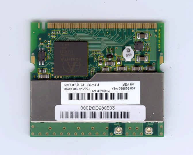
Click to zoom
Application Details
- Equipment Class
- NII - Unlicensed National Information Infrastructure TX
- Date of Grant
- Mar 26, 2003
- Application Purpose
- Original Equipment
- Date of Application
- Mar 26, 2003
- Equipment Note
- 802.11 a/b/g WLAN Mini-PCI Module
- Frequency Range
- 5260.00000000 - 5320.00000000
- Country
- Taiwan
Documents & Files
Document Text
Text extracted from the exhibit documents filed with the FCC. Open a document above to read the original.
Users Manual
HP WLAN 802.11 a/b/g User Manual Chapter 1About the HP WLAN 802.11a/b/g device ................................................. 3 1-1 Introduction .......................................................................................................... 3 1-2 Using a Wireless Local Area Network ................................................................. 3 1-3 Features and Requirements................................................................................... 4 Chapter 2Network Configuring and Planning ............................................................ 5 2-1 Ad-Hoc Network .................................................................................................. 5 2-2 Access Point (Infrastructure) Network ................................................................. 6 Chapter 3 Atheros Client Utility Installation ................................................................... 7 3-1 Atheros Client Utility Installation ........................................................................ 7 Chapter 4 Atheros Client Utility (ACU) Configuration ............................................ 10 4-1 Atheros Client Utility icon ................................................................................. 10 4-2 Current Status Tab .............................................................................................. 11 4-3 Profile Management ........................................................................................... 14 4-3-1 Create or Modify a Profile ............................................................................. 15 4-3-2 Security Settings in Profile Management........................................................ 17 4-3-3 Advanced settings in Profile Management...................................................... 21 4-4 Diagnostic Tab .................................................................................................... 22 4-5 Action Menu ....................................................................................................... 23 4-5-1 Enable/Disable Radio ...................................................................................... 23 4-5-2 Enable/Disable Tray Icon ................................................................................ 23 Chapter 5 Wireless Configuration using Windows XP..................................................... 24 5-1 Configuring Your Wireless Networking Settings ............................................... 24 5-2 Advanced Wireless Settings ............................................................................... 24 5-3 Disabling the Radio ............................................................................................ 25 5-4 Help and Support Information ............................................................................ 25 Appendix A – Atheros Client Utility Uninstall Process ................................................... 26 Appendix B - Glossary ..................................................................................................... 29 Appendix C –Wireless Notices ......................................................................................... 30 Chapter 1About the HP WLAN 802.11a/b/g device 1-1 Introduction The HP WLAN 802.11a/b/g device allows you to access Wireless Local Area Networks (WLANs), share a local printer and files with others in your network, access the Internet, and roam about the office—wirelessly. This wireless Local Area Network solution is designed for both large and small businesses, and it is scalable so that you can add users and new network features as your networking needs grow. The HP WLAN 802.11a/b/g device is a dual band WLAN device that allows for access to both 2.4Ghz and 5Ghz WLAN technologies. The HP WLAN 802.11a/b/g device will operate with at a maximum data rate of 11Mbps with 802.11b (2.4Ghz), 54Mbps with 802.11g (2.4Ghz) wireless networks and a maximum data rate of 54Mbps with 802.11a (5Ghz) wireless networks. The HP WLAN 802.11a/b/g device will automatically detect and seamlessly roam between both 802.11b (2.4Ghz), 802.11g (2.4Ghz) and 802.11a (5Ghz) wireless networks 1-2 Using a Wireless Local Area Network A wireless LAN provides the same functionality of a wired network, but it eliminates the need to install networking cables and other networking equipment. Not only is a wireless LAN easier to deploy, but it also allows for mobility through “roaming.” For example the HP WLAN 802.11a/b/g device can roam from a conference room to an office without being disconnected from the network. 1-3 Features and Requirements The HP WLAN 802.11a/b/g device includes the following features: Wireless Features • Support for the IEEE 802.11a standard • Support for the IEEE 802.11b standard • Operates within the 2.4-GHz band • Operates within the 5Ghz band • Maximum data rate of up to 54 Mbps (802.11a/g) • Maximum data rate of up to 11 Mbps (802.11b) Interoperability • WiFi certified at 5Ghz to ensure wireless interoperability with other WiFi (802.11a) certified devices. • WiFi certified at 2.4Ghz to ensure wireless interoperability with other WiFi (802.11b) certified devices. Security • Cisco Client Extension compatibility (including LEAP) • Wired Equivalent Privacy (WEP) encryption, operating with 64bit, 128bit or 152 bit encryption • AES-CCM Encryption support • Support for Windows 802.1X supplicants Chapter 2Network Configuring and Planning A wireless LAN can be configured for two different modes of operation. While each method has its advantages, one may be better suited for your needs. Review the following configurations to determine which mode is best for you. • Ad-Hoc Network • Access Point (Infrastructure) Network 2-1 Ad-Hoc Network An Ad-Hoc network is the simplest to deploy and is ideal for small offices. Ad-Hoc wireless networks can be comprised of two or more wireless client configured to communicate with one another. All Ad-hoc clients communicate…
Text truncated - open the document above for the full version.
Cover Letter(s)
Feb. 06, 2003 Federal Communications Commission Authorization and Evaluation Division 7435 Oakland Mills Road Columbia, MD 21046 Re: Request for Confidentiality In reference to the application under FCC ID: (MCLJ07H069.03), and pursuant to Sections 0.457(d)(1)(ii) and 0.459 of the Commission's Rules, the Applicant hereby requests confidential treatment of the accompanying information as outlined below: Block Diagram Schematics Theory of Operation The above materials contain trade secrets and proprietary information not customarily released to the public. The public disclosure of these matters might be harmful to the Applicant and provide unjustified benefits to its competitors. The Applicant understands that pursuant to Rule 0.457(d)(1)(ii), disclosure of this Application and all accompanying documentation will not be made before the date of the Grant for this application. Sincerely, Ronnie Cheng / Senior Engineer Communication R&D Dept. 2 of Div. 1 AMBIT Microsystems Corporation
Cover Letter(s)
From: Helen Zhao Sent: Tuesday, March 25, 2003 10:53 AM To: Mike Kuo Cc: Steve Cheng; Michael Heckrotte Subject: RE: Ambit Microsystems Corporation, FCC ID:MCLJ07H06903, AN03T2661 (UNII) Hello Mike, Question #1: Please submit a request for module approval cover letter per FCC public no:DA00-1407 requirements. Since this is composite device which including 15.407 UNII operations, only limited module approval will be considered. Please refer to Modular approval cover letter attached here. Question #2: Please provide OEM installation instruction for HP Agency Series PP2170 Laptop. Please refer to OEM notice informtion attached here. Question #3: Please provide antenna photos and specification Please refer to antenna photos and specification attached here.. Question #4: Please provide a sample label will be applied to HP Agency Series PP2170 notebook computer. Please refer to OEM notice informtion (#2). Question #5: Section 5.3 of test report, the high frequency antenna listed are out of calibration. Please explain why such antennas were used. Please refer to the revised test report attached here. Question #6:Please provide a clear copy of test report for page 82-84 and 93-98. Please refer to the revised test report (#5). Question #7:User Manual does not contain RF exposure warning statement, please provide revised user manual. Please refer to the revised user manual attached here. Question #8:Please provide antenna installation procedure to address section 15.407(d) integral antenna requirement. Here is antenna installation procedure. Question #9:Please provide technical information or measurement data to address section 15.407(g) frequency stability requirements. Here is 15.407(g) and 15.407(c) file. Question #10: User manual does not provide information to address section 15.407(e) requirement for indoor operation and potential interference with MSS operations. Please refer to the revised user manual (#7). Question #11: No information has been provided to address 15.407(c) requirement to automatically discontinue transmission in case of absence of information or operational failure. Please refer to 15.407(g) and 15.407(c) file (#9). Thank you! Helen
Cover Letter(s)
Modular Transmitter Approval The following attestation addresses the eight requirements to support modular approval as required by the FCC Public Notice DA00-1407 “Part 15 Unlicensed Modular Transmitter Approval” 1 The modular transmitter has its own RF shielding. (Refer to “Internal Photograph Exhibit”) (Ambit) Yes. We have RF shielding on our J07H069.01 module to cover modular transmitter. 2 The modular transmitter has buffered modulation/data inputs. All inputs to the modules are buffered through the radio circuitry. (Refer to “Block Diagram and Schematics Exhibit”) (Ambit) Yes. The modular transmitter has buffered modulation/data inputs. All inputs to the modules are buffered through the radio circuitry. 3 The modular transmitter has its own power supply regulator. (Refer to “Block Diagram and Schematics Exhibit” and “Theory of operation”) (Ambit) Yes. It has its own power supply regulator via AR5111, AR2111 and AR5212 to provide 2.5Vdc. 4 The modular transmitter has an antenna that complies with section 15.203 of the FCC rules. It has a UFL type of connector at the transmitter end and is soldered to the antenna (depending on OEM configuration). Also the antenna will be internal in the OEM host equipment and inaccessible to the user. (Refer to “Antenna Specification Exhibit”) (Ambit) It has a UFL type of connector at the transmitter end . Also the antenna will be internal in the OEM host equipment and inaccessible to the user. 5 The modular transmitter was tested outside of a host desktop computer using a PCI extender card. The PCI extender card allows the transmitter to be placed outside of the chassis of the host desktop computer. (Refer to “Test Configuration” in Aegis Labs, Inc. test report and to “External Photograph Exhibit”) (Ambit) Yes, the modular transmitter was tested outside of a host desktop computer using a PCI extender card 6 The modular transmitter will be labeled with it own FCC ID. Also, the OEM host computer manufacturer will be informed to display a label referring to the enclosed module. The exterior label will read as follows: “Contains Transmitter Module FCC ID: MCLJ07H06903” or “Contains TXFCCID: MCLJ07H06903”. (Refer to “Label Information Exhibit”) (Ambit) Yes. Please refer the attached OEM notice and installation instruction. 7 The modular transmitter is manufactured so that the user cannot influence the operation of the transmitter that will operate outside of the scope of the regulations. (Refer to “User’s Guide Exhibit) (Ambit) Yes. OEM notice and installation instruction provides regulatory notices. 8 The modular transmitter meets the MPE calculations of 47 CFR 1.1307(b)(1) (Refer to “RF Exposure Exhibit”). (Ambit) As indicated in OEM notice and installation instruction, the antenna will be installed to provide 20cm separation
Cover Letter(s)
Wireless Notices This device is intended for OEM integrators only. This device cannot be co-located with any other transmitter. Information for the OEM Integrators: In some environments, the use of wireless devices may be restricted. Such restrictions may apply aboard airplanes, in hospitals, near explosives, in hazardous locations, etc. If you are uncertain of the policy that applies to the use of this device, please ask for authorization to use it prior to turning it on. U.S. Regulatory Wireless Notice This device complies with Part 15 of the FCC Rules. Operation is subject to the following two conditions: (1) This device may not cause harmful interference, and (2) this device must accept any interference received, including interference that may cause undesired operation. The FCC requires the user to be notified that any changes or modifications made to device that are not expressly approved by the Hewlett-Packard Company may void the user's authority to operate the equipment. This product emits radio frequency energy, but the radiated output power of this device is far below the FCC radio frequency exposure limits. Nevertheless, the device should be used in such a manner that the potential for human contact with the antenna during normal operation is minimized. Caution: Radio Frequency Interference Requirements. This device is restricted to indoor use due to its operation in the 5.15 to 5.25 GHz frequency range. FCC requires this product to be used indoors for frequency range 5.15 to 5.25 GHz to reduce the potential for harmful interference to co-channel Mobile Satellite systems. High power radars are allocated as primary users of the 5.25 to 5.35 GHz and 5.65 to 5.85 GHz bands. These radar stations can cause interference with and/or damage this device. ! Warning: Exposure to Radio Frequency Radiation The radiated output power of this device is far below the FCC radio frequency exposure limits. Nevertheless, the device should be used in such a manner that the potential for human contact during normal operation is minimized. In order to avoid the possibility of exceeding the FCC radio frequency exposure limits, human proximity to the antenna should not be less than 20cm (8 inches) during normal operation. This device is intended only for OEM integrators under the following conditions: 1) The antenna must be installed such that 20 cm is maintained between the antenna and users. For laptop installations, the antenna must be installed to ensure that the proper spacing is maintained in the event the users places the device in their lap during use (i.e. positioning of antennas must be placed in the upper portion of the LCD panel only to ensure 20 cm will be maintained if the user places the device in their lap for use) and 2) The transmitter module may not be co-located with any other transmitter or antenna. 3) Only integral antenna(s) as described in this document can be used. OEM integrator has to ensure that no instruction will be provided to the user to remove or to have access to the antenna(s). End Product Labeling This transmitter module is authorized only for use in devices where the antenna may be installed such that 20 cm may be maintained between the antenna and users (for example access points, routers, wireless ASDL modems, certain laptop configurations, and similar equipment). The final end product must be labeled in a visible area with the following: " FCC ID: XXXXXXXXXXXXXXX," where XXXXXXXXXXXXXXX is replaced by the FCC ID on the module being integrated. USA Radio Frequency Interference Requirements FCC Regulations Part 15 Declaration of Conformity (DoC) Ambit Microsystems Corporation declares that the equipment described in this document is within the requirements of the Code of Federal Regulations listed below: Title 47 Part 15, Subpart B, Class B for a digital device. This declaration is based upon the compliance of the Wireless LAN Mini PCI Adapters to the above standards. Ambit has determined that the models listed have been shown to comply with the applicable technical standards if no unauthorized change is made in the equipment and if the equipment is properly maintained and operated. These units are identical to the units tested and found acceptable with the applicable standards. Records maintained by Ambit continue to reflect that units being produced under this Declaration of Conformity, within the variation that can be expected due to quantity production and tested on a statistical basis, continue to comply with the applicable technical standards. Canadian Regulatory Wireless Notice Operation is subject to the following two conditions: (1) this device may not cause interference, and (2) this device must accept any interference, including interference that may cause undesired operation of the device. U.S. and Canada Safety Requirement and Notice •Do not touch or move antenna while the unit is transmitting or receiving. •Do not hold any component containing the radio such that the antenna is very close or touching any exposed parts of the body, especially the face or eyes, while transmitting. •Do not operate the radio or attempt to transmit data unless the antenna is connected; if not, the radio may be damaged. Warning: To comply with the FCC and ANSI C95.1 RF exposure limits, it is recommended for Wireless LAN Mini PCI Adapters installed in a desktop or portable computer, that the antenna for this device be installed so as to provide a separation distance of al least 20 cm (8 inches) from all persons and that the antenna must not be co-located or operating in conjunction with any other antenna or radio transmitter. It is recommended that the user limit exposure time if the antenna is positioned closer than 20 cm (8 inches). Use On Aircraft Caution Caution: Regulations of the FCC and FAA prohibit airborne operation of radio-frequency wireless devices because their signals could interfere with critical aircraft instruments. European Union Notice 0984 Products beari…
Text truncated - open the document above for the full version.
ID Label/Location Info
PROPOSED FCC ID LABEL AND LOCATION Ambit Microsystems Corporation This device complies with Part 15 of the FCC Rules. Operation is subject to the following two conditions: (1) this device may not cause harmful interference, and (2) this device must accept any interference received, including interference that may cause undesired operation. FCC ID: MCLJ07H06903 FCC ID LABEL LOCATION
Parts List/Tune Up Info
Wistron NeWeb Corporation Customer Name Wistron Corporation Date 10/23/2002 Customer P/N WNC P/N 81.CA813.001 for Main antenna Description Antenna for Sapphire system Version SD Doc. Version 0 1/13 Page WNC Confidential Date :2002/10/25 Quick-Sliver Triple- BAND ANTENNA Prepare by David Ws Tau /Wistron NeWeb Corp. Purpose : For Sapphire platform side mount antenna ,the antenna including triple –band 802.11b,a &h used. I. Antenna material SPEC. U structure A. Main antenna 1. Application: LCD Left side 2. Cable length: 365mm (IPEX cable withΦ1.13mm) 3. PIFA by metal B. AUX antenna 1. Application: LCD Right side 2. Cable length: 480mm (IPEX cable withΦ1.13mm) 3. PIFA antenna by metal C. Main antenna BOM Parts Number Description Quantity 3A.CA845.111 ANTENNA iron sheet, LEFT, CA8-I 1 25.90066.001 ANTENNA IPEX cable 365 MM CA8-I 1 3B.CA880.111 EVA BUFFER 1 Conductive Cloth 1 D.Aux. antenna BOM Parts Number Description Quantity 3A.CA845.112 ANTENNA iron sheet, RIGHT, CA8-I 1 25.90065.001 ANTENNA IPEX cable 480 MM CA8-I 1 3B.CA880.111 EVA BUFFER 1 II. Performance A.VSWR: Criteria: VSWRc<2 for 2.4GHz~2.5GHz&5.15~5.35GHz&5.47~5.825GHz Main Antenna AUX. Antenna Fig.1 2/13 Page WNC Confidential Date :2002/10/25 802.11b 802.11a 2.4GHz 2.45GHz 2.497GHz5.15GHz5.25GHz5.35GHz Pass or Fail Main 1.83 1.64 1.41 1.7 1.85 1.61 Pass Hyper Lan 5.47GHz5.6475GHz 5.825GHz Pass or Fail Main 1.31 1.21 1.72 Pass 802.11b 802.11a 2.4GHz 2.45GHz 2.497GHz5.15GHz5.25GHz5.35GHz Pass or Fail AUX. 1.48 1.18 1.45 1.34 1.24 1.25 Pass Hyper Lan 5.47GHz5.6475GHz 5.825GHz Pass or Fail AUX 1.1 1.4 1.71 Pass B. Radiation Measure figure Antenna Φ=0 source way Φ=180 Θ=0 Θ=180 LCD at 110 degree to keyboard on Azimuth plane Φ=-90 Front side 3/13 Page W NC Confidential Date :2002/10/25 C. PEAK GAIN AND AVERAGE GAIN (for 802.11b,a& H). Criteria : Peak Gain < 6 dBi for 2.4~2.5,5.15~5.35&5.47~5.825GHz Average Receive(diversity) Gain > 2 dBi for 2.4~2.5,5.15~5.35&5.47~5.825GHz Average Transmit(main antenna) Gain > 0 dBi for 2.4~2.5,5.15~5.35&5.47~5.825GHz 2.4GH 2.45G 2.5GH 2.4GHz 2.45GH 2.5GHz 5.15GHz 5.25GHz 5.35GHz 5.15GHz 5.25GHz 5.35GHz 5.47GHz 75GHz 5.825GHz 5.47GHz 5.6475GHz 5.825GHz plane ( Θ =90°, Φ =0~360°) 0.20 -0.32 0.76 -3.94 -3.62 -3.12 2.25 2.42 2.77 -1.45 -1.43 -1.06 2.09 2.91 1.96 -1.80 -1.35 -2.73 Elevationplane 1 ( Φ =0°, Θ =0~360°) 4.90 4.97 4.96 -0.79 -0.87 -0.41 0.71 0.83 1.52 -1.86 -1.89 -1.37 2.12 2.81 1.47 -1.09 -0.92 -2.16 Elevationplane 2 ( Φ =90°, Θ =0~360°) 5.03 5.35 4.61 -0.90 -0.61 -0.78 1.23 1.38 2.11 -2.07 -2.00 -1.47 1.66 2.45 0.89 -1.78 -1.73 -2.92 plane ( Θ =90°, Φ =0~360°) -1.61 -1.84 -0.58 -3.82 -3.61 -3.76 1.84 1.72 2.00 -2.00 -1.89 -1.51 2.80 2.29 1.50 -1.16 -1.50 -2.27 Elevationplane 1 ( Φ =0°, Θ =0~360°) 3.82 4.12 4.04 -2.97 -2.34 -1.62 1.05 0.87 1.22 -3.22 -2.75 -2.24 1.88 1.25 1.52 -1.84 -2.82 -2.37 Elevationplane 2 ( Φ =90°, Θ =0~360°) 3.75 3.86 2.75 -2.05 -1.63 -1.99 -0.86 -0.72 1.55 -4.28 -3.70 -2.44 0.77 1.01 2.36 -2.95 -2.66 -1.35 Average gain Peak gain Average gain Peak gain Average gain Peak gain MainAUX. 5/13 Page WNC Confidential Date :2002/10/25 III. Radiation Pattern 1. Rx(diversity) and TX(main ant.) gain Pattern TX(Main) Gain on Tri-orthogonal [email protected] -50 -45 -40 -35 -30 -25 -20 -15 -10 -5 0 5 1 2 3 4 5 6 7 8 9 10 11 12 13 14 15 16 17 18 19 20 21 22 23 24 25 26 27 28 29 30 31 32 33 34 35 36 37 38 39 40 41 42 43 44 45 46 47 48 49 50 51 52 53 54 55 56 57 58 59 60 61 62 63 64 65 66 67 68 69 70 71 72 73 74 75 76 77 78 79 80 81 82 83 84 85 86 87 88 89 90 91 92 93 94 95 96 97 98 99 100102 103 104 105 106 107 108 109 110 111 112 113 114 115 116 117 118 119 120 121 122 123 124 125 126 127 128 129 130 131 132 133 134 135 136 137 138 139 140 141 142 143 144 145 146 147 148 149 150 151 152 153 154 155 156 157 158 159 160 161 162 163 164 165 166 167 168 169 170 171 172 173 174 175 176 177 178 179 180 181 182 183 184 185 186 187 188 189 190 191 192 193 194 195 196 197 198 199 200 Azimuth TX gainElev 1 TX gainElev 2 TX gain RX Gain on Az imuth [email protected] -50 -45 -40 -35 -30 -25 -20 -15 -10 -5 0 5 1 23 45 6 7 89 10 11 12 13 14 15 16 17 18 19 20 21 22 23 24 25 26 27 28 29 30 31 32 33 34 35 36 37 38 39 40 41 42 43 44 45 46 47 48 49 50 51 52 53 54 55 56 57 58 59 60 61 62 63 64 65 66 67 68 69 70 71 72 73 74 75 76 77 78 79 80 81 82 83 84 85 86 87 88 89 90 91 92 9394 95 96 9798 99100102103 104105 106 107 108109 110 111 112 113 114 115 116 117 118 119 120 121 122 123 124 125 126 127 128 129 130 131 132 133 134 135 136 137 138 139 140 141 142 143 144 145 146 147 148 149 150 151 152 153 154 155 156 157 158 159 160 161 162 163 164 165 166 167 168 169 170 171 172 173 174 175 176 177 178 179 180 181 182 183 184 185 186 187 188 189 190 191 192 193194 195 196 197198 199200 Azimuth RX gainElev 1 RX gainElev 2 RX gain 6/13 Page WNC Confidential Date :2002/10/25 TX(main) Gain on Tri-orthogonal [email protected] -50 -45 -40 -35 -30 -25 -20 -15 -10 -5 0 5 1 2 3 4 5 6 7 8 9 10 11 12 13 14 15 16 17 18 19 20 21 22 23 24 25 26 27 28 29 30 31 32 33 34 35 36 37 38 39 40 41 42 43 44 45 46 47 48 49 50 51 52 53 54 55 56 57 58 59 60 61 62 63 64 65 66 67 68 69 70 71 72 73 74 75 76 77 78 79 80 81 82 83 84 85 86 87 88 89 90 91 92 93 94 95 96 97 98 99 100102 103 104 105 106 107 108 109 110 111 112 113 114 115 116 117 118 119 120 121 122 123 124 125 126 127 128 129 130 131 132 133 134 135 136 137 138 139 140 141 142 143 144 145 146 147 148 149 150 151 152 153 154 155 156 157 158 159 160 161 162 163 164 165 166 167 168 169 170 171 172 173 174 175 176 177 178 179 180 181 182 183 184 185 186 187 188 189 190 191 192 193 194 195 196 197 198 199 200 Azimuth TX gainElev 1 TX gainElev 2 TX gain RX Gain on Azimuth [email protected] GHz -50 -45 -40 -35 -30 -25 -20 -15 -10 -5 0 5 1 23 45 6 7 89 10 11 12 13 14 15 16 17 18 19 20 21 22 23 24 25 26 27 28 29 30 31 32 33 34 35 36 37 38 39 40 41 42 43 44 45 46 47 48 49 50 51 52 53 54 55 56 57 58 59 60 61 62 63 64 65 66 67 68 69 70 71 72 73 74 75 76 77 78 79 80 81 82 83 84 85 86 87 88 89 90 91 92 93…
Text truncated - open the document above for the full version.
Parts List/Tune Up Info
Wistron NeWeb Corporation Customer Name Wistron Corporation Date 10/23/2002 Customer P/N WNC P/N 81.CA813.002 for AUX antenna Description Antenna for Sapphire system Version SD Doc. Version 0 1/13 Page WNC Confidential Date :2002/10/25 Quick-Sliver Triple- BAND ANTENNA Prepare by David Ws Tau /Wistron NeWeb Corp. Purpose : For Sapphire platform side mount antenna ,the antenna including triple –band 802.11b,a &h used. I. Antenna material SPEC. U structure A. Main antenna 1. Application: LCD Left side 2. Cable length: 365mm (IPEX cable withΦ1.13mm) 3. PIFA by metal B. AUX antenna 1. Application: LCD Right side 2. Cable length: 480mm (IPEX cable withΦ1.13mm) 3. PIFA antenna by metal C. Main antenna BOM Parts Number Description Quantity 3A.CA845.111 ANTENNA iron sheet, LEFT, CA8-I 1 25.90066.001 ANTENNA IPEX cable 365 MM CA8-I 1 3B.CA880.111 EVA BUFFER 1 Conductive Cloth 1 D.Aux. antenna BOM Parts Number Description Quantity 3A.CA845.112 ANTENNA iron sheet, RIGHT, CA8-I 1 25.90065.001 ANTENNA IPEX cable 480 MM CA8-I 1 3B.CA880.111 EVA BUFFER 1 II. Performance A.VSWR: Criteria: VSWRc<2 for 2.4GHz~2.5GHz&5.15~5.35GHz&5.47~5.825GHz Main Antenna AUX. Antenna Fig.1 2/13 Page WNC Confidential Date :2002/10/25 802.11b 802.11a 2.4GHz 2.45GHz 2.497GHz5.15GHz5.25GHz5.35GHz Pass or Fail Main 1.83 1.64 1.41 1.7 1.85 1.61 Pass Hyper Lan 5.47GHz5.6475GHz 5.825GHz Pass or Fail Main 1.31 1.21 1.72 Pass 802.11b 802.11a 2.4GHz 2.45GHz 2.497GHz5.15GHz5.25GHz5.35GHz Pass or Fail AUX. 1.48 1.18 1.45 1.34 1.24 1.25 Pass Hyper Lan 5.47GHz5.6475GHz 5.825GHz Pass or Fail AUX 1.1 1.4 1.71 Pass B. Radiation Measure figure Antenna Φ=0 source way Φ=180 Θ=0 Θ=180 LCD at 110 degree to keyboard on Azimuth plane Φ=-90 Front side 3/13 Page W NC Confidential Date :2002/10/25 C. PEAK GAIN AND AVERAGE GAIN (for 802.11b,a& H). Criteria : Peak Gain < 6 dBi for 2.4~2.5,5.15~5.35&5.47~5.825GHz Average Receive(diversity) Gain > 2 dBi for 2.4~2.5,5.15~5.35&5.47~5.825GHz Average Transmit(main antenna) Gain > 0 dBi for 2.4~2.5,5.15~5.35&5.47~5.825GHz 2.4GH 2.45G 2.5GH 2.4GHz 2.45GH 2.5GHz 5.15GHz 5.25GHz 5.35GHz 5.15GHz 5.25GHz 5.35GHz 5.47GHz 75GHz 5.825GHz 5.47GHz 5.6475GHz 5.825GHz plane ( Θ =90°, Φ =0~360°) 0.20 -0.32 0.76 -3.94 -3.62 -3.12 2.25 2.42 2.77 -1.45 -1.43 -1.06 2.09 2.91 1.96 -1.80 -1.35 -2.73 Elevationplane 1 ( Φ =0°, Θ =0~360°) 4.90 4.97 4.96 -0.79 -0.87 -0.41 0.71 0.83 1.52 -1.86 -1.89 -1.37 2.12 2.81 1.47 -1.09 -0.92 -2.16 Elevationplane 2 ( Φ =90°, Θ =0~360°) 5.03 5.35 4.61 -0.90 -0.61 -0.78 1.23 1.38 2.11 -2.07 -2.00 -1.47 1.66 2.45 0.89 -1.78 -1.73 -2.92 plane ( Θ =90°, Φ =0~360°) -1.61 -1.84 -0.58 -3.82 -3.61 -3.76 1.84 1.72 2.00 -2.00 -1.89 -1.51 2.80 2.29 1.50 -1.16 -1.50 -2.27 Elevationplane 1 ( Φ =0°, Θ =0~360°) 3.82 4.12 4.04 -2.97 -2.34 -1.62 1.05 0.87 1.22 -3.22 -2.75 -2.24 1.88 1.25 1.52 -1.84 -2.82 -2.37 Elevationplane 2 ( Φ =90°, Θ =0~360°) 3.75 3.86 2.75 -2.05 -1.63 -1.99 -0.86 -0.72 1.55 -4.28 -3.70 -2.44 0.77 1.01 2.36 -2.95 -2.66 -1.35 Average gain Peak gain Average gain Peak gain Average gain Peak gain MainAUX. 5/13 Page WNC Confidential Date :2002/10/25 III. Radiation Pattern 1. Rx(diversity) and TX(main ant.) gain Pattern TX(Main) Gain on Tri-orthogonal [email protected] -50 -45 -40 -35 -30 -25 -20 -15 -10 -5 0 5 1 2 3 4 5 6 7 8 9 10 11 12 13 14 15 16 17 18 19 20 21 22 23 24 25 26 27 28 29 30 31 32 33 34 35 36 37 38 39 40 41 42 43 44 45 46 47 48 49 50 51 52 53 54 55 56 57 58 59 60 61 62 63 64 65 66 67 68 69 70 71 72 73 74 75 76 77 78 79 80 81 82 83 84 85 86 87 88 89 90 91 92 93 94 95 96 97 98 99 100102 103 104 105 106 107 108 109 110 111 112 113 114 115 116 117 118 119 120 121 122 123 124 125 126 127 128 129 130 131 132 133 134 135 136 137 138 139 140 141 142 143 144 145 146 147 148 149 150 151 152 153 154 155 156 157 158 159 160 161 162 163 164 165 166 167 168 169 170 171 172 173 174 175 176 177 178 179 180 181 182 183 184 185 186 187 188 189 190 191 192 193 194 195 196 197 198 199 200 Azimuth TX gainElev 1 TX gainElev 2 TX gain RX Gain on Az imuth [email protected] -50 -45 -40 -35 -30 -25 -20 -15 -10 -5 0 5 1 23 45 6 7 89 10 11 12 13 14 15 16 17 18 19 20 21 22 23 24 25 26 27 28 29 30 31 32 33 34 35 36 37 38 39 40 41 42 43 44 45 46 47 48 49 50 51 52 53 54 55 56 57 58 59 60 61 62 63 64 65 66 67 68 69 70 71 72 73 74 75 76 77 78 79 80 81 82 83 84 85 86 87 88 89 90 91 92 9394 95 96 9798 99100102103 104105 106 107 108109 110 111 112 113 114 115 116 117 118 119 120 121 122 123 124 125 126 127 128 129 130 131 132 133 134 135 136 137 138 139 140 141 142 143 144 145 146 147 148 149 150 151 152 153 154 155 156 157 158 159 160 161 162 163 164 165 166 167 168 169 170 171 172 173 174 175 176 177 178 179 180 181 182 183 184 185 186 187 188 189 190 191 192 193194 195 196 197198 199200 Azimuth RX gainElev 1 RX gainElev 2 RX gain 6/13 Page WNC Confidential Date :2002/10/25 TX(main) Gain on Tri-orthogonal [email protected] -50 -45 -40 -35 -30 -25 -20 -15 -10 -5 0 5 1 2 3 4 5 6 7 8 9 10 11 12 13 14 15 16 17 18 19 20 21 22 23 24 25 26 27 28 29 30 31 32 33 34 35 36 37 38 39 40 41 42 43 44 45 46 47 48 49 50 51 52 53 54 55 56 57 58 59 60 61 62 63 64 65 66 67 68 69 70 71 72 73 74 75 76 77 78 79 80 81 82 83 84 85 86 87 88 89 90 91 92 93 94 95 96 97 98 99 100102 103 104 105 106 107 108 109 110 111 112 113 114 115 116 117 118 119 120 121 122 123 124 125 126 127 128 129 130 131 132 133 134 135 136 137 138 139 140 141 142 143 144 145 146 147 148 149 150 151 152 153 154 155 156 157 158 159 160 161 162 163 164 165 166 167 168 169 170 171 172 173 174 175 176 177 178 179 180 181 182 183 184 185 186 187 188 189 190 191 192 193 194 195 196 197 198 199 200 Azimuth TX gain…
Text truncated - open the document above for the full version.
Contact Information
Applicant
Mrs. Rio Chen(Compliance Deputy Manager)
Test Firm
Compliance Certification Services IncSteve Cheng
Technical Specifications
| # | Rule Parts | Frequency Range | Power Output |
|---|---|---|---|
| 2 | 15E | 5.26 GHz - 5.32 GHz | 56.00 mW |
Other Applications from HON HAI Precision Ind. Co., Ltd.

MCLT77W968
Jun 03, 2021LTE M.2 Module
Equipment Class
CBE - Citizens Band End User Devices
MCLT77W968C9
Feb 13, 2020LTE M.2 Module
Equipment Class
PCB - PCS Licensed Transmitter
MCLADB1761WF
Jun 03, 2015IP Set-Top Box with Wi-Fi 11ac
Equipment Class
DTS - Digital Transmission System
MCLADB1761W
Jun 02, 2015IP Set-Top Box
Equipment Class
DTS - Digital Transmission System
MCLT77H566
Feb 16, 2015WiFi/BT Module
Equipment Class
DTS - Digital Transmission System